Advertisement
Quick Links
Product Manual
AC Power Monitoring Module
Part Number: XCAN-AC
Revision: 2.3
______________________________________________________________________________________________________________________________________
Copyright © Controls, Inc.
P.O. Box 368 • Sharon Center, OH 44274
Phone 330.239.4345 • Fax 330.239.2845 • www.controlsinc.com
Advertisement

Related Manuals for Controls XCAN-AC


Summary of Contents for Controls XCAN-AC
- Page 1 Product Manual AC Power Monitoring Module Part Number: XCAN-AC Revision: 2.3 ______________________________________________________________________________________________________________________________________ Copyright © Controls, Inc. P.O. Box 368 • Sharon Center, OH 44274 Phone 330.239.4345 • Fax 330.239.2845 • www.controlsinc.com...
- Page 2 1.1 The XCAN-AC is a sealed microprocessor-based AC Power measurement module 1.2 It is designed to be used in conjunction the Controls, Inc. control panels or other J1939 based displays. 1.3 The product is packaged with a sealed polycarbonate enclosure for maximum durability.
-
Page 3: Part Number Breakdown
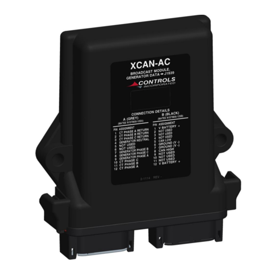
Generator Control Installation Kits Installation kits are available which include the following 1) Control panel, P/N G3-2500 2) Generator monitor, P/N XCAN-AC 3) Current transformers, size and quantity depend on installation 4) Generator wiring harnesses, P/N 70-0670-5 (5 Foot) 5) Intermediate Harness, P/N 70-0671-5 (5 Foot) - Page 4 S O L U T I O N S Connections The XCAN-AC module has two twelve-pin sockets that are keyed and color-coded to make identification easy and prevent miswiring. The right socket (black) is the DC side connection and the left socket (gray) is the AC side connection.
- Page 5 Phase A Required Phase A Voltage and CT inputs must be connected in order for the XCAN-AC to determine frequency and phase angle. In the event of Phase A loss in a three-phase wye connection, the voltages and currents on the other two phases will still be reported, but the frequency will be reported as zero, and the KVar and KW readings will be based on a power factor of 1.0.
- Page 6 CONTROLS, INCORPORATED C O N T R O L S Y S T E M S & S O L U T I O N S Wiring Diagram – Wye - 5 -...
- Page 7 CONTROLS, INCORPORATED C O N T R O L S Y S T E M S & S O L U T I O N S Wiring Diagram – Delta Must be specified at time of order or configured through CI Station...
-
Page 8: Module Setup
S O L U T I O N S MODULE SETUP The XCAN-AC can be configured by two methods, by configuring a bank of dip switches on the PCB or by using the CI Station, pc-based programming software. DIP SWITCH CONFIGURATION 1. - Page 9 S O L U T I O N S CI STATION CONFIGURATION The XCAN-AC Can be configured using the CI Station, pc-based programming software. Current transformer size, AC configuration, primary and secondary CAN Source Addresses can be selected and saved for future use.
- Page 10 CONTROLS, INCORPORATED C O N T R O L S Y S T E M S & S O L U T I O N S 5. To change the AC winding configuration, use the drop-down box labeled Phasing. Select the correct configuration for your application.
- Page 11 Each end of the CAN Bus should contain a 120- ohm terminating resistor. The pcb in the XCAN-AC has a 120-ohm resistor that can be included into the CAN High and CAN Low lines by using a pcb jumper. The jumper is labeled JP1 on is identified in the picture below.
- Page 12 CONTROLS, INCORPORATED C O N T R O L S Y S T E M S & S O L U T I O N S J1939 Broadcast Data Below is a table of the broadcast information. Information is available without requesting.
- Page 13 CONTROLS, INCORPORATED C O N T R O L S Y S T E M S & S O L U T I O N S CAN Trace - 12 -...
- Page 14 S O L U T I O N S 10) Warranty CONTROLS, INC. is herein called “Seller”. The person, firm or corporation to whom or which the sale is made is herein called “Buyer”. Seller warrants to the Buyer that all products furnished under this order will conform to Seller’s specification, drawings as described in its...
Need help?
Do you have a question about the XCAN-AC and is the answer not in the manual?
Questions and answers