Table of Contents
Advertisement
Advertisement
Table of Contents

Related Manuals for Controls CX Series


Summary of Contents for Controls CX Series
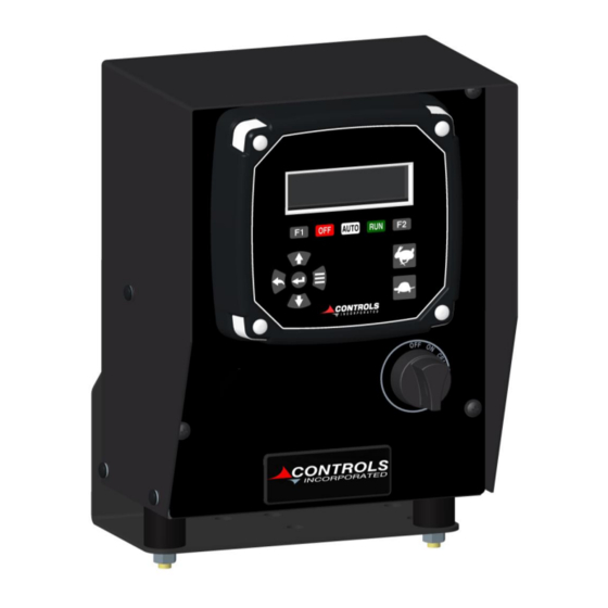
- Page 1 PRODUCT MANUAL ENGINE CONTROL MODULE CX SERIES Part Number: CX-7500-AS Revision: V1.1 Engine Type: Electronic and Mechanical Engines ______________________________________________________________________________________________________________________________________...
-
Page 2: Table Of Contents
TABLE OF CONTENTS INSTALLATION …….…………………………………………………………………………………….…………………………………………..…………. CONSIDERATIONS DIMENSIONAL WIRING SCHEMATIC MANUAL OPERATION ……………………………………………………………………………………..…………..……………………………… POWER UP MANUAL OFF MANUAL STARTING SAFETY BYPASS ENGINE RUNNING SPEED CONTROL ELECTRONIC SPEED CONTROL MECHANICAL STOPPING THE ENGINE AUTO START FLOAT OPERATION ………………………………………………………………………….………….……………………. SINGLE FLOAT DUAL FLOAT DRAIN OR FILL MODE AUTO START USING TRANSDUCERS. - Page 3 SPEED CONTROL OPTIONS …………………………………………………………………………………………………………………………. ELECTRONIC ENGINE SPEED CONTROL REQUESTED VERSUS ACTUAL SPEED TSC VERNIER THROTTLE TSC BUMP TSC MULTISTATE THROTTLE TSC HI-LO MOMENTARY THROTTLE FLEX ANALOG THROTTLE MODBUS THROTTLE SPEED / TORQUE LIMIT COOPERATIVE THROTTLE TWIST THROTTLE KNOB DISPLAY CONFIGURATION ……………………………………………………………………………………………………………………….
- Page 4 MAIN MENU TOPICS ……...………………………………………………...…………………………………………….……..….………………. ACTIVE ENGINE FAULT CODES SERVICE FAULT CODES STORED ENGINE FAULT CODES ENGINE PARAMETERS EMISSION PARAMETERS SENDER PARAMETERS PUMP PARAMETERS OPERATION EVENT LOG ALARM EVENT LOG ENGINE IDENTIFICATION MODULE INFORMATION CONTROLLER SETUP MODULE PROGRAMMING ……...………………………………………………...……………………………………………….………………. PROGRAMMING OPTIONS PC BASED PROGRAMMING MODULE BASED PROGRAMMING CONTROLLER SETUP MENU..
- Page 5 AUTO OPERATION SETTINGS AUTO START CONFIGURATION BATTERY RECHARGE CONFIGURATION MAINTENANCE CONFIGURATION EMISSIONS CONFIGURATION MODBUS CONFIGURATION CLUTCH CONFIGURATION CLOCK SET UP DIAGNOSTICS INFORMATION PANEL CONNECTORS ………………………………………………………………………………..……………………………………………... DAISPLAY CONNECTORS ………………………………………………………………………………..……………………….……………... WARRANTY ………………………………………….……………………………………………………………………….……………………….……..
-
Page 6: Installation
ENCLOSURE MOUNT: If your installation is better suited for a full control panel rather than a module, contact Controls, Inc. for available options or assistance in selecting an enclosure for your application. - Page 8 CUSTOMER CONNECTION DIAGRAM...
- Page 9 INTERNAL PANEL WIRING DIAGRAM...
-
Page 10: Manual Operation
SPECIAL NOTE When using the CX-7500-AS as a replacement panel, check the Regen Switch Address to make sure the engine can regen properly MANUAL OPERATION POWER UP Turn on the power to the display using the ON/OFF/CRANK key switch. The display will illuminate and show the module part number version in the upper left status line and the graphical logo will be centered in the screen. -
Page 11: Manual Off
CONTROLLER MODES Note: All text written in bold, underlined, italics are status message shown in the upper left of the display. MANUAL OFF After the Power Up cycle is complete, the module will be in the Manual Off mode as shown in the upper left status line and the corresponding red LED indicator above the OFF button. -
Page 12: Manual Starting
MANUAL STARTING Starting the engine manually cab be done is two ways. You can use the key switch and rotate it clockwise to the spring loaded CRANK position, or with the key in the ON position, you can press the green RUN button. -
Page 13: Safety Bypass
SAFETY BYPASS Immediately after the engine begins to run, the module will enter the “Safety Bypass” period. This time period is typically set to 10 seconds and is programmable. During this period, any engine parameter set to be monitored as RUN will be ignored until the bypass period is passed, at which point the safeties will become active. -
Page 14: Speed Control Electronic
SPEED CONTROL - ELECTRONIC ENGINES The display can control the engine’s speed using J1939 Torque Speed Control (TSC1). When the engine is started manually, the control panel will request the minimum programmed speed. Pressing the Up-arrow button will cause the panel to increase the requested speed. The display will place an up or down arrow to the right of the RPM displayed to indicate that a change in speed is being requested. -
Page 15: Stopping The Engine
STOPPING THE ENGINE When it comes time to stop the engine, you may want to slow the engine down to a low idle speed and allow to run for a period of time to assist in turbo cooling if equipped. Then, simply press the red OFF button or turn the key to the OFF position. -
Page 16: Auto Start Float Operation
AUTO START FLOAT OPERATION SINGLE FLOAT SYSTEM Basic level control can be accomplished using a float device that contains a contact closure internally. For applications that do not have critical start and stop points and do not involve turbulence, such as a pond or lagoon, a single float can provide adequate control over water levels. -
Page 17: Drain Or Fill Mode
DRAIN OR FILL MODE The panel can easily be configured for either draining or filling a sump using the float system. Under the Quick Setup menu, you can select either the Drain or Fill mode. Once selected, the Pump Display will update with the words Fill or Draining and place the ON and OFF in the proper locations for reference. -
Page 18: Auto Start Using Transducers
AUTO START USING TRANSDUCERS LEVEL CONTROL A level transducer can be used to provide automatic starting and stopping of the pump based on programmable levels. The panel is defaulted to use a 4-20mA, 0-10 psig (0”-277”) transducer, and provides an M12 connector located on the rear of the enclosure which is labeled. Under the Pump Quick Setup, you set your Start/Stop Input to Transducer and follow the menu where you can select the desired starting and stopping levels. - Page 19 The Inlet transducer is defaults to a 30 “Hg to 30 psi and the outlet transducer defaults to a 0-300 psi. Both are 4-20mA devices. A general system pressure can be used as well in lieu of either the Inlet or Outlet options.
- Page 20 AUTO START INFORMATION GENERAL INFORMATION The CX Series displays have a high degree of configurability when it comes to auto start applications. The information herein is designed to be a general guide to the different methods of auto start operation. An auto start signal can come from a digital input(s), Modbus, CANbus or from the real- time clock scheduler.
- Page 21 AUTO START MODE With power on to the module, press the white AUTO button to place the unit in the Auto Start mode. The display will indicate that the module is now in the Auto mode. The status line will display Auto Off. While in the Auto Off mode, the controller will await an auto start signal.
- Page 22 SCHEDULER AUTO START If the Scheduler is set up to provide starting and stopping based on the time of day and day of week, the status/mode line will rotate to show the next start event. Once running under the scheduler, the Stop time will be displayed.
- Page 23 AUTOMATIC SINGLE SPEED CONTROL MODE When operating in Auto, the controller will start the engine at the warm up speed and maintain that speed until the warm up time delay expires. After that, the control will ramp the speed up to the Prime Speed setting and maintain that through the time period.
-
Page 24: Speed Control Options
SPEED CONTROL OPTIONS ELECTRONIC ENGINE SPEED CONTROL The display can control the engine’s speed using J1939 Torque Speed Control (TSC1). When the engine is started manually, the control panel will request the minimum programmed speed. Pressing the Up-arrow button will cause the panel to increase the requested speed. The display will place an up or down arrow to the right of the RPM displayed to indicate that a change in speed is being requested. -
Page 25: Requested Versus Actual Speed
The control panels TSC address and the engine’s ECU address must match. Most major engine manufacturer’s TSC addresses are loaded into the control panel when that engine manufacturer is selected in the Quick Setup. However, there may be instances where ECU programming may vary. The control does have the ability to change the TSC address manually in the CAN Configuration menu. -
Page 26: Tsc Vernier Throttle
TSC VERNIER THROTTLE TSC Vernier is the most popular throttle selection when operating in the manual start mode. The operator can control the engine speed anywhere between the programmed speed range. This throttle type allows you to set the minimum engine speed, maximum engine speed, ramp rate, curve type and bump speed increments without the use of a computer. -
Page 27: Tsc Multistate Throttle
TSC MULTISTATE THROTTLE Another widely used throttle type in manual mode allows the operator to increment the engine speed between predetermined speed settings by pressing the Rabbit or Turtle buttons. The number of discreet speeds set is up to four ascending speeds. After the operator starts the engine, the controller will run the engine at Speed 1 setting, the lowest speed. -
Page 28: Flex Analog Throttle
MODBUS THROTTLE Engine speed can be requested through the modules RS485 MODBUS interface. Contact Controls, Inc. for a complete register map. The example for speed control is below. Use of 40004 or 40051 is acceptable. -
Page 29: Cooperative Throttle
The main module must be configured as the Primary, while the remaining modules should be set to remote. TWIST THROTTLE KNOB The TT-100 throttle knob is available to work with Controls, Inc. modules as well. Contact CI for more details. -
Page 30: Graphical Display
DISPLAY CONFIGURATION GRAPHICAL DISPLAY The CX Series uses a 3.2” diagonally measured, OLED (Organic Light Emitting Diode) display with a resolution of 256x64 pixels. The OLED technology provides a vibrant display that is highly readable in direct sunlight while also offering a wide temperature range of -40C to +80C for both operating and storage. -
Page 31: Factory Display Configuration
FACTORY DISPLAY CONFIGURATION The CX-7500-AS display is set up to show the three screen below. The information shown can be customized for individual applications if desired using the front panel menu system or CI Station PC application. DISPLAY A DISPLAY B DISPLAY C... -
Page 32: Display Customization
DISPLAY CUSTOMIZATION There are three objects that can be used to create your display. Digital, Analog and Custom structures are available to tailor the screen to display what is important to your piece of equipment. Customization is available in Areas 1 through 8. Digital –... -
Page 33: Protection Options
PROTECTION OPTIONS ECU SAFETY SHUTDOWNS AND WARNINGS Once the engine is started, the engine’s ECU has primary control over the operation of the engine under safe conditions. If the ECU detects that any of its critical parameters are out of tolerance, the ECU can take a variety of actions, including derating of the engine horsepower or complete engine shut down. -
Page 34: Module Safety Shutdowns And Warnings
MODULE SAFETY SHUTDOWNS AND WARNINGS The control panel also has the ability to monitor the engine vitals if configured. The ability to set pre alarms and alarms in the panel is supported to back up the ECUs safeties in the event the ECU shutdowns were not enabled or a more conservative setting is desired. -
Page 35: Low Power Sleep Mode
LOW POWER (SLEEP) MODE A low power mode is available to allow the module to minimize power consumption during times when the panel is on, but the engine is not running. Options include auto start mode or manual start mode, when the engine did not start, or a shutdown condition. To minimize current draw, the module goes into a sleep mode after a programmable time period (two-minute default) after being powered on without the engine starting or after a protection shutdown occurs. -
Page 36: Other Module Functionality
OTHER MODULE FUNCTIONALITY STANDARD FEATURES The control panel has many options that can be configured, enabled or selected that will enhance the operation of the equipment. A list of items is below with descriptions on the selection and use of each. -
Page 37: Audible Horn
AUDIBLE HORN An alarm horn can be driven from an output to annunciate alarm conditions and/or a pre-start warning on auto start applications. When an output is assigned to any Horn function, the Enter button will be used the silence the horn. -
Page 38: Shutdown Override
SHUTDOWN OVERRIDE The module contains logic that can be enabled to provide a safety shutdown override. The override applies to any module monitored and activated alarm. It does not apply to engine ECU safety shutdowns. For ECU overrides, consult with your engine supplier. To use this feature, an available digital input must be assigned to the Shutdown Override action and have a switch connected to it. -
Page 39: Main Menu Access
MAIN MENU ACCESS To access the module menu system, apply power to the module and press the Menu button. ENTER BACK MENU DOWN If the engine is running, the throttle buttons will remain active for speed control. The menu system is broken into two main sections;... - Page 40 engine type and control panel model. Pressing the Up and Down button will move the highlighted selection up or down in the list. Indicator Arrows show if there are additional subjects above or below the current screen view. Pressing the Enter button will select the highlighted sub menu. Menu Topic Sub Menus...
- Page 41 MAIN MENU TOPICS The Main Menu contains many areas that are useful for the routine operation and troubleshooting of an industrial engine. Each feature cannot be covered in this manual; however, a list of main topics is below. ACTIVE ENGINE FAULT CODES If the engine’s ECU is generating trouble codes, they can be viewed from this menu.
- Page 42 ENGINE PARAMETERS Engine’s ECUs collect a large amount of information about the operating conditions of the engine. To view more of these details and gain a better understanding of your engine’s operating conditions, view this menu. EMISSIONS PARAMETERS For engines equipped with emission components, a menu is available to view these details.
- Page 43 PUMP PARAMETERS If the four analog senders are configured for pump use, the values can be seen here. Note, you must select either Application Level or Application Pressure when configuring the transducers. OPERATION EVENT LOG The module will record the last 32 operational events and show the most recent first. The event log can be cleared in the Module Configuration menu of the Controller Setup area.
- Page 44 ENGINE IDENTIFICATION Use this menu to view the engine’s Model and Serial number. MODULE INFORMATION Use this menu to view the detailed information about your MX Series module.
- Page 45 The CI Station allows the user to save configurations and reuse them over and over for production line programming or to configure replacement panels to match the original OEM programming. Contact Controls, Inc. for more details.
- Page 46 MODULE BASED PROGRAMMING The control panel will come with a factory configuration unless otherwise specified. Consult with your sales channel for modifications to the factory configurations. A Quick Setup menu is located under the Controller Setup area that will provide the basic selections you may want to review and/or change to meet your needs.
- Page 47 CONTROLLER SETUP When navigating through the Main Menu you will arrive at the Controller Setup selection. To configure the module to new settings, you can enter into this area by pressing the Enter Button PASSWORD ENTRY The next screen will ask for a password. If no password, or an incorrect password is used, navigation into the menu is still possible and permitted, however, the ability to make changes will be restricted.
- Page 48 SETUP MENU Navigating the Controller Setup menu structure is done in the same manner as the Main Menu system. Up and Down arrows will scroll to the next topic; Enter button will access the topic, etc. To make changes to the settings, you will need to locate the item you are looking to modify under the appropriate topic and then press the Enter button.
- Page 49 QUICK SETUP This menu is designed to allow you to configure the module in a simple manner, asking you to select the most common options used with today’s industrial engines. Based on your selections here, other items will be affected. For example, if you select Engine Type as Mechanical, the module will default the engine oil pressure, coolant temperature and speed sender options to be typical senders rather than J1939.
- Page 50 PUMP PARAMETER CONFIGURATION Individual pump parameters can be changed here. Two transducers can be configured for Inlet and Discharge pressures. Note: These two inputs are also associate with analog oil pressure and coolant temp. They must be assigned to one or the other, not both. SCHEDULER CONFIGURATION The module can be set to start and stop the engine based on the time of day and day of the week.
- Page 51 INPUT CONFIGURATION The module has two on board digital inputs that can be configured in a large variety of ways. All digital inputs are pulled high and must be closed to ground. Additional REMOTE I/O can be configured when used with an XCAN-IO-664 from simple switch shutdowns to remote engine operation, contact CI application engineers to discuss.
- Page 52 THROTTLE CONFIGURATION The speed control behavior of the engine can be changed under the Throttle Configuration menu. Selection of throttle type, minimum operating and maximum operating speeds and other details as well can be set here. See Speed Control Options for more details. ENGINE SAFETY CONFIGURATION The module can provide warnings, shutdowns, deceleration, and other behaviors based for the critical engine parameters of oil pressure, coolant temperature, engine speed, fuel level and battery voltage.
- Page 53 PUMP SAFETY CONFIGURATION The module can provide warnings, shutdowns, deceleration, and other behaviors for the critical pump parameters of suction pressure and discharge pressure. Simply set the thresholds and actions desired. In the example below, a warning will be annunciated if the discharge pressure rises above 200 psi and the engine will be decelerated to minimum speed if it exceeds 250 psi.
- Page 54 DISPLAY CONFIGURATION Use this area to set up the display with the parameters you desire to see on the full-time display. For details on configuration, see DISPLAY OPTIONS in this manual. In the example below, Area 3 would display engine Oil Pressure in digital format. The AG suffix stands for Analog Gauge presentation. CAN CONFIGURATION This menu is used to define how and what messages are transmitted on the J1939 CAN Bus.
- Page 55 AUTO START CONFIGURATION These settings define the time delays and speeds that will be used during an auto start routine. Warm Up Seed, Prime Speed, Cooldown Speeds are programmed here. BATTERY RECHARGE CONFIGURATION The module can be used to monitor the engine starting battery voltage and start the engine if the voltage drops below a programmed setting.
- Page 56 MAINTENANCE CONFIGURATION If you would like to set up service intervals for your equipment, use this menu to establish up to three unique service schedules. You can set the time between, name of service, and when to being warning of impending service requirements. EMISSION CONFIGURATION If your engine is equipped with emission components, you may use this menu to setup additional warnings, enable and disable regen options and other CAN based messaging.
- Page 57 MODBUS CONFIGURATION (OPTIONAL) When connecting to a MODBUS devise such as PLCs, telematics or other controls, this menu will define the communication protocol for successful integration. The modules are designed to operate as a MODBUS RTU. CLUTCH CONFIGURATION Two channels of interlocking output behavior can be configured using outputs 5-8 in the module.
- Page 58 CLOCK SETUP When you receive your module, it should be programmed with the correct date and time for the Eastern US Time zone. The real-time clock on the module is backed up by a large capacitor that will keep the time correct for 2 to 3 months while it sits in the box. If reprogramming is needed, you can access this menu or use the CI Station setup too.
- Page 59 PANEL CONNECTORS FLOAT CONNECTOR CPC (796095-2) LEVEL TRANSDUCER M12 (FKFDW4505) FLOW METER M12 (FKFDW4505) ACCESSORY HARNESS ENGINE HARNESS HDP24-24-31PE HDP24-24-21PE FLOAT CONNECTOR Function High Float Input Low Float Input Low Float Return High Float Return...
- Page 60 LEVEL TRANSDUCER FLOW METER Function Function Transducer Signal Transducer Signal Transducer B+ Supply Transducer B+ Supply ENGINE HARNESS ACCESSORY HARNESS Function Function Power to ECU / Fuel Solenoid Relay 5 Output (5 Amp) Alternator Excite (D+) Suction Transducer Signal Battery Positive (B+) Digital Input 8 Preheat Signal Digital Input 9...
- Page 61 MODULE PRIMARY CONNECTOR Ampseal 776273-1 Mating Plug with 770854-3 Sockets Function Function ECU Power / Fuel Solenoid J1939 Low Horn Signal Common B Positive Crank Signal Manual Crank Detect Battery Positive Battery Positive Crank Signal Battery Negative Common B Positive Fuel Level Sender J1939 High High Float Input...
- Page 62 WARRANTY CONTROLS, INC. is herein called “Seller”. The person, firm or corporation to whom or which the sale is made is herein called “Buyer”. Seller warrants to the Buyer that all products furnished under this order will conform to Seller’s specification, drawings as described in its current catalog or quotation and will be free from defects in materials and workmanship.
Need help?
Do you have a question about the CX Series and is the answer not in the manual?
Questions and answers