Table of Contents
Advertisement
Quick Links
Advertisement
Table of Contents

Related Manuals for Promax ATLAS NG


Summary of Contents for Promax ATLAS NG
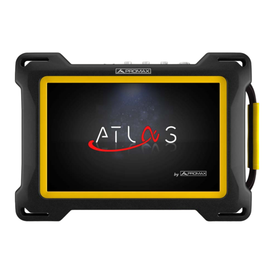
- Page 1 ATLAS UNIVERSAL BROADCAST ANALYZER -0 MI2130 -...
- Page 2 SAFETY NOTES Read the user’s manual before using the equipment, mainly "SAFETY RULES" paragraph. The symbol on the equipment means "SEE USER’S MANUAL". In this manual may also appear as a Caution or Warning symbol. WARNING AND CAUTION statements may appear in this manual to avoid injury hazard or damage to this product or other property.
- Page 3 SAFETY RULES * The safety could not be assured if the instructions for use are not closely followed. * Use this equipment connected only to systems with their negative of measurement connected to ground potential. * The AL-103 external DC charger is a Class I equipment, for safety reasons plug it to a supply line with the corresponding ground terminal.
- Page 4 SAFETY SYMBOLS DESCRIPTIVE EXAMPLES OF OVER-VOLTAGE CATEGORIES * Cat I: Low voltage installations isolated from the mains. * Cat II: Portable domestic installations. * Cat III: Fixed domestic installations. * Cat IV: Industrial installations. CAUTION: The battery used can present danger of fire or chemical burn if it is severely mistreat.
-
Page 5: Table Of Contents
4.4.11.Transport Stream Analyzer ..................38 4.4.12.Transport Stream Tables ..................38 4.4.13.Transport Stream Bitrate ..................39 4.4.14.Transport Stream PIDs ....................41 4.4.15.Transport Stream Alarms ..................42 5. SPECIFICATIONS ATLAS NG ..............44 5.1. General....................44 5.2. TV Analyzer Mode..................48 5.2.1.Supported Standards ....................48 5.2.2.TV Analyzer Tools .....................53 5.3. Spectrum Analyzer Mode ................54... - Page 6 5.6. SDI Mode .....................56 5.5. ASI Mode .....................56 5.7. Options ....................57 6. MAINTENANCE ..................58 6.1. Instructions for Returning by Mail ............58 6.2. Considerations about the Screen .............58 6.3. Cleaning Recommendations ..............58 7. ADDITIONAL INFORMATION ..............60 8. MULTIMEDIA CONTENT ................61 9.
-
Page 7: Introduction
The new ATLAS NG has been created with the aim to make easy the user experience. Everything has been designed so the equipment can be fully operated using the 10”... - Page 8 The ATLAS NG has a variety of input-output connectors that allows it to work with most of the broadcast signals: N-type universal, 1PPS, FC/APC, ASI-SDI, SFP+, HDMI, Ethernet among others. It can be connected to a network and be remotely managed very easily using a standard browser.
-
Page 9: Setting Up
Power The ATLAS NG is powered by a 7.4 V built-in rechargeable Li-Po battery of high quality and long operation time. This equipment can operate on battery or connected to the mains using a DC adapter. An adapter is also supplied to use with the power connector car (cigarette lighter). -
Page 10: Charging The Battery
2.2.1 First Charge The equipment comes with the battery half charged. Depending on the time elapsed from first charge and environmental conditions may have lost some of the charge. You should check the battery level. It is advisable a first full charge. 2.2.2 Charging the Battery Connect the DC power adapter to the equipment through the power connector... -
Page 11: Charge / Discharge Times
2.2.3 Charge / Discharge Times Average charging time with the equipment off (fast charge): 3 hours to achieve an 80% charge. 5 hours to achieve a 100% charge. With the equipment on (slow charge): 5 hours to achieve an 80% charge. 8 hours to achieve a 100% charge. -
Page 12: Usage Tips
Usage Tips The battery is losing storage capacity as you go through its life. Contact your PROMAX distributor when necessary to replace the battery. To extend battery life the user should follow these tips: In case of providing a long inactivity period of the equipment it is advisable to make every 3 months a charge / discharge cycle and a subsequent partial charge (40% aprox.). -
Page 13: Equipment Details
Equipment Details Inputs and Outputs (03:13s) Figure 3. Front View. February 2023 Chapter 2: SETTING UP... - Page 14 Figure 4. Left Side View. HDMI output for HDMI 1.4 (UHD 4K). USB Host/Device connector (selectable). RJ45 connection for remote management. Analogue Video/Audio input/output. Power input connector. LED indicator for battery charge level. Chapter 2: SETTING UP February 2023...
- Page 15 Figure 5. Top View. ON/OFF. Press for an instant to switch on/off. USB 3.0 port for WiFi dongle, GPS receivers or USB drives. RJ45 connector for IPTV or OTT signal analysis. SFP+ transceiver compatible with GE and fiber optics. ASI/SDI output signal. ASI/SDI input signal.
-
Page 16: Reset
Switching On/Off Switching On: ► Press the ON/OFF button placed on the top of the equipment for few seconds. The boot screen appears and also a progress bar that indicates the system is loading. After the system loads, it shows the same status before power off. Switching Off by button: ►... -
Page 17: Icons
When to RESET: When it crashes and does not respond to any key. When it does not switch on. When it does not finish the boot process. Icons Icons on screen provide useful information about the equipoment: Icon Description Icon Description Attenuator: The input signal has an Signal Quality according to threshold: Correct... -
Page 18: Home Menu
Home Menu To access the Home Menu from any screen press the PROMAX logo at the left bottom corner. From the Main Menu you can access the main tools as described below. Main Menu (05:23s) TV Analyzer: Tool to analyze and demodulate terrestrial, CATV or... -
Page 19: Rf Terrestrial Signal Tuning
Practical examples The next section is a general explanation of how to tune a terrestrial or a satellite RF signal, step by step. If you have any doubt, check the specific chapter to get more details. 2.8.1 RF Terrestrial signal tuning Connect the RF input signal cable to the RF input connector. - Page 20 Press Settings Press StealthID and select the type of signals you want to identify automatically when it is searching a signal (in this case should be satellite signals as DVB-S, DVB-S2, etc.). Press to return to the Home menu. From the Home Menu press on the TV Analyzer On the main panel, press and select the Spectrum tool on the main panel.
-
Page 21: Settings And Preferences
3 SETTINGS AND PREFERENCES Settings Menu Press Settings on the Home Menu to access the Settings menu. Settings Menu (02:19s) Settings are classified according to these categories: General: Equipment information and customizing options. TV Analyzer: TV analyzer settings. IPTV: IPTV settings. Spectrum Analyzer: Spectrum analyzer settings. - Page 22 Appearance ► Power Off: It allows the user to select the time to power off, which is the time after which the equipment shuts down automatically unless an user press any key. Language: Language used on menus, messages and screens. Available languages are: English, Spanish and Catalan.
-
Page 23: Tv Analyzer Settings
DNS1 DNS2 Software Update ► Last Update Information: It shows information about the current update. Update: It shows if there is an update available for download and install. 3.1.2 TV Analyzer Settings Measurements ► Terrestrial Units: It allows the user to select the terrestrial measurement units for the signal level. -
Page 24: Iptv Settings
Stealth-ID Options ► It allows the user to select the set of signal types being used while auto identifying any modulation type. •Annex B. •FM •DVB-C •DVB-T •DVB-T2 •ISDB-T •ATSC •ATSC-3 •DAB •DVB-S •DVB-S2 •DVB-S2X •DSS 3.1.3 IPTV Settings Network ►... -
Page 25: Interface Menu
streams. IGMPv3 ► IGMP Versions: Protocol for multicast transmissions used by the router. •IMGPv1: IGMP version 1. Each time user selects a multicast address, meter asks for the new multicast stream. •IMGPv2: IGMP version 2. Each time user selects a multicast address, meter stops receiving the current stream and asks for receiving the new one. - Page 26 HDMI: It shows info about the HDMI input. Chapter 3: SETTINGS AND PREFERENCES February 2023...
-
Page 27: Tv Analyzer
4 TV ANALYZER Introduction The TV Analyzer mode allows you to analyze RF signals: terrestrial, satellite, CATV or FM. It can demodulate and display services for terrestrial/CATV from 45 to 1000 MHz and satellite from 250 to 2350 MHz. TV Analyzer Basics (02:58s) The TV Analyzer screen is divided into 3 panels: the main panel the top small panel... -
Page 28: Tv Analyzer Screen
TV Analyzer Screen Figure 6. Triangle (all panels): It displays a menu with all available tools. Select one tool to be displayed on the panel. The same tool cannot be in more than one panel (for more details about tools refer to “Tools”... -
Page 29: Tuning Settings
Info Bar: It is the bar at the top of the screen. From left to right shows: Type of tuned signal (terrestrial/Satellite); name of selected workspace; attenuation enabled/disabled; supply output enabled/disabled; time; battery. Tuning Settings To display the Tuning Settings swipe right from the left side of the screen or press any field related to tuning (frequency, span...) Band: It allows selecting between terrestrial or satellite frequency band. -
Page 30: Tools
The attenuator must be adapted to the installation according to the RF power (modulation index). Tools In the next sections each tool for the TV Analyzer is explained. They are: Spectrum Measurement Video Video Values Signal Parameters Constellation MER by Carrier Recording FM RDS Parameters FM Histogram... - Page 31 Vertical drag: It changes reference level. Screen ► Figure 7. Spectrum: The red vertical line shows the frequency been tuned. At either side there are two dotted white lines that define the signal bandwidth over which the meter is trying to identify the tuned signal. When the signal is tuned, the meter auto identifies it.
-
Page 32: Measurement
yellow background. Gradient shows the spectrum with a gradient of yellow background. Marker: It defines how to display the marker: Line, marker or horizontal. Resolution filter: It defines the resolution bandwidth filter value. Resolution filters available are: 2 kHz (only terrestrial band), 10 kHz, 20 kHz, 30 kHz, 40 kHz, 100 kHz, 200 kHz and 1000 kHz. - Page 33 Screen ► Figure 8. Monitoring graph: It shows the selected measurement being plotted on a graph over time. The user can select any of the measurements available on the panel below. The selected measurement is inside a yellow frame. .Relevant Measurements: It shows the most relevant measurements for the tuned signal.
-
Page 34: Signal Parameters
4.4.3 Signal Parameters The signal parameters tool displays the modulation parameters of the signal being tuned and demodulated. Signal Parameters (00:32s) Screen ► Figure 9. General Panel: It displays the most relevant information. .Specific panel: It shows detailed data. Chapter 4: TV ANALYZER February 2023... -
Page 35: Video
4.4.4 Video The video tool displays one of the services carried by the signal being demodulated. Video (01:15s) Screen ► Figure 10. Video Panel: It displays the demodulated service. .Service bar: It shows the name of the service and quality. If pressing, it opens a new window that shows all services available for the transport stream. -
Page 36: Recording
Settings ► Press on the gear to display settings: Audio: It allows the user to change language of the service in case there is more than one available. 4.4.5 Recording The recording tool allows recording the full transport stream from the demodulated signal being tuned. -
Page 37: Constellation
File information Panel: On the left you can see start time, duration and file size. On the right side there is the total memory and free memory available. .On/Off button: It shows a red button to start/stop recording. If pressing when the button is a cercle it starts recording and when it is square it stops recording. - Page 38 Screen ► Figure 12. General Panel: It displays the signal demodulated. The constellation is a pattern that shows the symbols received by the demodulator. Symbols are colour coded according to the density of points falling the same area across time. The greater amount of impacts in an area, the warmer the colour of symbols.
-
Page 39: Video Values
4.4.7 Video Values It shows details about the service selected and its video and audio layers. Video Values (01:43s) Screen ► Figure 13. General Panel: It provides service information: name, provider and network name. Also Service ID, Logical Channel Number, transport stream ID, Network ID, original network ID, if the service is scrambled, audio language, subtitles language and some others. -
Page 40: Mer By Carrier
If you amplify this tool to full screen pressing on Plus it shows a new area on the left side with more details about the service layers and also about the MPD file if there is any. 4.4.8 MER by Carrier The MER by carrier tool measures the MER for each carrier in the channel and shows it graphically. -
Page 41: Echoes
.Measurement panel: It shows the average MER for all carriers and its standard deviation. If there is an interference signal, a drop in the MER of the affected carriers will occur. The fields Carrier and MER shows these values for a single carrier selected by the user. -
Page 42: Fm Rds Parameters
Screen ► Figure 15. Graph Panel: It shows the echoes. The horizontal axis shows time (us) and the vertical axis shows level (dB carriers). It can display up to 10 echoes. Everything falling in between the red areas is received within the guard interval, everything falling in the read areas are outside the guard interval and therefore very damaging. - Page 43 Screen ► Figure 16. General Panel: The column on the left shows several RDS data fields. The column on the right shows alternative frequencies. .Specific panel: The column on the left shows different operation modes of the decoder. The column on the right shows extra text information. RDS Data ►...
-
Page 44: Transport Stream Analyzer
Local: Local time. 4.4.11 Transport Stream Analyzer The Transport Stream (TS) Analyzer is a set of tools that provides the user with a comprehensive analysis of the transport stream extracted from the digital signal being tuned. The transport stream can be received through any of the equipment inputs. -
Page 45: Transport Stream Bitrate
Screen ► Figure 17. General Panel: It shows all metadata extracted from the transport stream. These are the PSI (Program Specific Information) and SI (Service Information) tables and all their related fields. They can be unfolded to see its subfields. 4.4.13 Transport Stream Bitrate The TS bitrate tool shows the nominal bitrate for each service within the TS in... - Page 46 Screen ► Figure 18. Services panel: It shows all services in the transport stream in real time. The “Others” service indicates the amount of bitrate used by the PSI/SI tables. The pie chart indicates the percentage contribution in bitrate per service in respect to the total TS bitrate, including null packets, which are displayed in black.
-
Page 47: Transport Stream Pids
4.4.14 Transport Stream PIDs The TS PIDs tool lists all the PIDs in the Transport Stream. Video Screen ► Figure 19. PID Panel: It displays all the PIDs in the analyzed TS. For each PID describes its content and their minimum, average and maximum bitrates. Touch gestures ►... -
Page 48: Transport Stream Alarms
Order by: It allows ordering by PID, bitrate, max. bitrate, min. bitrate or description. Reset: It resets and captures the PID list. 4.4.15 Transport Stream Alarms The TS Alarms tool shows the list of alarms which are classified in three priority levels (according to TR 101 290 guidelines by DVB group). - Page 49 Touch gestures ► Tap: It opens an alarm to show log, description and settings menu. Settings ► Press on the gear to display settings: Reset: It initiates the alarm analysis from scratch. Restart: It initiates the capture of PSI/SI table info again followed by the alarm analysis.
-
Page 50: Specifications Atlas Ng
Input Connector Multipole Jack Zin=10k; same V/A input multipole jack Digital Video / Audio Output Output Connector HDMI 1.4 specification 3840x2160 @30 Hz Resolution Audio Output Output Connector Multipol Jack 32 Ω Stereo Chapter 5: SPECIFICATIONS ATLAS NG February 2023... - Page 51 IP by default Connector DVB-CI compliant CAM module input WiFi Interface Type Wireless standard 802.11 abgn Dongle-Wifi connected to USB port Dongle must be validated by PROMAX Remote control Interfaces Interfaces RJ45 Ethernet; USB Virtual COM; WiFi Remote control JSON: sending and receiving remote...
- Page 52 3.4 kg Without installed options Volume 5,5 cm ►Power Supply Parameter Value Additional Data Internal Battery 7.4 V; 18.3 Ah Li-Po Smart battery Battery Operation Time > 4 hours With smart power management Chapter 5: SPECIFICATIONS ATLAS NG February 2023...
- Page 53 1x DC-230 Transport suitcase 1x DG0399 Quick Reference Guide 1x MN-001 Monopod NOTE: It is recommended to keep all the packing material in order to return the equipment, if necessary, to the Technical Service. February 2023 Chapter 5: SPECIFICATIONS ATLAS NG...
-
Page 54: Tv Analyzer Mode
NorDig-Unified Test Specs ver2.5.0 portable equipment and targeting DTG D-Book 8.0 upcoming Digital Europe e-book requirements Carriers Guard Interval Bandwidth Spectral Inversion Pilot Pattern PLP Code Rate PLP Constellation PLP Constellation Rotation PLP ID Chapter 5: SPECIFICATIONS ATLAS NG February 2023... - Page 55 45 - 115 dBμV Measurements Power, CBER, MER, PER, C/N, LBER, BCH ESR, LDP Iterations Tuning Range 45 - 1000 MHz Standard compliant Digital Video Broadcating for cable ETSI EN 300-429 v1.2.1 systems Carriers February 2023 Chapter 5: SPECIFICATIONS ATLAS NG...
- Page 56 45 dBμV - 115 dBμV Measurement Power, CBER, MER, PER, C/, LBER, BCH ESR, LDP Iterations Tuning Range 45 - 1000 MHz Standard compliant ATSC Digital Television Standard ATSC A/321 (2016) ATSC A/322 (2017) ATSC A/330 (2016) Chapter 5: SPECIFICATIONS ATLAS NG February 2023...
- Page 57 Margin of Power Measurement 35 - 115 dBμV Measurements Power, CBER, VBER, MER, PER, C/N and Noise Margin Tuning Range 250 - 2350 MHz Symbol Rate Roll-off (α) factor of Nyquist filter Code rate February 2023 Chapter 5: SPECIFICATIONS ATLAS NG...
- Page 58 R channel Frequency deviation caused only by stereo pilot component of MPX Frequency deviation caused only by RDS Histogram 50 ms (according to recommendation ITU-R SM.1268- Histogram All Values (according to recommendation ITU-R SM.1268-4) Chapter 5: SPECIFICATIONS ATLAS NG February 2023...
-
Page 59: Tv Analyzer Tools
Typical configuration (DVB-T 8K, GI = 1/4) Distance 0.3 - 67,2 km Typical configuration (DVB-T 8K, GI = 1/4) Power Range 0 dBc - -30 dBc Typical configuration (DVB-T 8K, GI = 1/4) Time scale 1/3 Symbol Period February 2023 Chapter 5: SPECIFICATIONS ATLAS NG... -
Page 60: Spectrum Analyzer Mode
RBW = 100 / 200 / 1000 kHz ► Analogue Signal Parameter Value Additional Data General Parameter Attenuation scale Auto-range Numerical indication Absolute value according to selected units Graphical indication Analogue bar on screen Chapter 5: SPECIFICATIONS ATLAS NG February 2023... -
Page 61: Iptv Mode
Inter Packet Arrival Time up to 4 streamings simultaneously Features VLAN networks support Multicast discovery Audio/video service play T2MI reception BTS reception Multicast IP 224.0.0.0 - 239.255.255.255 Multicast Ports 1024 - 65535 Unicast February 2023 Chapter 5: SPECIFICATIONS ATLAS NG... -
Page 62: Sdi Mode
290 v1.2.1 SDI Mode Parameter Value Additional Data Connector SDI-3G Input 3 GBit/s Output 3 GBit/s Measurement Statistical eye CRC error Audio monitoring Up to 16 channels AES3 Channel status LPCM audio loudness meter Chapter 5: SPECIFICATIONS ATLAS NG February 2023... -
Page 63: Options
Accuracy ± 0,5 dB Isolation between bands Optical to RF Converter Dynamic range of conversion RF Attenuation RF band converted Terrestrial RF band converted Satellite Low Horizontal Low Vertical High Horizontal Low Vertical RF Output February 2023 Chapter 5: SPECIFICATIONS ATLAS NG... -
Page 64: Maintenance
6 MAINTENANCE Instructions for Returning by Mail Instruments returned for repair or calibration, either within or out of the warranty period, should be sent with the following information: Name of the Company, name of the contact person, address, telephone number, receipt (in the case of coverage under warranty) and a description of the problem or the service required. - Page 65 Cleaning the Plastic Case ► The equipment has to be disconnected before cleaning the case. The case must be cleaned with a solution of neutral soap and water, using a soft cloth dampened with this solution. Before use, the equipment has to be completely dry. Never clean with abrasive soaps, chlorinated solvents or aromatic hydrocarbons.
-
Page 66: Additional Information
7 ADDITIONAL INFORMATION Additional Documents On the PROMAX website you can find additional information to go deeper in some aspects related to the field strength meter. Name Description Link PROMAX Download Area Documentation related to http://www.promaxelectronics.com/ing/ PROMAX equipment downloads/user-manuals Signals Description Brief definition of all signals http://www.promaxelectronics.com/ing/... -
Page 67: Multimedia Content
8 MULTIMEDIA CONTENT The following table shows all the links to video tutorials included in this manual: Chapter Title Link QR Code 1. Introduction Introducing the ATLAS NG https://youtu.be/KYArk4qbBgc 2. Setting Up Inputs and outputs https://youtu.be/nxaKZi93W-Q 2. Setting Up Main Menu https://youtu.be/VS-wk48tupI... -
Page 68: Index
9 INDEX battery Battery Time battery, charge Battery, time charge Center Frequency Channel Plan Color System Datalogger PSI Equipment Information Icons Information, additional Input Impedance Language 16, Minimal FM Level Minimal Satellital Power Minimal Terrestrial Level Minimal Terrestrial Power Network Options Offset Power Off Reference Level... - Page 69 Terrestrial Units TFT Screen 21 February 2023 Chapter 9:...
- Page 70 Chapter 9: 21 February 2023...
- Page 71 PROMAX TEST & MEASUREMENT, S.L.U. Francesc Moragas, 71 08907 L’Hospitalet de Llobregat (Barcelona) Spain Phone: 93 184 77 00 - International: (+34) 93 184 77 02 e-mail: promax@promaxelectronics.com www.promaxelectronics.com...
Need help?
Do you have a question about the ATLAS NG and is the answer not in the manual?
Questions and answers