Table of Contents
Advertisement
Quick Links
Advertisement
Table of Contents

Related Manuals for Promax AE-366B


Summary of Contents for Promax AE-366B
- Page 1 AE-366B SPECTRUM ANALYSER - 0 MI2007 -...
- Page 2 MULTIMEDIA CONTENT You can access instantly to any chapter by clicking on the title of the chapter in the table of contents. Click on the arrow at the top right of the page to return to the table of contents. USER'S MANUAL VERSION Version Date...
- Page 3 SAFETY RULES This chapter contains important safety instructions that you must follow during operation and storage. Read the following before any operation to insure your safety and to keep the instrument in the best possible condition. Safety Guideline • General Do not place any heavy object on the instrument.
- Page 4 Temperature: 5 °C to 45 °C. Humidity: 90 % to 45 °C. (Pollution Degree) EN 61010-1:2010 specifies the pollution degrees and their requirement as follows. The instrument falls degree II. • Storage environment Location: Indoor. Temperature: 90 % to 45 °C. •...
-
Page 5: Table Of Contents
T A B L E O F C O N T E N T S 1 INTRODUCTION ..................1-1 1.1 Description ..................1-1 1.2 Main Features ................1-1 1.3 Package Content ................1-2 2 GETTING STARTED..................2-3 2.1 Appearance ................... 2-3 2.2 First Time Use Instructions .............. - Page 6 3.5.5 Peak Table ................3-33 3.6 Measurement ................3-35 3.6.1 Channel Analysis Overview............3-35 3.6.1.1 ACPR ..................3-36 3.6.1.2 OCBW ...................3-39 3.7 Limit Line Testing ................3-41 3.7.1 Activate a Limit Line..............3-41 3.7.2 Creating a Limit (Point by Point) ..........3-42 3.7.2.1 Pass/Fail Testing..............3-43 3.8 Bandwidth ..................3-45 3.8.1 Resolution Bandwidth Setting (RBW) ..........3-45 3.9 Trace ...................3-46...
- Page 7 4.3.10 BW Commands ................4-71 4.3.11 Display Commands ..............4-72 4.3.12 Preset Commands ..............4-73 4.3.13 System Commands ..............4-73 5 FAQ .......................5-74 6 SPECIFICATIONS ..................6-75 6.1 Specifications AE-366B ..............6-75 6.2 Default Settings ................6-77 July 2018...
-
Page 9: Introduction
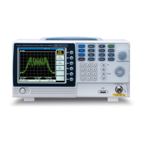
SPECTRUM ANALYSER AE-366B 1 INTRODUCTION Description The AE-366B is a low-cost, basic spectrum analyzer. The AE-366B has all the basic features of our more advanced models, but in a smaller package, designed especially for education. Figure 1. Main Features Performance: ►... -
Page 10: Package Content
USB 2.0 Host port for data storage. USB 2.0 Device port for the virtual com port communication. Package Content Opening the box Figure 2. Check that your package contains the following elements: AE-366B Analyser. Quick Start Guide. Mains cord for external DC charger. July 2018... -
Page 11: Getting Started
2 GETTING STARTED Appearance Front Panel Figure 3. LCD display: ► 640 X 480 color LCD display. The display shows the soft keys for the current function, frequency, amplitude and marker information. Function keys: ► function keys directly correspond to the soft keys on the right- hand side of display. - Page 12 Amplitude: Sets the amplitude reference level, scale and amplitude units. Autoset: Automatically searches the peak signal with maximum amplitude and displays it with appropriate horizontal and vertical scales. Marker: The Marker key is used to configure the markers, trace markers as well as other related functionality.
- Page 13 Power key: Turns the instrument on/off. ► Scroll wheel: Edit values, select listed items. ► Arrow keys: Increment/decrement values steps), ► select listed items. RF input RF input port. Accepts RF inputs. ► terminal: Maximum input: +30 dBm (+20 dBm measurable).
- Page 14 Rear Panel Figure 4. RS-232: RS232 9 pin DSUB port. ► USB B: USB B Device port. USB 1.1/2.0. ► VGA: video-out port. Supports SVGA ► (480X640). Power Socket: Power Socket:100~240V, 50/60Hz. ► 15W Max. Security Slot: Kensington-type security slot. ►...
- Page 15 Display Figure 5. Reference level: ► Displays the reference level. Marker Information: ► Displays marker information. Function menu: ► Displays the current function menu. Soft menu keys: ► The Soft menu keys are associated with the F1 to F6 function keys to the right of the display.
-
Page 16: First Time Use Instructions
Lastly, the Conventions sections will introduce you to the basic operating conventions used throughout the user manual. 2.2.1 Tilting the Stand The AE-366B has two adjustable tabs at the front that can be used to position the instrument into two preset orientations. Leaning Position: ►... -
Page 17: Power Up And Down
Figure 10. 2.2.3 Software Update The AE-366B allows the software to be updated by end-users. Before using the AE-366B, please check the PROMAX website or ask your local distributor for the latest software. The update file, MAIN1.BIN, must be placed in the root directory of a USB flash drive. -
Page 18: Usb Driver Installation
If the type B USB port on the rear panel is to be used for remote control, then the USB driver must be installed. Ensure the AE-366B is turned on. Connect the USB cable from the PC to the rear panel USB B port. Windows will automatically detect the AE-366B as a new device. 2-10 July 2018... -
Page 19: Restoring Default Settings
Follow the instructions to locate the AE-366B driver. To see if the driver has been successfully installed, you can check to see if the AE-366B is recognized by the Windows Device Manager when the AE-366B in connected to the PC. -
Page 20: Conventions
Conventions The following conventions are used throughout the user manual. Read the conventions below for a basic grasp of how to operate the AE-366B menu system and front panel keys. Soft Menu keys: ► function keys on the right side of the display correspond directly to the soft-menu keys on their left. - Page 21 Return to the Start When you have navigated down a menu ► of a Menu Tree: tree and you wish to return to the start of the menu tree, simply press the same Menu again. For example if you pressed: More Min Hold simply press...
- Page 22 The value of the parameter is shown at the bottom of the screen as it is edited. Figure 15. Back Space: Use the backspace key to delete the last character or number entered. Using the scroll wheel: Use the scroll wheel to alter the current value. Clockwise increases the value, anti-clockwise decreases the value.
-
Page 23: Basic Operation
3 BASIC OPERATION Frequency Settings 3.1.1 Center Frequency The center frequency function sets the center frequency and centers the display to the center frequency. Press Center and enter the frequency and unit. Range 0 kHz ~ 3 GHz Default: 1.5 GHz. Figure 16. -
Page 24: Center Frequency Step
To set the stop frequency, press Stop and enter the frequency and unit. Range: 0 kHz ~ 3 GHz. Default Start frequency: 0 Hz. Default Stop frequency: 3 GHz. Figure 17. NOTE: The start and stop frequency can change when the span settings are used. - Page 25 By default, the center frequency step size is equal to 10% of the span. Press Step and set the center frequency step size. Range: 1 kHz ~ 3 GHz. Figure 18. 3-17 July 2018...
-
Page 26: Span Settings
Span Settings 3.2.1 Span The Span function will set the frequency range of the sweep. The sweep will be centered around the center frequency. Setting the span will alter the start and stop frequencies. Press Span and enter the span frequency range and unit. -
Page 27: Zero Span
3.2.3 Zero Span The Zero Span function will set the frequency range of the sweep to 0 Hz and fixes the start and stop frequencies to the center frequency. The Zero Span function measures the time domain characteristics of the input signal at the center frequency. -
Page 28: Amplitude Settings
Amplitude Settings The vertical display scale is defined by the reference level amplitude, attenuation, scale and external gain/loss. Reference Level 3.3.1 The reference level defines the absolute level of the amplitude on the top graticule in voltage or power. Press Ref. -
Page 29: Amplitude Units
3.3.2 Amplitude Units The amplitude units can be set from dBm, dBmV or dBuV. Press Units… to change the amplitude units. Units: dBm, dBmV, dBuV. 3.3.3 Scale/Div Sets the logarithmic units for the vertical divisions. Press Scale repeatedly to select the vertical division units. -
Page 30: Autoset
Autoset The Autoset function searches the peak signals and picks the signal peak with the maximum amplitude, and then shows it in the display. 3.4.1 Using Autoset Autoset Press Amplitude: Over the full amplitude range. Span: Over the full span range. Figure 23. -
Page 31: Limiting The Autoset Vertical Search Range
3.4.2 Limiting the Autoset Vertical Search Range You can set the amplitude floor so that the signals lower than the setting will be ignored by the Autoset search. Press Amp.Floor and switch the range from Auto to Man. Enter the amplitude limit with the number pad and Enter key. Range: −50 to + 20 dBm. -
Page 32: Marker
Marker A Marker shows the frequency and amplitude of a waveform point. The AE-366B can activate up to 5 markers or marker pairs simultaneously. The marker table and peak table functions help editing and viewing multiple markers in a single display. -
Page 33: Activating A Marker
3.5.1 Activating a Marker There are two basic marker types, normal markers and delta markers. Normal markers are used to measure the frequency/time or amplitude of a point on the trace. Delta markers are used to measure the difference between a reference point and a selected point on the trace. -
Page 34: Activate A Delta Marker
3.5.1.2 Activate a Delta Marker Delta markers are marker pairs that measure the difference in frequency and amplitude between a reference marker and a delta marker. When delta markers are activated, the reference and delta marker appear at the position of the selected marker, or in the center of the display if the selected marker has not yet be activated. -
Page 35: Move Marker Manually
3.5.1.3 Move Marker Manually Press Marker and select a marker number. Use the left/right arrow keys to move the marker one screen division at a time or the use the scroll wheel to move the marker in fine increments (one pixel at a time). Figure 27. -
Page 36: Move Marker To Trace
Move marker to peak: ► Press To Peak Move marker to center: ► Press To Center Move marker to other positions: ► Press More Marker to… and select one of the preset positions: Marker to Start Marker to Stop Marker to Step Marker to Ref. -
Page 37: Turn All Markers On Or Off
More All Mrk Off and turn all the markers off. 3.5.3 Show Markers in Table The AE-366B has a Marker Table function to show all the active markers and measurements at once. Press More Marker Table and turn the marker table on. -
Page 38: Edit Markers In Marker Table
The display will split into two screens. The bottom half will show the Marker Table with the marker No. (normal, reference or delta), frequency and the amplitude of the marker. Figure 30. 3.5.3.1 Edit Markers in Marker Table While the Marker Table function is the active function, the position of each marker and delta marker can be edited within the marker table. -
Page 39: Peak Search
Enter the new position of the marker using the keypad and units keys. 3.5.4 Peak Search The Peak Search key is used to find trace peaks. The currently active marker is used in conjunction with the peak functions to mark the peaks that are found. Peaks can be sorted by frequency or amplitude in the peak table. -
Page 40: Search For Peaks
3.5.4.3 Search for Peaks key can be used to search for a number of different peaks. Next Peak: Searches for next highest peak visible on the display. Next Peak Right: Searches for the next peak to the right of the marker. Next Peak Left: Searches for the next peak to the left of the marker. -
Page 41: Peak Table
Figure 33. Next Peak Right. Figure 34. Next Peak Left. 3.5.5 Peak Table The Peak Table function will display up to 5 peaks. The amplitude and frequency for each peak is listed. Press More Peak Table and turn the peak table Press Peak Sort and set the sorting type: Freq: Sort by frequency in ascending order. - Page 42 The bottom-half of the screen shows the peak table with the peak marker no., frequency and amplitude. Figure 35. 3-34 July 2018...
-
Page 43: Measurement
Measurement This section describes how to use the automatic measurement modes. The AE-366B includes the following measurements: ACPR. OCBW. 3.6.1 Channel Analysis Overview Channel analysis measurement includes ACPR (adjacent channel power) and OCBW (occupied bandwidth) measurements. Parameters: ► Channel bandwidth: The frequency bandwidth the target channel occupies. -
Page 44: Acpr
3.6.1.1 ACPR Adjacent channel power refers to the amount of power leaked to the adjacent channel from the main channel. This measurement is a ratio of the main channel power to power in the adjacent channel. Figure 36. Operation: Setting up the main channel. ►... - Page 45 Turn ACPR off to return back to the normal mode. Figure 37. Press Channel Setup… and set the following: Main CH BW Set the bandwidth of the main channel. Main CH Space : Specify the channel spacing. NOTE: The main channel bandwidth and space settings are shown in the setup area at the bottom of the screen, not on the soft-key icon.
- Page 46 Operation: Setting up the adjacent channel(s). ► Press ADJCH Setup… to setup the adjacent channels: Adj CH BW 1 Sets the bandwidth of the 1st adjacent channel. Adj CH Offs 1 Sets the channel offset of the 1st adjacent channel. Adj CH BW 2 Sets the bandwidth of the 2nd adjacent channel.
-
Page 47: Ocbw
3.6.1.2 OCBW Occupied bandwidth measurements are used to measure the power of the occupied channel as a percentage to the power of the channel. Figure 40. Operation: Setting up the main channel. ► Press OCBW % and turn OCBW on. Any other measurement mode will automatically be disabled. - Page 48 Press Channel Setup… and set the following: Main CH BW Set the bandwidth of the main channel. Main CH Space : Specify the channel spacing. NOTE: The main channel bandwidth and space settings are shown in the setup area at the bottom of the screen, not on the soft-key icon. Figure 42.
-
Page 49: Limit Line Testing
Limit Line Testing The Limit Line function is used to set the upper or lower amplitude limits over the entire frequency range. The limit lines can be used to detect whether the input signal is above, below or within the limit lines. The limit lines can be manually edited using 10 frequency points from the start to the stop frequencies. -
Page 50: Creating A Limit (Point By Point)
High, Low. Press Edit Table and turn the edit table on. The AE-366B is split into two screens. The top screen shows the trace and the selected limit line (high or low) and the bottom screen shows the limit line table. -
Page 51: Pass/Fail Testing
Use the arrow keys to move the cursor to the frequency column of the desired point. Figure 45. Enter the new frequency and amplitude of the point using the keypad and the unit keys. Repeat steps 3-5 for the remaining points (A maximum of ten points). To delete the selected point, press Delete To delete all the points, press Delete All…... - Page 52 NOTE: Before pass/fail testing can begin, limit lines for the upper and/or lower limits must first be saved and activated. Press Pass/Fail to turn the testing on or off. The test result is updated in real-time at the bottom of the display. Pass: Fail: NOTE:...
-
Page 53: Bandwidth
Bandwidth BW key sets the resolution bandwidth (RBW). The resolution bandwidth and the sweep time are related. Please take into account how the sweep time is effected by the resolution bandwidth. 3.8.1 Resolution Bandwidth Setting (RBW) The RBW (Resolution Bandwidth) defines the width of the IF (intermediate frequency) filter that is used to separate signal peaks from one another. -
Page 54: Trace
Trace The AE-366B is able to set the parameters of up to 3 different traces on the display at once. Each trace is represented by a different color and is updated with each sweep. 3.9.1 Selecting a Trace Each trace (A, B, C) is represented by a different color. Trace A is green, trace B is orange and trace C is yellow. - Page 55 Blank: Clears the selected trace from the display and stores trace data. The trace data can be restored by pressing View Operation ► Press Trace and choose a trace. Trace: A, B, C. Select the trace type: Clear & Write Peak Hold View Blank...
-
Page 56: Trace Math
3.9.2 Trace Math Performs trace math from two traces (A, B) and stores the results in trace A or swaps the data from trace A to trace B. Math functions: A <--> B: Swaps the data from trace A to B and vice versa. A + B ->... - Page 57 Figure 48. Average:Off. Figure 49. Average:On (8x). 3-49 July 2018...
-
Page 58: Display
3.10 Display The Display key configures the basic display settings as well as the split screen modes. Adjusting the LCD Brightness 3.10.1 The LCD brightness levels can be adjusted to five pre-set levels. Press LCD Dimmer and use either the number pad, the scroll wheel or arrow keys to set the brightness. -
Page 59: Using The Video Out Port
3.10.3 Using the Video Out Port The AE-366B has a dedicated VGA terminal to output the display to an external monitor. The video output is always on. Output resolution: 480 x 640 (fixed). Connect external monitor rear panel terminal 3.10.4... - Page 60 Half-Lower: Half-Lower will put the spectrum analyzer into split screen mode. It will make the bottom sweep the active sweep and pause the top sweep. When Half-Lower is on, only the lower sweep settings can be edited. Alternate Sweep: This setting will alternate the sweep between the bottom and top spectrums.
-
Page 61: Save/Recall Files
3.11 Save/Recall Files The AE-366B can save and recall setup data, trace data and limit line data to and from internal memory. There are five memory locations for each save file type. These files cannot be saved to USB. The Hardcopy key can be used to save image files to a USB flash drive. -
Page 62: Save/Recall Trace Data
3.11.2 Save/Recall Trace Data The trace data can be saved/recalled for any of the A, B or C traces to/from one of 5 pre-set internal memory locations. The trace data cannot be recalled or saved to USB. When saving or recalling trace data from a split spectrum, only the active spectrum is saved/recalled. -
Page 63: Save/Recall Limit Lines
3.11.3 Save/Recall Limit Lines Upper and lower limit lines can be saved to one of 5 pre-set internal memory locations. The limit line data cannot be saved to USB. Save: To save the current upper and lower limit lines, press >... -
Page 64: Hardcopy Setup
NOTE: The file name will be automatically created in the following format:File name: SCRXX.bmpWhere XX is a number that is incremented each time the file is saved. WARNING: Do not remove the USB drive until the file has completed saving. 3.11.5 Hardcopy Setup The Hardcopy Setup key is used set the image file properties of the bitmap file... -
Page 65: System Settings
3.12 System Settings 3.12.1 System Information Description ► The System Information displays the following: Serial Number: XX digit serial number. HW Version: Hardware version. FW Version: Firmware version. SW Version: Software version. Language: Shows the language number as seen in the System>Language menu. Operation ►... -
Page 66: System Language
3.12.2 System Language The language option sets the icon display language. Press Language… to bring up the Language menu. Choose a system language. The language number is the number that will be displayed in the system information. 3-58 July 2018... -
Page 67: Remote Control
Data bit: 5, 6, 7, 8. The AE-366B can use either the type B USB port or the RS232 on the rear panel for remote control. When using the USB B port, the AE-366B uses a USB driver to simulate an RS232 connection with a PC via USB. -
Page 68: Remote Control Function Check
Panel Operation ► USB Connection: Connect a USB cable from the PC to the rear panel USB B port. RS232 Connection: Connect an RS232C cable from the PC to the rear panel RS232 port. Press Serial Port… Serial to enter the remote configuration. -
Page 69: Command Syntax
Command Syntax Compatible Standard: IEEE488.2 Partial compatibility. SCPI, 1999 Partial compatibility. Command Structure: SCPI (Standard Commands for Programmable Instruments) commands follow a tree-like structure, organized into nodes. Each level of the command tree is a node. Each keyword in a SCPI command represents each node in the command tree. - Page 70 Command Format: Figure 54. Command header. Space. Parameter 1. Optional space. Unit or suffix. Common Input/Return Parameters: Type Description Example <Boolean> Boolean logic 0, 1 <NR1> integers 0, 1, 2, 3 <NR2> decimal numbers 0.1, 3.14, 8.5 <NRf> any of NR1, 2 1, 1.5 <freq>...
-
Page 71: Command List
Command List 4.3.1 IEEE488.2 Standard Commands Name *IDN? Queries the manufacturer, model number, serial number, and Description firmware version of the instrument. Query *IDN? Syntax Return <string> Returns the instrument identification parameter 4.3.2 Sweep Commands Name Description Stops the sweep. Example Name Description... -
Page 72: Span Commands
Name meas:freq:st Description Sets or queries the start frequency. Syntax meas:freq:st<freq> Query meas:freq:st? Syntax Parameter <freq> Start frequency. Return <freq> Returns the start frequency and unit. parameter Example meas:freq:st 100mhz Sets the start frequency to 100MHz Query meas:freq:st? >100000 kHz example Name meas:freq:stp... -
Page 73: Amplitude Commands
4.3.5 Amplitude Commands Name meas:refl:unit Description Sets the reference level unit Syntax meas:refl:unit {1/2/3} Query meas:refl:unit? Syntax Parameter/ dBmV Return dBµV parameter Query meas:refl:unit? >1 example The reference level unit are dBm. Name meas:refl Description Sets or queries the reference level. meas:refl <refl>... - Page 74 Name meas:mark:off Description Sets which markers are turned off. Syntax meas:mark:off {<NR1>/all} Parameter <NR1> Marker number 1~5. All markers. Example meas:mark off 1 Turns marker 1 off. Name meas:mark:norm Description Sets the selected marker to normal mode. Syntax meas:mark:norm<NR1> Parameter <NR1>...
- Page 75 Name meas:mark:delta:freq? Description Queries the (relative) frequency of the selected delta marker. Query meas:mark:delta:freq <NR1>? syntax Marker number 1~5. Parameter <NR1> Return Returns the relative frequency and unit of the <freq> selected delta marker. parameter Example meas:mark:norm:freq1? >12.0kHz. Name meas:mark:delta:level? Description Queries the amplitude of the selected delta marker.
-
Page 76: Trace Commands
Name meas:mark:trace Description Sets the selected marker to the selected trace. Syntax meas:mark:topeak <NR1> <trace> Parameter <NR1> Marker number 1~5. <trace> Auto (auto assign a trace) TraceA TraceB TraceC Example meas:mark:trace 1 2 Sets marker 1 to trace B. 4.3.7 Trace Commands Name meas:tra:val1:val2... -
Page 77: Power Measurement Commands
Name meas:tra:read Description Returns the all the trace data for the selected trace. Syntax meas:tra:read? <trace> Parameter <trace> Trace A Trace B Trace C All traces. Return <trace Comma separated data values encapsulated in data> brackets. I.e., {-92, -91, -90, ..-81} parameter Example meas:tra:read?1... - Page 78 Name meas:acpr:upper? Description Returns the upper ACPR measurement result for the selected channel offset (offset 1 or 2). Query meas:acpr:upper? {1/2} syntax Parameter Channel offset 1 Channel offset 2 Return <NR2> Returns the ACPR measurement result. parameter Example meas:acpr:lower?1 >-11.8 Name meas:ocbw Description...
-
Page 79: Limit Line Commands
4.3.9 Limit Line Commands Name meas:Imtline:passfail Description Turns the Pass/Fail test on/off or queries its state. Syntax meas:Imtline:passfail {on/off} Query meas:Imtline:passfail syntax Parameter Turns the pass/fail test on. Turns the pass/fail test off. Return Fail parameter Pass meas:Imtline:passfail? Query >0 Example Name meas:Imtline:on... -
Page 80: Display Commands
Name con:rbw:man Description Sets the RBW for manual mode. Syntax Con:rbw:man {0/1/2/3/} Return <NR1> 100kHz 300kHz parameter 1MHz Example con:rbw:man1 Sets the RBW to 100kHz. Name con:rbw:mode? Description Returns the RBW mode. Query con:rbw:mode? Syntax Return auto Auto mode parameter manual Manual mode con:rbw:mode? -
Page 81: Preset Commands
4.3.12 Preset Commands Name con:preset Description Loads the factory default settings. This is the equivalent to pressing the Preset key. con:preset Syntax 4.3.13 System Commands Name con:sys:ser? Description Returns the serial number. Query con:sys:ser? syntax Return <string> Returns the serial number in the following format: XXXXXXXX parameter Example... -
Page 82: Faq
► I connected the signal but it does not appear on screen. Run Autoset and let the AE-366B find the best display scale for your target signal. Press the Autoset key, then press Autoset The trace is updated too slowly on the screen. -
Page 83: Specifications
6 SPECIFICATIONS Specifications AE-366B FREQUENCY Frequency Range Setting Range 150 kHz to 3 GHz. Center Frequency Setting Resolution 0.1 MHz. Accuracy within ± 50kHz (frequency span: 0.3 GHz to 2.6 GHz, 20 ± 5 °C). Frequency Span Setting Range 1 MHz to 3 GHz. - Page 84 SWEEP Sweep Time Setting Range 300 ms to 8.4 s, auto (not adjustable). Accuracy within ± 2% (frequency span: full span). GENERAL Communication Display 640 x 480 RGB color LCD. Interface RS-232C Sub-D female-D 9 pins USB Connector USB Host/Device full speed supported. USB Format Supports FAT/FAT32 only.
-
Page 85: Default Settings
Default Settings Frequency ► Center Frequency: 1.5GHz Start Frequency: 0Hz Stop Frequency: 3GHz CF Step: Auto Span ► Span: 3GHz Amplitude ► Reference level: -30.0dBm Scale Div: 10 Units: dBm Autoset ► Amp.Floor: Auto Span: Auto Marker ► Marker: Off Peak Search ►... - Page 86 Trace ► Trace: A: Clear&Write Average: Off Display ► Full Display: Active Display line: off Memory ► Preset ► Hardcopy ► Hardcopy Setup ► Ink Normal System ► 6-78 July 2018...
Need help?
Do you have a question about the AE-366B and is the answer not in the manual?
Questions and answers