Advertisement
Quick Links
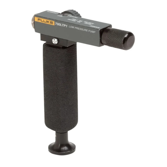
Introduction
The Fluke-700LTP-1 Low-Pressure Test Pump is a
portable, dual source of vacuum and pressure. Each pump
incorporates a vacuum and pressure selector and fine
adjustment control. The pump has the following
specifications:
•
Output pressure: 0 to 100 psi / 0 to 6.9 bar
•
Output vacuum: 0 to -13 psi / 0 to -900 mbar
•
Exposed Materials: Aluminum, silicon, neoprene,
stainless steel, Buna-N
•
Adjustment: Fine volumetric pressure and vacuum
adjuster
•
Dimensions: 150 mm x 100 mm
•
Weight: 226 grams or .5 lbs (pump only)
Box Contents
•
Fluke 700LTP-1 Low-pressure Test Pump
•
1/8 in NPT male/female tee
•
(2) 1 m hoses
•
(4) 1/8 in NPT male quick connects
•
(2) 1/8 NPT female to 1/4 in BSP female
•
Seal Kit
•
Instruction Sheet
Contacting Fluke
To contact Fluke or for service, call one of the following
telephone numbers:
USA: 1-888-44-FLUKE (1-888-443-5853)
Canada: 1-800-36-FLUKE (1-800-363-5853)
Europe: +31 402-675-200
Japan: +81-3-3434-0181
Singapore: +65-738-5655
Anywhere in the world: +1-425-446-5500
Or, visit Fluke's Web site at www.fluke.com.
PN 2811813 April 2007
© 2007 Fluke Corporation. All rights reserved. Printed in U.S.A.
Fluke-700LTP-1
Low-Pressure Test Pump
1
2
8
7
Pressure/vacuum release valve- Turn valve counter-
clockwise for vacuum, clockwise for pressure and
A
centered for release.
Fine adjustment control- Turn in or out to increase or
B
decrease pressure accordingly.
Master and test port tee
C
Quick-fit connectors
D
Hose
E
1/8 in NPT female to 1/4 in BSP female fitting
F
Pump Handle. If the pump has not been used for a
while, there may be some resistance on the first
G
stroke.
Cleanout ports (2)- See cleanout instructions
H
Figure 1. Features
Guidelines for Use
1.
Connect a pressure calibrator or pressure module to
the quick-fit connector (item D) at the end of one of the
flexible hoses (item E).
2.
Connect the unit under test to the quick-fit connector
(item D) at the end of the second flexible hose (item
E), choosing correct adapters (item F) and seals.
3.
Turn the fine adjustment control to mid-range.
4.
Set control valve to pressure.
Operate handle (item G) until the pressure is close to
5.
the required value.
Instruction Sheet
3
4
6
5
eus01f.eps
®
1
Advertisement

Subscribe to Our Youtube Channel
Related Manuals for Fluke 700LTP-1


Summary of Contents for Fluke 700LTP-1
- Page 1 Instruction Sheet Cleanout ports (2)- See cleanout instructions Contacting Fluke Figure 1. Features To contact Fluke or for service, call one of the following telephone numbers: Guidelines for Use USA: 1-888-44-FLUKE (1-888-443-5853) Connect a pressure calibrator or pressure module to...
- Page 2 LIMITED WARRANTY AND LIMITATION OF LIABILITY Gently remove the spring and o-ring assembly. This This Fluke product will be free from defects in material and workmanship for includes several small components. Remove with care. one year from the date of purchase. This warranty does not cover fuses, See Figure 2.
Need help?
Do you have a question about the 700LTP-1 and is the answer not in the manual?
Questions and answers