Advertisement
Quick Links
Advertisement

Subscribe to Our Youtube Channel
Related Manuals for Fortis MR-400


Summary of Contents for Fortis MR-400
- Page 1 MAGNETIC FLYWHEEL FULL MOTION ROWING MACHINE (MR-400) FSMFWMR400A...
-
Page 3: Safety And Warnings
SAFETY & WARNINGS Read all of the instructions in this guide before using this product. Retain this guide for future reference. Do not skip, substitute or modify any steps or procedures in this guide, as doing so could result in personal injury or product damage. •... - Page 4 • Be careful when lifting and moving the equipment. Always use proper lifting technique and seek assistance if necessary. • Your equipment is intended for use in cool, dry conditions. You should avoid storage in extreme cold, hot or damp areas as this may lead to corrosion and other related problems.
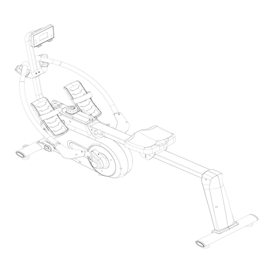
- Page 5 OVERVIEW...
- Page 6 Part Description Part Description Computer Bolt M8 x 20 x S6 Washer d8 x Φ16 x 1.5 Computer Seat Screw M5 Front Stabiliser Bolt M8 x 90 x 20 x S13 End Cap ZT80 x 40 Transportation Wheel Washer d8 x Φ16 x 1.5 Φ48 x 22 x Φ8 x 22 Nut M8 x H7.5 x S13 Nut M8 x H7.5 x S13...
- Page 7 Part Description Part Description Left Support Plate Screw M5 x 5 Shaft Sleeve U Board 76L/R Combination Bolt Φ14 x 44 x 17 x M12 Wheel Φ40 x 92 x 16 Screw ST4.2 x 19 x Bearing 608Z Φ8.4 Spacer d8 x Φ15 x 4 Rowing Rod Limited Cushion of Magnet Φ15 x 7...
- Page 8 Part Description Part Description Spring Φ1.5 x Φ14.5 x 61 Screw M6 x 8 x Φ12 x N21 Screw M6 x 10 x Φ12 Small Chain wheel Magnet Location 45.5 x Cover 130 x 10.5 Magnet Cover Screw ST3 x 10 x Φ5.6 Trunk Wire 1 Adjusting U Plate Bolt M8 x 16 x S6...
- Page 9 ASSEMBLY Step 1: Attach Front Stabiliser ( 27 ) to Main Frame ( 13 ) with x2 Bolts ( 25 ) and x2 Washers ( 26 ). Tighten and secure with the Allen Wrench ( B ).
- Page 10 Step 2: Loosen T Knob ( 22 ) as shown in Figure C and pull outward. Next, rotate Computer Joint Tube ( 7 ) to the desired position and screw T Knob ( 22 ) into the hole. Finally, adjust Computer ( 1 ) up and down to the proper angle.
- Page 11 Step 3: Loosen x4 Screws ( 60 ) from Left & Right Shaft Sleeve Combinations ( 76L/R ) with Spanner ( A ). Remove x2 Bolts ( 77 ) and 2 Nuts ( 72 ) from Left & Right Shaft Sleeve Combinations ( 76L/R ) with Spanner ( D ).
- Page 12 Step 4: Insert Seat ( 45 ) to Sliding Rail ( 35 ). Attach Limited Pad ( 40 ) to Sliding Rail ( 35 ) with Screw ( 42 ) and Washer ( 41 ). Tighten and secure with the Spanner ( A ).
- Page 13 Step 5: Attach Rear Supporting Tube ( 132 ) to Sliding Rail ( 35 ) with x4 Bolts ( 128 ), x4 Spring Washers ( 46 ) and x4 Washers ( 26 ). Tighten and secure with the Allen Wrench ( B ). Attach Rear Stabiliser ( 34 ) to Rear Supporting Tube ( 132 ) with x2 Bolts ( 25 ) and x2 Washers ( 26 ).
- Page 14 Step 6: Attach Left & Right Covers ( 59L & 59R ) to Sliding Rail ( 35 ) and Rear Supporting Tube ( 132 ), then lock Left & Right Covers ( 59L & 59R ) with x2 Screws ( 61 ). Tighten and secure with the Spanner ( A ).
- Page 15 Step 7: Attach Sliding Rail ( 35 ) to Main Frame ( 13 ) using Bolt ( 36 ) and Screw ( 37 ). Tighten and secure with Allen Wrench ( B ) and Allen Wrench ( C ). Then insert Pull Pin ( 38 ). Next, attach the top of Sliding Rail ( 35 ) to Main Frame ( 13 ) using L Knob ( 17 ).
- Page 16 Step 8: Open the battery cover on the back of Computer ( 1 ), then put x2 “AAA” batteries into the battery case. Make sure the (-) end of the battery goes to the spring end in the battery compartment, then put the battery cover back.
-
Page 17: Before First Use
BEFORE FIRST USE Pedal Strap Adjustment The Pedal Strap ( 137 ) is adjustable and can be adjusted to fit the user’s foot size. Directions on how to loosen and tighten the straps are shown in Figures A and B. Figure A Loosen Pull... - Page 18 Adjusting the Resistance of the Rowing Rod The resistance is different at positions A, B, C, etc. The closer you are to positions A, the lighter the resistance. Adjusting the Balance In order to achieve a smooth and comfortable ride, you must ensure that the stability of the rower is secured.
-
Page 19: Operation
OPERATION Key Function: MODE: Press this button to change the display or to choose a program. SET: In the setting mode, press this button to increase the setting value for TIME, COUNT and CAL. Reset: In setting mode, press this button to reset the value for TIME, COUNT and CAL. In monitor mode, hold this button for 3 seconds to reset all values to zero. - Page 20 Moving the Rower To move the rower, lift up Rear Stabiliser ( 34 ) until the Transportation Wheels ( 29 ) on Front Stabiliser ( 27 ) touch the ground. Once the Transportation Wheels ( 29 ) are on the ground, you can transport the rower to the desired location with ease.
- Page 21 Folding the Rower When not in use, the rower can be folded to save space. Disassemble L Knob ( 17 ) and pull out Pull Pin ( 38 ) from Main Frame ( 13 ). Lift the Sliding Rail ( 35 ) up 90 degrees. Shown in Figure A.
- Page 22 Battery Replacement To replace the batteries, open the battery cover on the back of the Computer ( 1 ). Remove the batteries and replace with new “AAA” batteries. Make sure the (-) end of the battery goes to the spring end in the battery compartment. Put the cover back. When changing batteries, always replace both with new batteries.
- Page 23 NOTES...
- Page 24 Need more information? We hope that this user guide has given you the assistance needed for a simple set-up. For the most up-to-date guide for your product, as well as any additional assistance you may require, head online to help.kogan.com...
Need help?
Do you have a question about the MR-400 and is the answer not in the manual?
Questions and answers