
Subscribe to Our Youtube Channel
Related Manuals for Fortis MR-500A


Summary of Contents for Fortis MR-500A
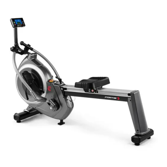
- Page 1 AUTOMATIC VARIABLE RESISTANCE MAGNETIC FLYWHEEL FULL MOTION ROWING MACHINE (MR-500A) FSAEMR500AA...
-
Page 3: Safety And Warnings
SAFETY & WARNINGS Read all the instructions in this guide before assembling or using this product. Do not skip, substitute, or modify any steps or procedures in this guide, as doing so could result in personal injury or product damage. Retain this guide for future reference. •... - Page 4 • Do not place fingers or any other objects into moving parts of the exercise equipment. • Do not use the corrosive cleaning agents, to avoid the liquid from entering the equipment. • Be careful when lifting and moving the equipment. Always use proper lifting technique and seek assistance if necessary.
- Page 5 COMPONENTS Main Frame (x1) Computer (x1) Adapter (x1) Covers (x2) Seat (x1) Rowing Rods (x2) Rear Stabiliser (x1) Pedals (x2) Covers (x2) Front Stabilizer (x1) Aluminium Rail (x1) Covers (x2) User Guide (x1) Hardware Pack Hardware Packs (x2) Computer Joint Tube (x1) Rowing Rod Pad (x1)
- Page 6 OVERVIEW...
- Page 8 Part Description Part Description Strap Fixed Board t4.0 x 12 x Console Console Bracket 28 (L/R) Rowing Rod Pad Nut M8 x H7.5 x S13 Screw M12 x 20 x S8 Washer d8 x Φ16 x 1.5 Screw ST4.2 x 19 x Φ8 Spring Washer d8 Seat Bolt M8 x 90 x 20 x S6...
- Page 9 Part Description Part Description Rectangular Steel 6 x 4 x Adaptor Washer d12 x Φ36.5 x 3.0 54 (L/R) shaft sleeve combination Bearing Φ62 x 16 x Φ30 Nut M12 x H11 x S19 CSK30PP Screw M5 x 5 Bolt M8 x 10 x S6 Rubber End Cap 84.5 x Trunk Wire 2 49.5 x 9.7...
- Page 10 Part Description Part Description Idler Wheel Shelf 1 Nut M10 x H9.5 x S17 Screw M8 x 15 x Φ10 x 5 x Nut M8 x H5.5 x S14 Limited Bracket 27 x 54 x Washer d12 x Φ17 x 0.5 Limited Block 51.3 x 28.5 x Bearing 6001-2RS CXSH 18 PP...
- Page 11 ASSEMBLY Step 1: Remove pre-assembled Protected Tubes (F) & (G) and Bolt (82) from the Main Frame (10) with Spanner (C). Reserve the Protected Tubes.
- Page 12 Step 2: Attach the Foot Pad (19) to the Front Stabilizer (11) and Rear Stabilizer (74).
- Page 13 Step 3: Attach the Front Stabilizer (11) to the Main Frame (10) using Screws (17), Spring Washers (5) and Washers (16) with Spanner (C). Remove pre-assembled Screw (30) from the Cover (61 L/R) with the Spanner (A). Attach the Cover (61L/R) to the Main Frame (10) using Screws (30) and Spanner (A). Attach the Pedal Support (20 L/R) to the Main Frame (10) using Screws (29), Spring Washers (138) and Washers (60).
- Page 14 Step 4: Connect Trunk Wire 1 (8) to Trunk Wire 2 (83). Insert the Computer Joint Tube (9) into the Main Frame (10). Connect the Computer Joint Tube (9) and Rod Holder (62) on the Main Frame (10) with Screws (82). Loosen the pre-assembled Screw (7) and Washer (47) on the back of the Console (1) with Spanner (A).
- Page 15 Step 5: Loosen the pre-assembled Bolt (52) and Nut (81) from the Shaft Sleeve Combination (54) using Spanner (D). Put the Rowing Rod (45) into the Shaft Sleeve Combination (54), adjust to the right position, then fasten with Bolts (52) and Nuts (81). Place Rowing Rod (45) on the Rowing Rod Pad (28 L/R).
- Page 16 Step 6: Slide the Seat (31) onto the Aluminium Rail (64). Fasten the Limited Bushing (70) with Limited Axle (69), Washer (71) and Screw (72) to the Aluminium Rail (64). Attach the rear Stabilizer (74) to the Aluminium Rail Support Frame (78) using Screws (17), Spring Washers (5) and Washers (16).
- Page 17 Step 7: Connect the Inductor (66) to the Trunk Wire 2 (83). Slide the Aluminium Rail into the U- shaped part on the Main Frame (10) and fasten the rail with Bolt (132), Washer (133) and Nut (134). Secure the rail with the Main Frame (10) using the L Bolt (59).
- Page 18 Step 8: Before using the equipment, connect Adaptor (79) to the Main Frame (10). Then insert the plug into the power socket.
-
Page 19: Before You Use
BEFORE YOU USE Pedal Strap Adjustment The length of strap can be adjusted to the size of the foot. The below image shows the direction to loosen and tighten the strap. Loosen Tighten Pedal Adjustment Remove the Pedal (21) from the Pedal Fixed Board (24). Pull it up and down as per your preference. - Page 20 Aluminium Rail Folding Push the Seat (31) to the front end of the Aluminium Rail (64). Remove the L bolt (59) on the Main Frame (10) to make the Aluminium Rail (64) rotate freely. Turn up the Aluminium Rail (64) and fix the Aluminium Rail (64) on the Main Frame (10) with L bolt (59).
-
Page 21: Operation
OPERATION The equipment has 17 programs as follows: Manual Program (1 Program) Preset Program Profile (10 Programs: P1 – P10) • P1: ROLLING, P2: VALLEY • P3: FATBURN, P4: RAMP... - Page 22 • P5: MOUNTAIN, P6: INTERVAL • P7: CARDIO, P8: ENDURANCE • P9: SLOPE, P10: RALLY...
- Page 23 User Setting Programs (5): CUSTOM 1 to CUSTOM 5 (P11 ~ P15) Record the user's data of User Setting Programs. Display Count (RPM), TIME and WATT, CAL and DIST at the same time. The computer will turn off automatically if there is no operation for more than 4 minutes.
- Page 24 Functions ENTER • In the STOP mode, press ENTER button select a program. Depending on the setting value the related window displays. When you choose the program, press ENTER to confirm. While setting, press ENTER to confirm the value that you would like to preset.
- Page 25 Using the Computer Step 1: Turn on the computer. • Connect to the adaptor to a power outlet and turn on the power supply. • The computer will beep and enter the initial mode. Step 2: Select a program and set a value. •...
- Page 26 • User Profile Programs: CUSTOM1~CUSTOM5(P11-P15) Press UP, DOWN button to select the user. Press ENTER to confirm your choice and enter the time setting window. The time display will flash, and then press UP, DOWN button to set up the desired time to do the exercise.
-
Page 27: Specifications
SPECIFICATIONS Adaptor Input Voltage AC 100-240V Output Power DC 9V 1A... - Page 28 Need more information? We hope that this user guide has given you the assistance needed for a simple set-up. For the most up-to-date guide for your product, as well as any additional assistance you may require, head online to help.kogan.com...
Need help?
Do you have a question about the MR-500A and is the answer not in the manual?
Questions and answers