Advertisement
Quick Links
Advertisement

Related Manuals for Fortis WATER & MAGNETIC HYBRID MR-600


Summary of Contents for Fortis WATER & MAGNETIC HYBRID MR-600
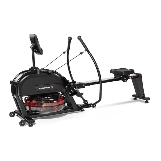
- Page 1 WATER & MAGNETIC HYBRID FULL MOTION ROWING MACHINE (MR-600) FSWMHMR600A...
-
Page 3: Safety And Warnings
SAFETY & WARNINGS Read all of the instructions in this guide before using this product. Retain this guide for future reference. Do not skip, substitute or modify any steps or procedures in this guide, as doing so could result in personal injury or product damage. •... - Page 4 • Be careful when lifting and moving the equipment. Always use proper lifting technique and seek assistance if necessary. • Your equipment is intended for use in cool, dry conditions. You should avoid storage in extreme cold, hot or damp areas as this may lead to corrosion and other related problems.
- Page 5 OVERVIEW...
- Page 6 Part Description Qty. Part Description Qty. Main frame Shaft Sleeve Rail Bolt M10 x 60 x 47 x 13 x S6 Left Pedal Cover 314 x 71 x 63.5 Screw ST4.2 x 19 x Ф11 Right Pedal Rowing Rod Cushion 60 x 40 x 15.2 Console Bolt M8 x 20 x S6 Seat...
- Page 7 ASSEMBLY Step 1: Lift up the front post ( 11 ) in the main frame ( 1 ). Take x2 bolt ( 12 ), x2 washer ( 13 ) and x2 washers ( 14 ) through the left pedal ( 3 ). Then secure the left pedal ( 3 ) to the corresponding hole of main frame ( 1 ) using the spanner ( A ).
- Page 8 Step 2: Attach the rowing rod ( 5 ) to the shaft sleeve ( 17 ), take the bolt ( 18 ) through the hole matching rowing rod ( 5 ) and shaft sleeve ( 17 ). Then attach washer ( 31 ) and nut ( 32 ), secure with spanner ( A ) and spanner ( D ).
- Page 9 Step 3: Remove the pre-installed cushion ( 21 ) and x2 screws ( 20 ) from the rail ( 2 ) using spanner ( C ). Slide the seat ( 7 ) into the rail ( 2 ). Secure the cushion ( 21 ) and x2 screws ( 20 ) to the rail ( 2 ) using spanner ( C ).
- Page 10 Step 4: Attach the rear stabiliser ( 10 ) to the rail ( 2 ) with x4 bolts ( 22 ), x4 washers ( 23 ) and x4 washers ( 24 ). Then fasten it using spanner ( B ).
- Page 11 Step 5: Fasten the L/R cover ( 9 ) to the rail ( 2 ) and rear stabiliser ( 10 ) separately. Put the x4 screw ( 25 ) through the hole of L/R cover ( 9 ). Then fasten it to rear stabiliser ( 10 ) using spanner ( C ).
- Page 12 Step 6: Connect trunk wire and sensor wire, as shown (Figure A). Insert the rail ( 2 ) to the main frame ( 1 ). Put the bolt ( 26 ) through the hole of main frame ( 1 ), then fasten with nut ( 28 ) and washer ( 27 ) to the main frame ( 1 ) by spanner ( D ).
- Page 13 Step 7: Take out the x4 screw ( 29 ) from the back of console ( 6 ) by spanner ( C ). Connect trunk wire with the wire of console ( 6 ), then secure console ( 6 ) into console Seat ( 30 ) with x4 screws ( 29 ) by spanner ( C ).
-
Page 14: Before First Use
BEFORE FIRST USE Pedal strap adjustment The Pedal Strap is adjustable and can be adjusted to fit the user’s foot size. Directions on how to loosen and tighten the straps are shown (Figures A & B). Loosen Figure A Figure B Tighten Tension adjustment Rotate the Tension Knob clockwise to increase the level of resistance. - Page 15 Water resistance Water resistance is set between 1 to 6 levels, which is indicated by the water level sticker on the water tank. The resistance depends on how much water is in the tank. Level 1 being the lowest and Level 6 being the highest. Raising the water level will increase the resistance.
-
Page 16: Operation
OPERATION Key Function: MODE: Press this button to change the display or to choose a program. SET: In the setting mode, press this button to increase the setting value for TIME, COUNT and CAL. Reset: In setting mode, press this button to reset the value for TIME, COUNT and CAL. In monitor mode, hold this button for 3 seconds to reset all values to zero. - Page 17 Folding the Rower When not in use, the rower can be folded to save space. Fold the rail ( 2 ) up until the foot pad of main frame ( 1 ) touch the ground. The seat ( 7 ) will slide down when the rail ( 2 ) is folded. Ensure care is taken. Foot Pad Moving the Rower To move the rower, lift up Rear Stabiliser ( 10 ) until the Transportation Wheels on main frame...
- Page 18 Water Tank Adding Water: Remove the tank cover mounted on the mainframe ( 1 ). Fill water as shown (Figure A). Insert the Manual water pump ( 8 ) into the water and the other end into the tank of the main frame ( 1 ). Squeeze the head of Manual water pump ( 8 ), so water can be added to the water tank according to the water level marked on water tank.
- Page 19 NOTES...
- Page 20 Need more information? We hope that this user guide has given you the assistance needed for a simple set-up. For the most up-to-date guide for your product, as well as any additional assistance you may require, head online to help.kogan.com...
Need help?
Do you have a question about the WATER & MAGNETIC HYBRID MR-600 and is the answer not in the manual?
Questions and answers