
Subscribe to Our Youtube Channel
Related Manuals for Ford FG9250E


Summary of Contents for Ford FG9250E
- Page 1 Model: FG9250E ITEM#: F10750E991 Generator OPERATOR’S MANUAL Warning: The Engine Exhaust from this product contains chemicals known to the State of California to cause cancer, birth defects or other reproductive harm. www.fordpower.cc...
-
Page 2: Table Of Contents
TABLE OF CONTENTS Introduction. NNNNNNNNNNNNNNNNNNNNNNNNNNNNNNNNNNNNNNNNNNNNNNNNNNNNNNNNNNNNNNNNNNNNNNNNNNNNNNNNNNNNNNNNNNNNNNNNNNNNNNNNNNNNNNNNNNNNNNNNNNNNNNNNNNNNNNNNNNNNNNNNNNNNNNNNNNNNNNNNNNNNNNNNNNNN 3 Product Specifications. NNNNNNNNNNNNNNNNNNNNNNNNNNNNNNNNNNNNNNNNNNNNNNNNNNNNNNNNNNNNNNNNNNNNNNNNNNNNNNNNNNNNNNNNNNNNNNNNNNNNNNNNNNNNNNNNNNNNNNNNNNNNNNNNNNNNNNNNNNNNNNNN 3 Parts Ordering / Customer Service. NNNNNNNNNNNNNNNNNNNNNNNNNNNNNNNNNNNNNNNNNNNNNNNNNNNNNNNNNNNNNNNNNNNNNNNNNNNNNNNNNNNNNNNNNNNNNNNNNNNNNNNNNNNNNNNNNNNNNNNNNNNNN 3 Safety Rules. NNNNNNNNNNNNNNNNNNNNNNNNNNNNNNNNNNNNNNNNNNNNNNNNNNNNNNNNNNNNNNNNNNNNNNNNNNNNNNNNNNNNNNNNNNNNNNNNNNNNNNNNNNNNNNNNNNNNNNNNNNNNNNNNNNNNNNNNNNNNNNNNNNNNNNNNNNNNNNNNNNNNNNNNNNN 4 Safety Symbols. NNNNNNNNNNNNNNNNNNNNNNNNNNNNNNNNNNNNNNNNNNNNNNNNNNNNNNNNNNNNNNNNNNNNNNNNNNNNNNNNNNNNNNNNNNNNNNNNNNNNNNNNNNNNNNNNNNNNNNNNNNNNNNNNNNNNNNNNNNNNNNNNNNNNNNNNNNN 4 Safety Instructions .NNNNNNNNNNNNNNNNNNNNNNNNNNNNNNNNNNNNNNNNNNNNNNNNNNNNNNNNNNNNNNNNNNNNNNNNNNNNNNNNNNNNNNNNNNNNNNNNNNNNNNNNNNNNNNNNNNNNNNNNNNNNNNNNNNNNNNNNNNNNNNNNNNNNN 4 Features.NNNNNNNNNNNNNNNNNNNNNNNNNNNNNNNNNNNNNNNNNNNNNNNNNNNNNNNNNNNNNNNNNNNNNNNNNNNNNNNNNNNNNNNNNNNNNNNNNNNNNNNNNNNNNNNNNNNNNNNNNNNNNNNNNNNNNNNNNNNNNNNNNNNNNNNNNNNNNNNNNNNNNNNNNNNNNNNNNNN 7 Assembly. NNNNNNNNNNNNNNNNNNNNNNNNNNNNNNNNNNNNNNNNNNNNNNNNNNNNNNNNNNNNNNNNNNNNNNNNNNNNNNNNNNNNNNNNNNNNNNNNNNNNNNNNNNNNNNNNNNNNNNNNNNNNNNNNNNNNNNNNNNNNNNNNNNNNNNNNNNNNNNNNNNNNNNNNNNNNNNNN 9 Unpacking .NNNNNNNNNNNNNNNNNNNNNNNNNNNNNNNNNNNNNNNNNNNNNNNNNNNNNNNNNNNNNNNNNNNNNNNNNNNNNNNNNNNNNNNNNNNNNNNNNNNNNNNNNNNNNNNNNNNNNNNNNNNNNNNNNNNNNNNNNNNNNNNNNNNNNNNNNNNNNNNNNNN 9 Packing List . NNNNNNNNNNNNNNNNNNNNNNNNNNNNNNNNNNNNNNNNNNNNNNNNNNNNNNNNNNNNNNNNNNNNNNNNNNNNNNNNNNNNNNNNNNNNNNNNNNNNNNNNNNNNNNNNNNNNNNNNNNNNNNNNNNNNNNNNNNNNNNNNNNNNNNNNNNNNNN 9 Attaching Wheels.NNNNNNNNNNNNNNNNNNNNNNNNNNNNNNNNNNNNNNNNNNNNNNNNNNNNNNNNNNNNNNNNNNNNNNNNNNNNNNNNNNNNNNNNNNNNNNNNNNNNNNNNNNNNNNNNNNNNNNNNNNNNNNNNNNNNNNNNNNNNNNNNNNNNNN... -
Page 3: Introduction. Nnnnnnnnnnnnnnnnnnnnnnnnnnnnnnnnnnnnnnnnnnnnnnnnnnnnnnnnnnnnnnnnnnnnnnnnnnnnnnnnnnnnnnnnnnnnnnnnnnnnnnnnnnnnnnnnnnnnnnnnnnnnnnnnnnnnnnnnnnnnnnnnnnnnnnnnnnnnnnnnnnnnnnnnnnnn
INTRODUCTION Thank you for purchasing this superior quality portable generator from Ford Power Equipment. When operating and maintaining this product as instructed in this manual, your generator will give you many years of reliable service. Product Specifications: This generator is an engine-driven, revolving field, alternating current (AC) portable generator. It is designed to supply electrical power to operate tools, appliances, camping equipment, lighting, or serve as a back up power source during power outages. -
Page 4: Safety Rules. Nnnnnnnnnnnnnnnnnnnnnnnnnnnnnnnnnnnnnnnnnnnnnnnnnnnnnnnnnnnnnnnnnnnnnnnnnnnnnnnnnnnnnnnnnnnnnnnnnnnnnnnnnnnnnnnnnnnnnnnnnnnnnnnnnnnnnnnnnnnnnnnnnnnnnnnnnnnnnnnnnnnnnnnnnnn
SAFETY RULES Safety Symbols Indicates a potentially hazardous WARNING! situation which could result in serious injury or death if not avoided. Indicates a potentially hazardous CAUTION! situation which could result in damage to equipment or property. Toxic Fumes Risk of fire Risk of explosion Risk of electric shock Hot surface... - Page 5 SAFETY RULES Never exceed generator’s wattage / amperage capacity. This could damage the generator WARNING! and / or connected electrical devices. • Check operating voltage and frequency requirements of all electrical devices prior to plugging them into the generator. Never start or stop engine with electrical devices plugged in to the receptacles. Failure to do WARNING! so could damage the generator and / or connected electrical devices.
- Page 6 Never transport or make adjustments to this unit while it is running. • Never insert objects through cooling slots. Never operate this unit if there are any broken or missing parts and only use Ford Power WARNING! Equipment replacement parts specifically designed for this unit.
-
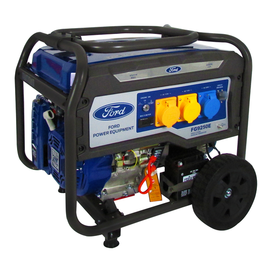
Page 7: Features.nnnnnnnnnnnnnnnnnnnnnnnnnnnnnnnnnnnnnnnnnnnnnnnnnnnnnnnnnnnnnnnnnnnnnnnnnnnnnnnnnnnnnnnnnnnnnnnnnnnnnnnnnnnnnnnnnnnnnnnnnnnnnnnnnnnnnnnnnnnnnnnnnnnnnnnnnnnnnnnnnnnnnnnnnnnnnnnnnnn
FEATURES A - ON/OFF Start Switch E - 120V / 240V 30 Amp Twist Lock (L14-30) B - Engine ON/OFF Switch (Must be ON to start engine) F - 12V DC Receptacle C - Hour Meter G - Circuit Protectors D - Two 120V AC 20 Amp GFCI Duplex Receptacles H - Panel Thumb Screws... - Page 8 FEATURES I - Fuel Tank Vapor Vent P - Fuel Tank J - Handle Q - Fuel Valve (ON/OFF) K - Removeable Control Panel R - No Flat Foam Filled Tires L - Choke Lever S - Battery M - Recoil Starter Grip T - Oil Fill and Dipstick N - Air Filter O - Support Foot...
-
Page 9: Assembly. Nnnnnnnnnnnnnnnnnnnnnnnnnnnnnnnnnnnnnnnnnnnnnnnnnnnnnnnnnnnnnnnnnnnnnnnnnnnnnnnnnnnnnnnnnnnnnnnnnnnnnnnnnnnnnnnnnnnnnnnnnnnnnnnnnnnnnnnnnnnnnnnnnnnnnnnnnnnnnnnnnnnnnnnnnnnnnnnn
ASSEMBLY Unpacking 1. Place box on a level surface. 2. Remove all items from box except the generator. Make sure all items listed on the packing list are included and not damaged. 3. Cut down the sides of the box being careful to avoid hitting the generator. 4. -
Page 10: Attaching Wheels.nnnnnnnnnnnnnnnnnnnnnnnnnnnnnnnnnnnnnnnnnnnnnnnnnnnnnnnnnnnnnnnnnnnnnnnnnnnnnnnnnnnnnnnnnnnnnnnnnnnnnnnnnnnnnnnnnnnnnnnnnnnnnnnnnnnnnnnnnnnnnnnnnnnnnn
ASSEMBLY Remove Shipping Bracket (See fig 1) • Remove and discard the RED shipping bracket and mounting hardware before starting the Generator. Attaching Wheels (See fig 2) • Parts needed - 2 wheels, 2 axles, 2 hair pins, 4 washers, 2 hub caps and 2 self-tapping screws. •... -
Page 11: Attaching Battery Cable.nnnnnnnnnnnnnnnnnnnnnnnnnnnnnnnnnnnnnnnnnnnnnnnnnnnnnnnnnnnnnnnnnnnnnnnnnnnnnnnnnnnnnnnnnnnnnnnnnnnnnnnnnnnnnnnnnnnnnnnnnnnnnnnnnnnnnnnnnnnn
ASSEMBLY Attaching Battery Cable (See fig 4) • Parts needed - Black and Red battery cable • The Red (+) Connector should be attached to the battery first. • Remove the screw from the battery terminal. • Place the screw through the eyelet and tighten the screw and make sure the terminal will not touch any part of the frame. •... - Page 12 ASSEMBLY Antidotes for battery acid CONTACT TREATMENT External Flush with water. Internal Drink large quantities of milk or water, followed by milk of magnesia, vegetable oil or beaten eggs. Get immediate medical attention. Eyes Flush with water. Get immediate medical attention. Removable Control Panel (See fig 5) The removable control panel can be detached from generator and moved to an alternative location.
-
Page 13: Adding Fuel. Nnnnnnnnnnnnnnnnnnnnnnnnnnnnnnnnnnnnnnnnnnnnnnnnnnnnnnnnnnnnnnnnnnnnnnnnnnnnnnnnnnnnnnnnnnnnnnnnnnnnnnnnnnnnnnnnnnnnnnnnnnnnnnnnnnnnnnnnnnnnnnnnnnnnnnnnnnnnnn
ASSEMBLY Adding Fuel (See fig 7) • Set generator on a clean and level surface in an area that is well ventilated. • Remove fuel cap. • Insert a funnel into the fuel tank and carefully pour gasoline into the tank until fuel level reaches 1 ½ inches below the top of the neck. -
Page 14: Operation. Nnnnnnnnnnnnnnnnnnnnnnnnnnnnnnnnnnnnnnnnnnnnnnnnnnnnnnnnnnnnnnnnnnnnnnnnnnnnnnnnnnnnnnnnnnnnnnnnnnnnnnnnnnnnnnnnnnnnnnnnnnnnnnnnnnnnnnnnnnnnnnnnnnnnnnnnnnnnnnnnnnnnnnnnnnnnnn
OPERATION Grounding the Generator (See fig 8) The ground terminal located on the back of the generator frame must always be used to connect generator to a driven ground rod. Connect the ground terminal to the driven ground rod with a No 8 AWG (American Wire Gauge) copper wire. The wire connects to the terminal between the lock washer and nut. -
Page 15: Battery Charger For Electric Starter . Nnnnnnnnnnnnnnnnnnnnnnnnnnnnnnnnnnnnnnnnnnnnnnnnnnnnnnnnnnnnnnnnnnnnnnnnnnnnnnnnnnnnnnnnnnnnnnnnnnnnnnnnnnnnnnnnnnnnnnnnnn
OPERATION CHOKE CHOKE LEVER Fig 9 Fig 10 START START Fig 11 Electric Start Fig 12 Recoil Start WAIT 5sec CHOKE CHOKE LEVER Fig 13 Battery Charger for Electric Starter Keep the generator battery fully charged and ready to use to avoid the need to use the recoil starter to start the generator manually. -
Page 16: How To Stop Engine. Nnnnnnnnnnnnnnnnnnnnnnnnnnnnnnnnnnnnnnnnnnnnnnnnnnnnnnnnnnnnnnnnnnnnnnnnnnnnnnnnnnnnnnnnnnnnnnnnnnnnnnnnnnnnnnnnnnnnnnnnnnnnnnnnnnnnnnnnnnnnnnnnnnn
OPERATION How to Stop Engine (See fig 14-16) • All loads MUST be disconnected from the generator. Never start or stop the engine with electrical devices plugged in to the receptacles. • Turn the fuel valve to the “OFF” position. •... -
Page 17: Don't Overload Generator.nnnnnnnnnnnnnnnnnnnnnnnnnnnnnnnnnnnnnnnnnnnnnnnnnnnnnnnnnnnnnnnnnnnnnnnnnnnnnnnnnnnnnnnnnnnnnnnnnnnnnnnnnnnnnnnnnnnnnnnnnnnnnnnnnnnnnnnnnn
OPERATION Extension Cord Selection Refer to the below table to ensure the extension cord used has the capacity to carry the required load. If the size of the cable is inadequate it can cause a voltage drop, which can damage the electrical device and cord. Current Load (Watts) Maximum Cord Length... -
Page 18: Wattage Reference Guide.nnnnnnnnnnnnnnnnnnnnnnnnnnnnnnnnnnnnnnnnnnnnnnnnnnnnnnnnnnnnnnnnnnnnnnnnnnnnnnnnnnnnnnnnnnnnnnnnnnnnnnnnnnnnnnnnnnnnnnnnnnnnnnnnnnnnnnnnnn
OPERATION Wattage Reference Guide (Wattages listed are just approximations. Check electronic device for actual wattage) Essentials Rated Watts Surge Watts Bathroom Rated Watts Surge Watts 75W Light Bulbs 75 each 75 each Hair Dryer 1250 18 CU Ft Refrigerator / Freezer 2200 Curling Iron 1500... -
Page 19: Charging A 12 Volt Battery.nnnnnnnnnnnnnnnnnnnnnnnnnnnnnnnnnnnnnnnnnnnnnnnnnnnnnnnnnnnnnnnnnnnnnnnnnnnnnnnnnnnnnnnnnnnnnnnnnnnnnnnnnnnnnnnnnnnnnnnnnnnnnnnnnnnnnnnnn
OPERATION Charging a 12 Volt Battery (See Fig 18) This generator can be used to charge a 12 volt automotive or storage battery by taking the following steps: • Inspect fluid level of the battery cells. • Add ONLY distilled water to any cell where fluid level is low. Never add tap water. •... -
Page 20: Maintenance . Nnnnnnnnnnnnnnnnnnnnnnnnnnnnnnnnnnnnnnnnnnnnnnnnnnnnnnnnnnnnnnnnnnnnnnnnnnnnnnnnnnnnnnnnnnnnnnnnnnnnnnnnnnnnnnnnnnnnnnnnnnnnnnnnnnnnnnnnnnnnnnnnnnnnnnnnnnnnnnnnnnnnnnnn
MAINTENANCE Creating a Temporary Cold Weather Shelter In an emergency, the original shipping carton can be used as a temporary shelter. The shelter should hold enough heat created by the generator to prevent icing. Cut off all flaps. Cut off one of the long sides of the carton to expose the units muffler and exhaust. Do not enclose the muffler / exhaust side of the generator. -
Page 21: Changing Oil .Nnnnnnnnnnnnnnnnnnnnnnnnnnnnnnnnnnnnnnnnnnnnnnnnnnnnnnnnnnnnnnnnnnnnnnnnnnnnnnnnnnnnnnnnnnnnnnnnnnnnnnnnnnnnnnnnnnnnnnnnnnnnnnnnnnnnnnnnnnnnnnnnnnnnnnnnnnnnn
MAINTENANCE Changing Oil (See Fig 19) • Run the Generator until the Engine is warm. • Place generator on a level surface. • Remove the crankcase dipstick. • Place an oil pan underneath the oil drainage bolt to collect used oil. •... - Page 22 MAINTENANCE Spark Arrestor (See Fig 22) • Inspect the spark arrestor for breaks or holes. Replace if necessary. To purchase a replacement spark arrestor contact PULSAR customer service. • Use a brush to remove carbon deposits from the spark arrestor screen as needed. •...
-
Page 23: How To Store .Nnnnnnnnnnnnnnnnnnnnnnnnnnnnnnnnnnnnnnnnnnnnnnnnnnnnnnnnnnnnnnnnnnnnnnnnnnnnnnnnnnnnnnnnnnnnnnnnnnnnnnnnnnnnnnnnnnnnnnnnnnnnnnnnnnnnnnnnnnnnnnnnnnnnnnnnnnnn
MAINTENANCE Draining the fuel tank • Turn the engine OFF. • Turn the fuel valve to the OFF position. • Push the fuel valve knob through the valve holder bracket allowing you to access the petcock. • Remove the fuel line that leads to the carburetor from the petcock by squeezing the ends of the hose clamps and sliding the fuel line off. -
Page 24: Troubleshooting . Nnnnnnnnnnnnnnnnnnnnnnnnnnnnnnnnnnnnnnnnnnnnnnnnnnnnnnnnnnnnnnnnnnnnnnnnnnnnnnnnnnnnnnnnnnnnnnnnnnnnnnnnnnnnnnnnnnnnnnnnnnnnnnnnnnnnnnnnnnnnnnnnnnnnnnnnnnnnnnnnnn
TROUBLESHOOTING Problem Cause Solution Engine is running, but AC output is not 1. Open circuit breaker 1. Reset circuit breaker available 2. Poor connection 2. Check and repair 3. Defective cord set 3. Check and repair 4. Connected device is faulty 4. -
Page 25: Diagrams.nnnnnnnnnnnnnnnnnnnnnnnnnnnnnnnnnnnnnnnnnnnnnnnnnnnnnnnnnnnnnnnnnnnnnnnnnnnnnnnnnnnnnnnnnnnnnnnnnnnnnnnnnnnnnnnnnnnnnnnnnnnnnnnnnnnnnnnnnnnnnnnnnnnnnnnnnnnnnnnnnnnnnnnnnnnnnnnn
FG9250E Wiring Diagram... -
Page 26: Warranty . Nnnnnnnnnnnnnnnnnnnnnnnnnnnnnnnnnnnnnnnnnnnnnnnnnnnnnnnnnnnnnnnnnnnnnnnnnnnnnnnnnnnnnnnnnnnnnnnnnnnnnnnnnnnnnnnnnnnnnnnnnnnnnnnnnnnnnnnnnnnnnnnnnnnnnnnnnnnnnnnnnnnnnnnnnnnnnnn
From the date of original purchase, Ford Power Equipment warrants to the original purchaser that each portable generator sold shall be free from defect in material and workmanship for the items and time period set forth below. Ford Power Equipment, at its discretion agrees to repair or replace any defective part that upon examination, inspection, and testing by a Ford Power Equipment authorized service dealer, is found to be detective within the original warranty period. - Page 27 Take the original receipt and product to the place of purchase or mail the original receipt and product to the address found on the web site if purchased on-line. You can also locate your nearest Ford Power Equipment dealer for service or warranty questions by calling toll free at 1-888-863-7589 Mon-Fri 7:00 AM to 4:00 PM Eastern Standard Time.
Need help?
Do you have a question about the FG9250E and is the answer not in the manual?
Questions and answers