Advertisement
Quick Links
Advertisement

Summary of Contents for Allen-Bradley 700-HX
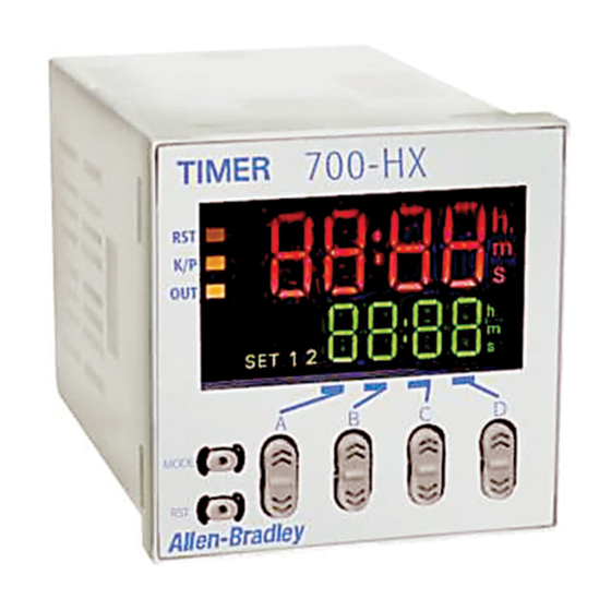
- Page 1 Multifunction Digital Timer 700-HX User Manual...
- Page 2 Since there are many variables and requirements associated with any particular installation, Allen-Bradley does not assume responsibility or liability (to include intellectual property liability) for actual use based upon the examples shown in this publication.
- Page 3 If this product has the CE mark it is approved for installation within the European Communities (EC) European Union and EEA regions. It has been designed and tested to meet Directive Compliance the following directives. EMC Directive This product is tested to meet the Council Directive 89/336/EC Electromagnetic Compatibility (EMC) by applying the following standards, in whole or in part, documented in a technical construction file: •...
- Page 4 Cumulative ON/OFF-duty adjustable repeat cycle toff: Repeat cycle OFF start ton: Repeat cycle ON start Note: In this manual the 700-HX Multifunction Digital Timer will be referred to as “700-HX.” Relays and Timers Selection Guide For Further Information • Publication 700-SG003A-EN-P...
- Page 5 Chapter Product Overview Your 700-HX Multifunction Digital Timer product package includes the Bill of Material following items: Item No. Description Quantity 700-HX Digital Timing Relay — 6-Language Instruction Sheet — Rubber Gasket Basic Product Information Cat. No. Input Voltage Output Modes...
- Page 6 700-HN125 Screw Terminal Tube Base Sockets — Panel or DIN Rail Mounting Open Style Construction 8-pin for use with Bulletin 700-HX timing relays. Order must be for 10 sockets or multiples of 10. No retainer clip required. 199-DR1 DIN Rail Mounting Pack Standard 35 x 7.5 mm DIN Rail, 1 meter long, 10 rails per...
- Page 7 Chapter Product Features Block diagram Output circuit (Basic insulation) Display circuit Internal control Input circuit circuit Key switch circuit (See note.) Power supply circuit Note: Power circuit is not insulated from the input circuit. I/O Functions Inputs Start signal Stops timing in A-2 and A-3 (power ON delay) modes.
- Page 8 Product Features Engineering Data (Reference Values) Reference:A maximum current of 0.15 A can be switched 1,000 at 125V DC (cosφ=1) and a maximum current of 0.1 A can be switched if L/R is 7 ms. In both cases, a life of 100,000 operations can be expected.
- Page 9 Product Features Electrical Ratings Inputs Input signals Start, reset Input method No-voltage input via:NPN transistor or switching of contact Start, reset, gate Minimum input signal width: 1 or 20 ms (selectable) Power reset Minimum power-opening time: 0.5 s (Except for A-3, B-1, and F mode) Control output SPDT contact output: 5 A at 250V AC, resistive load...
- Page 10 Enclosure ratings Panel surface:IP66 and NEMA Type 4 (indoors) Weight Approx. 100 g An attached waterproof packing is necessary to ensure IP66 waterproofing between the 700-HX and installation pan. Nomenclature Operation Key Indicator A Reset Indicator (orange) H Mode Key...
- Page 11 Chapter Functions Settings for Advanced Functions Power ON For details on operations in run mode, refer to 3-9. Note: 1. If the mode is switched to the function setting mode during operation, operation will continue. 2. Changes made to settings in function setting mode are enabled for the first time when the mode is changed to run mode.
- Page 12 (KP-1 to KP-5). The key protect indicator is lit while the key-protect switch is set to ON. Confirm the ON/OFF status of the key-protect switch after the 700-HX is mounted to the panel. Publication 700-UM002A-EN-D - July 2001...
- Page 13 KP-1 Prohibits changing the mode to timer/twin (default timer selection mode or function setting setting) mode. The 700-HX can only be used in run mode. KP-2 Prohibits changing the mode to timer/twin timer selection mode or function setting mode. The 700-HX can only be used in run mode.
- Page 14 Functions Operation in Run Mode When Output Mode Is Not Z Set each digit for the set value using the corresponding keys. Present value Set value When Output Mode Z Is Selected Set each digit for the ON duty ratio using the corresponding keys.
- Page 15 Operation (Twin Timer Switching from Timer to Twin Timer Function) The 700-HX is factory-set for timer operation. To switch to twin timer operation, use the procedure given below. For details, refer to page 3-1. Power ON Timer/twin timer selection mode...
- Page 16 Functions Settings for Advanced Functions Power ON For details on operations in run mode, refer to page 3-4. Note: 1. If the mode is switched to the function setting mode during operation, operation will continue. 2. Changes made to settings in function setting mode are enabled for the first time when the mode is changed to run mode.
- Page 17 (KP-1 to KP-5). The key protect indicator is lit while the key-protect switch is set to ON. Confirm the ON/OFF status of the key-protect switch after the 700-HX is mounted to the panel. Publication 700-UM002A-EN-D - July 2001...
- Page 18 KP-1 Prohibits changing the mode to timer/twin (default timer selection mode or function setting setting) mode. The 700-HX can only be used in run mode. KP-2 Prohibits changing the mode to timer/twin timer selection mode or function setting mode. The 700-HX can only be used in run mode.
- Page 19 The present value is displayed in the main display and the ON set time is displayed in the sub-display. “SET2” lights at the same time. Select whether the 700-HX is used as a timer or a twin timer in timer/twin Operation in Timer/Twin timer selection mode.
- Page 20 2. Setting changes made in timer/twin timer selection mode are enabled when the mode is changed to run mode. If settings are changed, the 700-HX is automatically reset (present value initialized, output turned OFF). The gate input is not included in the 700-HX.
- Page 21 Functions 3-11 Output Mode A-1: Signal ON-Delay 2 (Timer resets when power comes ON.) Power Timing starts when the start signal goes ON, and is reset when the start signal goes OFF. While the start signal is ON, the timer starts when the Start signal power comes ON or when the reset input goes OFF.
- Page 22 3-12 Functions Output mode B: Repeat Cycle 1 (Timer resets when power comes ON.) One-shot Timing starts when the start signal goes ON. Power Output The control output is turned ON when time is up. While the start signal is ON, the timer starts when the Start signal power comes ON or when the reset input goes OFF.
- Page 23 Functions 3-13 Output mode D: Signal OFF-delay (Timer resets when power comes ON.) The control output is ON when the start signal is Power ON (except when the power is OFF or the reset is ON). The timer is reset when the time is up. Start signal Basic Operation Gate...
- Page 24 3-14 Functions Z mode: ON/OFF-duty Adjustable Repeat Cycle Timing starts when the start signal goes ON. Power The status of the control output is reversed when time is up (ON at start). While the start signal is ON, the timer starts when Start signal power comes ON or when the reset input goes OFF.
- Page 25 Chapter Dimensions 700-HX Flush Mounting/ Socket Mounting Note: All units are in millimeters unless otherwise noted. 14.3 48·48 63.7 44.8·44.8 Publication 700-UM002A-EN-D - July 2001...
- Page 26 Dimensions Panel cutouts are as shown below (according to DIN43700). Panel Cutouts 60 min. +0.6 −0 +0.6 −0 60 min. 15 min. Note: 1. The mounting panel thickness should be 1…5 mm. 2. To allow easier operability, it is recommended that adapters are mounted so that the gap between sides with hooks is at least 15 mm.
- Page 27 Internal circuit Signal Reset (–) The power supply and input circuit are not insulated. Terminals one and two of the 700-HX are connected internally. Note: Do not connect unused terminals as relay terminals. Input Circuits Start and reset Input +12 V...
- Page 28 Installation The input of the 700-HX is no-voltage input only. Input Connections No-voltage Inputs (NPN Inputs) Voltage Output Contact input Open Collector (Connection to a voltage out (Connection to NPN open put sensor) collector output sensor) PC or sensor Sensor...
- Page 29 Installation Applicable Two-wire Sensor Leakage current: 1.5 mA max. Switching capacity: 5 mA minimum Residual voltage: 3V DC max. Operating voltage: 10V DC Publication 700-UM002A-EN-D - July 2001...
- Page 30 Diagram Screw Terminal Tube Base Sockets — Panel or DIN Rail Mounting Guarded Terminal Construction (1-3/16) 8-pin for use with Bulletin 700-HX (1-1/32) timing relays. Order must be for 10 sockets or multiples of 10. (2-35/64) Cat. No. 700-HN100 (1-1/2)
- Page 31 Description Specialty Socket 8-pin backwired socket with solder (1-3/8) terminals for use with Bulletin 700-HX timing relays. Order must be for 10 sockets or multiples of (1-1/4) Cat. No. 700-HN108 Frame Adapter For flush or door mounting of all Bulletin 700-HR and -HX timers.
- Page 32 Chapter Precautions Do not use the product in locations subject to flammable ATTENTION or explosive gases. Doing so may result in explosion. The service life of the output relays depends on the ATTENTION switching capacity and switching conditions. Consider the actual application conditions and use the product within the rated load and electrical service life.
- Page 33 Precautions For the power supply of an input device of the 700-HX, use an isolating Power Supplies transformer with the primary and secondary windings mutually isolated and the secondary winding not grounded. 700-HX H5CX Input Input terminal Power supply terminals Circuit Isolation transformer is required.
- Page 34 When the 700-HX is used with power start in F mode (i.e., accumulative operation with output on hold), there will be a timer error (approximately 100 ms each time the 700-HX is turned ON) due to the characteristics of the internal circuitry. Use the 700-HX with signal start if timer accuracy is required.
- Page 35 Precautions It is impossible to provide two independent power switches as shown below regardless of whether or not the timers are different in phase. Input Power Supply Terminal Input Terminal The following displays will appear if an error occurs. Self-diagnostic Function Confirm the error type using the display, and take the appropriate countermeasures.
- Page 36 Tighten the two mounting screws on the Adaptor. Tighten them alternately, a little at a time, so as to keep them at an equal tightness. The 700-HX panel surface is water-resistant (conforming to NEMA 4 and IP66). In order to prevent the internal circuit from water penetration through...
- Page 37 • Store at the specified temperature. If the 700-HX has been stored at a temperature of less than –10°C, allow the 700-HX to stand at room temperature for at least 3 hours before use. • Leaving the 700-HX with outputs ON at a high temperature for a long time may hasten the degradation of internal parts (such as electrolytic capacitors).
- Page 38 Appendix Using the Operation Keys Timer Operation Operation stopped Power ON Can be in operation 3 s min. 1 s min. Timer/twin timer selection mode Run mode Function setting mode 1 s min. Timer (Except for Z mode) 3 s min. Time range Timer/twin timer selection PV/SV...
- Page 39 Appendix-2 The flowcharts on the previous page outline the procedure for all models. For details on specific models, refer to 3-9 (timer operation) or 3-14 (twin timer operation). Fill in your set values in the set value column of the following tables for quick List of Settings reference.
- Page 40 Appendix-3 Run Mode when Output Mode = Z Parameter Parameter Setting range Dafault Unit name value value Present Cycle 0.00 …99.99 0.00 (Time range: --,--s) value, time 0.0 … 999.9 cycle (Time range: ---,-s) time 0 … 9999 (Time range: ----s) 0 0:00 …...
- Page 41 Appendix-4 Settings for Twin Timer Operation Run Mode Parameter name Parameter Setting range Dafault Unit value value 0.00 …99.99 0.00 Present OFF set (Time range: --,--s) value, time 0.0 … 999.9 OFF set (Time range: ---,-s) time 0 … 9999 (Time range: ----s) 0:00 …...
- Page 42 Back Cover Publication 700-UM002A-EN-D - July 2001 © 2001 Rockwell International Corporation. Printed in the U.S.A.
Need help?
Do you have a question about the 700-HX and is the answer not in the manual?
Questions and answers