Table of Contents
Advertisement
Quick Links
Advertisement
Table of Contents

Related Manuals for ZyXEL Communications MetroGigabit MGS3750-28F


Summary of Contents for ZyXEL Communications MetroGigabit MGS3750-28F
- Page 1 M GS3 7 5 0 - 2 8 F Met roGigabit Swit ch Version 1.02 Edit ion 2, 11/ 2016 Quick Start Guide Use r ’s Gu ide D e fa u lt Login D e t a ils I P Addr ess ht t p: / / 192.168.1.1 User Nam e adm in...
- Page 2 IMPORTANT! READ CAREFULLY BEFORE USE. KEEP THIS GUIDE FOR FUTURE REFERENCE. Not e: This guide is a reference for a ser ies of product s. Ther efore som e feat ures or opt ions in t his guide m ay not be available in your product . Screenshot s and graphics in t his book m ay differ slight ly from your product due t o differences in your product firm ware or your com put er operat ing syst em .
-
Page 3: Table Of Contents
Contents Overview Contents Overview Hardware Installation and Connection ......................7 Hardware Overview ..........................10 Logging into the Web Interface .......................15 Overall Web Page Layout ........................16 Basic Settings ............................18 Advanced Application Configurations .....................22 Management ............................61 MGS3750-28F User’s Guide... -
Page 4: Table Of Contents
Table of Contents Table of Contents Contents Overview ..........................3 Table of Contents ..........................4 Chapter 1 Hardware Installation and Connection ....................7 1.1 Installation Scenarios ..........................7 1.2 Desktop Installation Procedure ......................7 1.3 Mounting the Switch on a Rack ......................7 1.3.1 Rack-mounted Installation Requirements ..................7 1.3.2 Attaching the Mounting Brackets to the Switch .................8 1.3.3 Mounting the Switch on a Rack ....................8 Chapter 2... - Page 5 Table of Contents 6.1.2 VLAN Port Settings ........................23 6.1.3 Static VLAN ..........................24 6.2 Static Mac Forwarding ........................25 6.3 Spanning Tree Protocol ........................27 6.3.1 Spanning Tree Configuration ....................28 6.3.2 Compatible/Rapid Spanning Tree Protocol ................29 6.3.3 Multiple Spanning Tree Protocol ....................31 6.4 ERPS Protocol ..........................33 6.4.1 Instance Screen ........................34 6.5 EAPS Protocol ..........................34 6.6 Layer 2 Protocol Tunnel ........................37...
- Page 6 Table of Contents Appendix A Customer Support ......................71 Appendix B Legal Information......................77 MGS3750-28F User’s Guide...
-
Page 7: Hardware Installation And Connection
H A P TE R Hardware Installation and Connection This chapt er shows you how t o inst all and connect t he Swit ch. 1.1 Installation Scenarios The Swit ch can be placed on a deskt op or rack- m ount ed on a st andard EI A rack. Use t he rubber feet in a deskt op inst allat ion and t he bracket s in a rack- m ount ed inst allat ion. -
Page 8: Attaching The Mounting Brackets To The Switch
Chapter 1 Hardware Installation and Connection 1.3.1.1 Precautions • Make sure t he rack will safely support t he com bined weight of all t he equipm ent it cont ains. • Make sure t he posit ion of t he Swit ch does not m ake t he rack unst able or t op- heavy. Take all necessary precaut ions t o anchor t he rack securely before inst alling t he unit . - Page 9 Chapter 1 Hardware Installation and Connection Using a # 2 Philips screwdriver, inst all t he M5 flat head screws t hrough t he m ount ing bracket holes int o t he rack. Repeat st eps t o at t ach t he second m ount ing bracket on t he ot her side of t he rack. MGS3750-28F User’s Guide...
-
Page 10: Hardware Overview
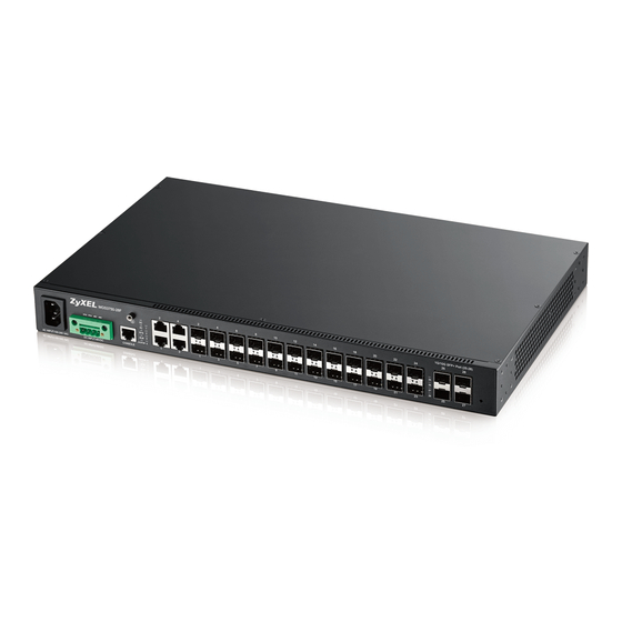
H A P TE R Hardware Overview This chapt er describes t he front panel and rear panel of t he Swit ch and shows you how t o m ake t he hardware connect ions. 2.1 Front Panel The following figure shows t he front panel of t he Swit ch. Figure 3 MGS3750- 28F Front Panel: AC/ DC Model SFP or SFP+ Slot s Console Port... -
Page 11: Transceiver Slots
Chapter 2 Hardware Overview • VT100 • Term inal em ulat ion • 115200 bps • No parit y, 8 dat a bit s, 1 st op bit • No flow cont rol Connect t he m ale 9- pin end of t he console cable t o t he console port of t he Swit ch. Connect t he fem ale end t o a serial port ( COM1, COM2 or ot her COM port ) of your com put er. - Page 12 Chapter 2 Hardware Overview The Swit ch aut om at ically det ect s t he inst alled t ransceiver. Check t he LEDs t o verify t hat it is funct ioning properly. Close t he t ransceiver ’s lat ch ( lat ch st yles vary) . Connect t he fiber opt ic cables t o t he t ransceiver.
-
Page 13: Power Connector
Chapter 2 Hardware Overview 2.1.3 Power Connector Make sure you are using t he correct power source as shown on t he panel and t hat no obj ect s obst ruct t he airflow of t he fans. Use t he following procedures t o connect t he Swit ch t o a power source aft er you have inst alled it . Not e: Check t he power supply requirem ent s on t he panel, and m ake sure you are using an appropriat e power source. -
Page 14: Leds
Chapter 2 Hardware Overview 2.2 LEDs Aft er you connect t he power t o t he Swit ch, view t he LEDs t o ensure proper funct ioning of t he Swit ch and as an aid in t roubleshoot ing. Table 2 LED Descript ions COLOR STATUS... -
Page 15: Logging Into The Web Interface
H A P TE R Logging into the Web Interface 3.1 Launch Browser Ent er ht t p: / / device I P ( default adm inist rat ion I P: 192.168.1.1) . Press Ent er. The login page appears. The default user nam e is " adm in" , and t he default password is " 1234" . Select English or Chinese int erface. -
Page 16: Overall Web Page Layout
H A P TE R Overall Web Page Layout 4.1 Port Status Shown below is an illust rat ion of t he web set up int erface aft er logging in. Figure 10 Port St at us Screen The following t able describes t he labels in t his screen. Table 3 Port St at us Screen LABEL DESCRIPTION... - Page 17 Chapter 4 Overall Web Page Layout Table 3 Port St at us Screen ( cont inued) LABEL DESCRIPTION St at e I f STP ( Spanning Tree Prot ocol) is enabled, t his field displays t he STP st at e of t he port . I f STP is disabled, t his field displays FORW ARD I N G if t he link is up, ot herwise, it displays STOP.
-
Page 18: Basic Settings
H A P TE R Basic Settings 5.1 System Info View basic syst em inform at ion. The I P address and syst em nam e can also be set here. Figure 11 Syst em I nform at ion Screen The following t able describes t he labels in t his screen. -
Page 19: General Application
Chapter 5 Basic Settings Table 4 Syst em I nform at ion Screen ( cont inued) LABEL DESCRIPTION Syst em This field displays t he geographic locat ion of your Swit ch. Locat ion Web page This field displays how m any m inut es a m anagem ent session can be left idle before t he t iim eout ( in session t im es out . -
Page 20: Ip Setup
Chapter 5 Basic Settings 5.3 IP Setup Set syst em I P , gat eway, and subnet m ask here. Figure 13 I P Address Set t ings Screen The following t able describes t he labels in t his screen. Table 6 I P Address Set t ings Screen LABEL DESCRIPTION... - Page 21 Chapter 5 Basic Settings Figure 14 Port Basic Set t ings Screen The following t able describes t he fields in t his screen. Table 7 Port Basic Set t ings Screen LABEL DESCRIPTION Port Num ber " O" m eans connect ed, and " - " m eans not connect ed. Port This is t he port index num ber.
-
Page 22: Advanced Application Configurations
H A P TE R Advanced Application Configurations 6.1 VLAN This chapt er shows you how t o configure port- based VLANs. 6.1.1 VLAN Status Use t his screen t o view and search all VLAN groups. Figure 15 VLAN St at us Screen The following t able describes t he labels in t his screen. -
Page 23: Vlan Port Settings
Chapter 6 Advanced Application Configurations Table 8 VLAN St at us Screen ( cont inued) LABEL DESCRIPTION St at us This field shows how t his VLAN was added t o t he Swit ch. D yn a m ic: using GVRP St a t ic: added as a perm anent ent ry V oice : m anually added as a Voice VLAN M VR: added via m ult icast VLAN regist rat ion... -
Page 24: Static Vlan
Chapter 6 Advanced Application Configurations Table 9 VLAN Port Set t ings Screen LABEL DESCRIPTION Accept able Fram e Specify t he t ype of fram es allowed on a port . Choices are All, Ta g On ly and Un t a g On ly. -
Page 25: Static Mac Forwarding
Chapter 6 Advanced Application Configurations The following t able describes t he labels in t his screen. Table 10 St at ic VLAN Screen LABEL DESCRIPTION Current st at ic Select t he st at ic VLAN group, and m ake configurat ions t o t he group. VLAN Port Num ber This colum n displays t he port s t hat are part icipat ing in a VLAN. - Page 26 Chapter 6 Advanced Application Configurations Figure 18 MAC Address Forwarding Screen The following t able describes t he fields in t his screen. Table 11 MAC Address Forwarding Screen LABEL DESCRIPTION MAC Address Ent er t he MAC address in valid MAC address form at , t hat is, six hexadecim al charact er pairs.
-
Page 27: Spanning Tree Protocol
Chapter 6 Advanced Application Configurations Table 11 MAC Address Forwarding Screen LABEL DESCRIPTION Port This field displays t he port where t he MAC address shown in t he next field will be forwarded. St at us This field displays t he t ype of t he MAC address. Delet e Click D e le t e t o rem ove t he ent ry from t he sum m ary t able. -
Page 28: Spanning Tree Configuration
Chapter 6 Advanced Application Configurations Table 12 Spanning Tree Prot ocol St at us Screen LABEL DESCRIPTION Hello Tim e ( second) This is t he t im e int erval ( in seconds) at which t he root swit ch t ransm it s a configurat ion m essage. -
Page 29: Compatible/Rapid Spanning Tree Protocol
Chapter 6 Advanced Application Configurations Figure 20 Spanning Tree Configurat ion Screen The following t able describes t he fields in t his screen. Table 13 Spanning Tree Configurat ion Screen LABEL DESCRIPTION St at us Click St at us t o go back t o t he Spa n n in g Tr e e Pr ot ocol St a t u s screen. Spanning Tree Mode You can act ivat e one of t he STP m odes on t he Swit ch: STP ( Spanning Tree Prot ocol) , RSTP ( Rapid Spanning Tree Prot ocol) , M STP ( Mult iple Spanning Tree Prot ocol) . - Page 30 Chapter 6 Advanced Application Configurations Figure 21 Com pat ible/ Rapid Spanning Tree Screen The following t able describes t he fields in t his screen. Table 14 Com pat ible/ Rapid Spanning Tree Screen LABEL DESCRIPTION St at us Click St at us t o go back t o t he Spa n n in g Tr e e Pr ot ocol St a t u s screen.
-
Page 31: Multiple Spanning Tree Protocol
Chapter 6 Advanced Application Configurations Table 14 Com pat ible/ Rapid Spanning Tree Screen LABEL DESCRIPTION Port This field displays t he port num ber. Act ive Select t he check box t o enable t he port 's STP funct ion ( default is Act ive) , set port priorit y ( default is 128) and pat h cost ( default is 200000) . - Page 32 Chapter 6 Advanced Application Configurations Table 15 Mult iple Spanning Tree Prot ocol Screen LABEL DESCRIPTION Max Age This is t he m axim um t im e ( in seconds) t he Swit ch can wait wit hout receiving a BPDU before at t em pt ing t o reconfigure.
-
Page 33: Erps Protocol
Chapter 6 Advanced Application Configurations Table 15 Mult iple Spanning Tree Prot ocol Screen LABEL DESCRIPTION Priorit y Configure t he priorit y for each port here. Priorit y decides which port should be disabled when m ore t han one port form s a loop in a swit ch. -
Page 34: Instance Screen
Chapter 6 Advanced Application Configurations Table 16 ERPS Screen LABEL DESCRIPTION Ring Port The four possible port roles are ow ne r, n e igh bor, n e x t - n e igh bor, and com m on . When t he link is norm al, t hen owner and neighbor port s will be in t he discarding m ode while ot her port s will be in t he forwarding m ode. - Page 35 Chapter 6 Advanced Application Configurations Figure 25 EAPS Screen The following t able describes t he fields in t his screen. Table 18 EAPS Screen LABEL DESCRIPTION Act ive Select t his opt ion t o enable EAPS. Hello Tim e This is t he t im e int erval in seconds bet ween BPDU ( Bridge Prot ocol Dat a Unit s) configurat ion m essage generat ions by t he root swit ch.
- Page 36 Chapter 6 Advanced Application Configurations Table 18 EAPS Screen LABEL DESCRIPTION Ring List This field display t he ring I D. " 0" m eans m ast er ring; " 1" m eans sub ring. Delet e Click D e le t e t o rem ove t he select ed ent ry from t he sum m ary t able. Once a row is added t o t he t able but t he ring is not , click on "...
-
Page 37: Layer 2 Protocol Tunnel
Chapter 6 Advanced Application Configurations Table 20 EAPS Screen LABEL DESCRIPTION Click Add t o insert t he ent ry in t he sum m ary t able below and save your changes t o t he Swit ch’s run- t im e m em ory. The Swit ch loses t hese changes if it is t urned off or loses power. -
Page 38: Bandwidth Control
Chapter 6 Advanced Application Configurations Figure 29 Layer 2 Prot ocol Tunnel Screen The following t able describes t he fields in t his screen. Table 22 Layer 2 Prot ocol Tunnel Screen LABEL DESCRIPTION Port This field displays t he port num ber. Use t his row t o m ake t he set t ing t he sam e for all port s. -
Page 39: Broadcast Storm Control
Chapter 6 Advanced Application Configurations Figure 30 Bandwidt h Cont rol Screen The following t able describes t he fields in t his screen. Table 23 Bandwidt h Cont rol Screen LABEL DESCRIPTION Port This field displays t he port num ber. I ngress Rat e Specify t he m axim um bandwidt h allowed in kilobit s per second ( Kbps) for t he incom ing t raffic flow on a port . -
Page 40: Mirroring
Chapter 6 Advanced Application Configurations The following t able describes t he fields in t his screen. Table 24 Broadcast St orm Cont rol Screen LABEL DESCRIPTION Port This field displays t he port num ber. Broadcast ( unit : 64pp Specify how m any broadcast packet s t he port receives per second. -
Page 41: Link Aggregation
Chapter 6 Advanced Application Configurations Table 25 Mirroring Screen LABEL DESCRIPTION Mirrored Select t his opt ion t o m irror t he t raffic on a port . Direct ion Specify t he direct ion of t he t raffic t o m irror by select ing from t he drop- down list box. Choices are Egr e ss ( out going) , I n gr e ss ( incom ing) and Bot h . -
Page 42: Link Aggregation Setting
Chapter 6 Advanced Application Configurations Table 26 Link Aggregat ion St at us Screen LABEL DESCRIPTION Crit eria This shows t he out going t raffic dist ribut ion algorit hm used in t his t runk group. Packet s from t he sam e source and/ or t o t he sam e dest inat ion are sent over t he sam e link wit hin t he t runk. - Page 43 Chapter 6 Advanced Application Configurations Figure 34 Link Aggregat ion Set t ing Screen The following t able describes t he fields in t his screen. Table 27 Link Aggregat ion Set t ing Screen LABEL DESCRIPTION LACP Enable/ Disable aggregat ion group. Port This field displays t he port num ber.
-
Page 44: Link Aggregation Control Protocol
Chapter 6 Advanced Application Configurations 6.10.2 Link Aggregation Control Protocol Use t his screen t o enable Link Aggregat ion Cont rol Prot ocol. Click LACP in t he upper right corner of Lin k Aggr e ga t ion Se t t in g screen. Figure 35 Link Aggregat ion Cont rol Prot ocol Screen The following t able describes t he fields in t his screen. -
Page 45: Port
Chapter 6 Advanced Application Configurations 6.10.4 Port Figure 37 Port Screen The following t able describes t he fields in t his screen. Table 30 Port Screen LABEL DESCRIPTION Port This field displays t he port num ber. Port Priorit y Set t he priorit y of port s in t he aggregat ion group ( priorit y ranges from 1- 65535) , and default is 128. - Page 46 Chapter 6 Advanced Application Configurations Figure 38 Port Securit y Screen The following t able describes t he fields in t his screen. Table 31 Port Securit y Screen LABEL DESCRIPTION Mac Age Tim e Ent er a t im e from 10 t o 1000000 seconds. This is how long all dynam ically learned MAC addresses rem ain in t he MAC address t able before t hey age out ( and m ust be relearned) .
-
Page 47: Classifier
Chapter 6 Advanced Application Configurations Table 31 Port Securit y Screen LABEL DESCRIPTION Max MAC Lim it Set MAC cont rol learning lim it ( 0- 16384) . MAC learning lim it can only be set when Num ber MAC cont rol learning is enabled for t he port . Users Num ber This field displays t he MAC num bers t hat Swit ch has learned. - Page 48 Chapter 6 Advanced Application Configurations Figure 39 Classifier Screen The following t able describes t he fields in t his screen. Table 32 Classifier Screen LABEL DESCRIPTION Act ive Select t his opt ion t o enable t his rule. Nam e Ent er a descript ive nam e for t his rule for ident ifying purposes.
- Page 49 Chapter 6 Advanced Application Configurations Table 32 Classifier Screen LABEL DESCRIPTION MAC Address Select An y t o apply t he rule t o all MAC addresses. To specify a dest inat ion, select M AC/ M a sk t o ent er t he dest inat ion MAC address of t he packet in valid MAC address form at ( six hexadecim al charact er pairs) and t ype t he m ask for t he specified MAC address t o det erm ine which bit s a packet ’s MAC address should m at ch.
-
Page 50: Policy Rule
Chapter 6 Advanced Application Configurations Table 32 Classifier Screen LABEL DESCRIPTION Act ive This field displays Ye s when t he rule is act ivat ed and N o when it is deact ivat ed. Nam e This field displays t he descript ive nam e for t his rule. This is for ident ificat ion purpose only. - Page 51 Chapter 6 Advanced Application Configurations Table 33 Policy Screen LABEL DESCRIPTION Classifier( s) This field displays t he act ive classifier( s) you configure in t he Cla ssifie r screen. Select t he classifier( s) t o which t his policy rule applies. To select m ore t han one classifier, press [ SHI FT] and select t he choices at t he sam e t im e.
-
Page 52: Queuing Method
Chapter 6 Advanced Application Configurations Table 33 Policy Screen LABEL DESCRIPTION Diffserv Select N o ch a n ge t o keep t he TOS and/ or DSCP fields in t he packet s. Select Se t t h e pa ck e t ’s TOS fie ld t o set t he TOS field wit h t he value you configure in t he TOS field. -
Page 53: Multicast
Chapter 6 Advanced Application Configurations Weighted Round Robin Scheduling (WRR) Round Robin Scheduling services queues on a rot at ing basis and is act ivat ed only when a port has m ore t raffic t han it can handle. A queue is a given an am ount of bandwidt h irrespect ive of t he incom ing t raffic on t hat port . -
Page 54: Multicast Setting
Chapter 6 Advanced Application Configurations Figure 42 Mult icast St at us Screen The following t able describes t he fields in t his screen. Table 35 Mult icast St at us Screen LABEL DESCRIPTION Mult icast Set t ing Configure I GMP- snooping funct ion. -
Page 55: Igmp Snooping Deny Vlan
Chapter 6 Advanced Application Configurations The following t able describes t he fields in t his screen. Table 36 Mult icast Set t ing Screen LABEL DESCRIPTION I GMP Snooping Act ive Select Act ive t o enable I GMP Snooping t o forward group m ult icast t raffic only t o port s t hat are m em bers of t hat group. -
Page 56: Igmp Filtering Profile
Chapter 6 Advanced Application Configurations The following t able describes t he fields in t his screen. Table 37 I GMP Snooping Deny VLAN Screen LABEL DESCRIPTION I GMP Snooping I GMP snooping enables a layer- 2 swit ch t o dynam ically learn t he m em bers of I P m ult icast groups. -
Page 57: Cpu Queue Control
Chapter 6 Advanced Application Configurations The following t able describes t he fields in t his screen. Table 38 I GMP Filt ering Profile Screen LABEL DESCRIPTION Profile Set up Add I GMP filt ering profile. Profile I D The profile I D can be bet ween 1- 128. Profile Descript ion You can add descript ions t o a profile in t his field. -
Page 58: Dos Attack Control
Chapter 6 Advanced Application Configurations Figure 46 CPU Queue Cont rol Screen The following t able describes t he fields in t his screen. Table 39 CPU Queue Cont rol Screen LABEL DESCRIPTION cpu queue cont rol queue ( class of This field displays t he t ype of cont rol packet you want t o configure. - Page 59 Chapter 6 Advanced Application Configurations Figure 47 DoS At t ack Cont rol Screen The following t able describes t he fields in t his screen. Table 40 DoS At t ack Cont rol Screen LABEL DESCRIPTION src m ac and dst m ac Cont rol packet s wit h t he sam e source MAC address as t he current MAC address.
- Page 60 Chapter 6 Advanced Application Configurations Table 40 DoS At t ack Cont rol Screen LABEL DESCRIPTION TCP wit h FI N,URG Cont rol TCP packet s wit h FI N, URG, and PSH bit s whose sequence = 0. and PSH bit s,and sequence equal 0 TCP first fragm ent s Cont rol TCP packet s where t he first fragm ent has t he m inim um TCP header lengt h.
-
Page 61: Management
H A P TE R Management 7.1 Maintenance Use t his screen for Swit ch upgrade, rest art , and m aint enance. Figure 48 Managem ent and Maint enance Screen The following t able describes t he labels in t his screen. Table 41 Managem ent and Maint enance Screen LABEL DESCRIPTION... -
Page 62: Restart System
Chapter 7 Management Figure 49 Firm ware Upgrade Screen The following t able describes t he labels in t his screen. Table 42 Firm ware Upgrade Screen LABEL DESCRIPTION Choose File Click Ch oose File t o upload t he Boot Rom file t o t he Swit ch. Reboot Aft er The Swit ch will reboot aft er t he file is uploaded successfully. -
Page 63: Oam Diag
Chapter 7 Management Table 43 Rest art Syst em Screen ( cont inued) LABEL DESCRIPTION Secondary Host When t he Swit ch st art up, it will run t he secondary host soft ware. This num ber is t he soft ware version on t he Swit ch and it will change once you upgrade/ downgrade it . -
Page 64: Snmp
Chapter 7 Management Figure 52 Access Cont rol Screen The following t able describes t he fields in t his screen. Table 45 Access Cont rol Screen LABEL DESCRIPTION SNMP Click Click H e r e t o m ake configurat ions on SNMP . Logins Click Click H e r e t o m ake configurat ions on logins. -
Page 65: User Information
Chapter 7 Management Table 46 SNMP Screen LABEL DESCRIPTION Set Com m unit y Ent er t he Se t Com m u n it y, which is t he password for incom ing Set- request s from t he m anagem ent st at ion. - Page 66 Chapter 7 Management Table 47 User I nform at ion Screen ( cont inued) LABEL DESCRIPTION Securit y Level Select whet her you want t o im plem ent aut hent icat ion and/ or encrypt ion for SNMP com m unicat ion from t his user. Choose: •...
-
Page 67: Logins
Chapter 7 Management 7.2.3 Logins Use t his screen t o creat e users t hat is able t o login t he web configurat or wit h t heir own user nam es and passwords. Also, if user privilege is 0- 1, it ’s N or m a l user; 2- 15 is Adm inist r a t or user. Figure 55 Logins Screen The following t able describes t he fields in t his screen. -
Page 68: Diagnostic
Chapter 7 Management Table 48 Logins Screen LABEL DESCRIPTION Ret ype t o confirm Ret ype your new syst em password for confirm at ion User privilege Type t he privilege level for t his user. if user privilege is 0- 1, it ’s N or m a l user; 2- 15 is Adm inist r a t or user. -
Page 69: Syslog Server Setup
Chapter 7 Management Figure 57 Syslog Set up Screen The following t able describes t he fields in t his screen. Table 50 Syslog Set up Screen LABEL DESCRIPTION Act ive Select t he check box at t he t op t o enable syslog, and deselect t o disable t his funct ion. Logging t ype Select t he "... - Page 70 Chapter 7 Management Table 51 Syslog Server Set up Screen LABEL DESCRIPTION Cancel Click Ca n ce l t o begin configuring t his screen afresh. Clear Click Cle a r t o ret urn t he fields t o t he fact ory default s. I ndex This is t he index num ber of a syslog server ent ry.
- Page 71 PP E N D I X Customer Support I n t he event of problem s t hat cannot be solved by using t his m anual, you should cont act your vendor. I f you cannot cont act your vendor, t hen cont act a ZyXEL office for t he region in which you bought t he device.
- Page 72 Appendix A Customer Support • ht t p: / / www.zyxel.kz Korea • ZyXEL Korea Corp. • ht t p: / / www.zyxel.kr Malaysia • ZyXEL Malaysia Sdn Bhd. • ht t p: / / www.zyxel.com .m y Pakistan • ZyXEL Pakist an ( Pvt .) Lt d. •...
- Page 73 Appendix A Customer Support • ht t p: / / www.zyxel.by Belgium • ZyXEL Com m unicat ions B.V. • ht t p: / / www.zyxel.com / be/ nl/ • ht t p: / / www.zyxel.com / be/ fr/ Bulgaria •...
- Page 74 Appendix A Customer Support Latvia • ZyXEL Lat via • ht t p: / / www.zyxel.com / lv/ lv/ hom epage.sht m l Lithuania • ZyXEL Lit huania • ht t p: / / www.zyxel.com / lt / lt / hom epage.sht m l Netherlands •...
- Page 75 Appendix A Customer Support • ht t p: / / www.zyxel.ch/ Turkey • ZyXEL Turkey A.S. • ht t p: / / www.zyxel.com .t r • ZyXEL Com m unicat ions UK Lt d. • ht t p: / / www.zyxel.co.uk Ukraine •...
- Page 76 Appendix A Customer Support North America • ZyXEL Com m unicat ions, I nc. - Nort h Am erica Headquart ers • ht t p: / / www.zyxel.com / us/ en/ Oceania Australia • ZyXEL Com m unicat ions Corporat ion •...
- Page 77 PP E N D I X Legal Information Copyright Copyright © 2016 by ZyXEL Com m unicat ions Cor porat ion. The cont ent s of t his publicat ion m ay not be reproduced in any part or as a whole, t ranscribed, st ored in a ret rieval syst em , t ranslat ed int o any language, or t ransm it t ed in any form or by any m eans, elect ronic, m echanical, m agnet ic, opt ical, chem ical, phot ocopying, m anual, or ot herwise, wit hout t he prior writ t en perm ission of ZyXEL Com m unicat ions Corporat ion.
- Page 78 Appendix B Legal Information List of National Codes COUNTRY ISO 3166 2 LETTER CODE COUNTRY ISO 3166 2 LETTER CODE Aust ria Liecht enst ein Belgium Lit huania Bulgaria Luxem bourg Croat ia Malt a Cyprus Net herlands Czech Republic Nor way Denm ark Poland...
- Page 79 Appendix B Legal Information • APPAREI L À LASER DE CLASS 1 ( for product s wit h m ini- GBI C slot s or laser product s, such as fiber- opt ic t ransceiver and GPON product s) . •...
- Page 80 Appendix B Legal Information Environmental Product Declaration MGS3750-28F User’s Guide...
- Page 81 Appendix B Legal Information 台灣 警告使用者: • 這是甲類的資訊產品,在居住的環境中使用時,可能會造成射頻干擾,在這種情況下,使用者會被要求採取某些適當的對策。」 安全警告 - 為了您的安全,請先閱讀以下警告及指示 : • 請勿將此產品接近水、火焰或放置在高溫的環境。 • 避免設備接觸 - 任何液體 - 切勿讓設備接觸水、雨水、高濕度、污水腐蝕性的液體或其他水份。 - 灰塵及污物 - 切勿接觸灰塵、污物、沙土、食物或其他不合適的材料。 • 雷雨天氣時,不要安裝,使用或維修此設備。有遭受電擊的風險。 • 切勿重摔或撞擊設備,並勿使用不正確的電源變壓器。 • 若接上不正確的電源變壓器會有爆炸的風險。。 • 請勿隨意更換產品內的電池。 • 如果更換不正確之電池型式,會有爆炸的風險,請依製造商說明書處理使用過之電池。 • 請將廢電池丟棄在適當的電器或電子設備回收處。 • 請勿將設備解體。 • 請勿阻礙設備的散熱孔,空氣對流不足將會造成設備損害。 •...
- Page 82 Appendix B Legal Information purchase, should t he pr oduct have indicat ions of failure due t o fault y w orkm anship and/ or m at erials, ZyXEL will, at it s discretion, repair or replace t he defect ive product s or com ponent s wit hout charge for eit her part s or labor, and t o what ever ext ent it shall deem necessar y t o rest ore t he product or com ponent s t o pr oper operat ing condit ion.
Need help?
Do you have a question about the MetroGigabit MGS3750-28F and is the answer not in the manual?
Questions and answers