Table of Contents
Advertisement
Quick Links
Advertisement
Table of Contents

Related Manuals for Rice Lake Farm Bars


Summary of Contents for Rice Lake Farm Bars
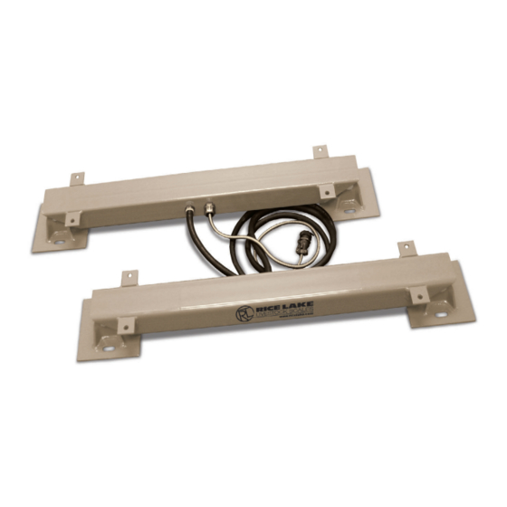
- Page 1 Farm Bars Animal Scale Operation Manual February 9, 2023 PN 127468 Rev C...
- Page 2 All information contained within this publication is, to the best of our knowledge, complete and accurate at the time of publication. Rice Lake Weighing Systems reserves the right to make changes to the technology, features, specifications and design of the equipment without notice.
- Page 3 January 18, 2023 Revision history established; updated calibration instructions Table i. Revision Letter History Technical training seminars are available through Rice Lake Weighing Systems. Course descriptions and dates can be viewed at www.ricelake.com/training or obtained by calling 715-234-9171 and asking for the training department.
-
Page 4: Table Of Contents
8.0 Specifications ............... . . 16 Rice Lake continually offers web-based video training on a growing selection of product-related topics at no cost. -
Page 5: Introduction
Introduction This manual is intended for use by individuals responsible for installing and servicing Farm Bars. Placing a set of Farm Bars beneath any platform or container allows it to function as a weigh scale. Various indicator combinations can be matched to the Farm Bar to meet specialized applications. -
Page 6: Technical Specifications
U Series Farm Bars Technical Specifications 8 ft Interconnecting Cable 4 1/4 in Instrument Connection Mounting Holes Figure 2-1. Farm Bar Dimensions 22.00 in 15.00 in 19.75 in 25.75 in 4.00 in Table 2-1. Farm Bar 2,500U Dimensions 26.00 in 19.00 in... - Page 7 ±0.25% of Reading Compensated Temp. Range 15 to 100°F Operating Temp. Range -25 to 110°F Overload Capacity 150% of Rated Capacity Shipping Weight 48 lb 69 lb 110 lb Table 2-4. Specifications © Rice Lake Weighing Systems ● All Rights Reserved...
-
Page 8: Installation
Immersing the load cells in water can damage the load cells and void the warranty. • Install the Farm Bars on a firm, level surface. The Farm Bars do not have to be installed perfectly level, but a substantial slope decreases accuracy. -
Page 9: Parts List
Figure 4-1. Farm Bar Illustrated Parts IMPORTANT: Specify length in inches (i.e. 55206-3-33), 2500U only comes in 22" lengths. Assembly includes, bearing collar, bearing, snap ring, foam seals and set screws. © Rice Lake Weighing Systems ● All Rights Reserved... - Page 10 U Series Farm Bars Item No. Part No. Description Consult Farm Bar tube, one hole Consult Farm Bar tube, two holes 126864 Label, not Legal for Trade 3.125 x 0.375 blue on white reflective background slitback square corners loadbars 126893...
-
Page 11: Maintenance
All load cells are factory calibrated to reduce installation errors. However, regular recalibration is necessary to compensate for scale drifting. Farm Bars can be calibrated using Rice Lake’s 380 Synergy Series indicator front panel or EDP commands. NOTE: CAL jumper must be removed to perform calibration. -
Page 12: Front Panel Calibration
U Series Farm Bars 5.1.1 Front Panel Calibration To calibrate the indicator using the front panel, do the following. 5.1.1.1 Span Calibration Use the following steps to perform a standard span calibration on a connected scale. 1. Press during power up to access the Setup menu. -
Page 13: Alternative Zero Calibrations
11. If hooks or chains were used to attach the weights, remove all weight, including the hooks and chains, and send the command SC.REZERO#s to remove the zero offset. 12. Send the command KSAVEEXIT to return to weigh mode. © Rice Lake Weighing Systems ● All Rights Reserved... -
Page 14: Troubleshooting
General If having trouble with the Farm Bars, perform the following procedures to diagnose the problem. First, inspect the scale for any physical damage. Take special note of the cable and connectors. Wiggle the cables and connectors while watching the indicator display. - Page 15 Troubleshooting Figure 6-1. Farm Bar System Wiring Diagram Figure 6-2. Farm Bar System Connection © Rice Lake Weighing Systems ● All Rights Reserved...
-
Page 16: Load Cell Replacement
U Series Farm Bars Load Cell Replacement Figure 7-1. System Schematic If load cell replacement is necessary, follow this procedure: 1. Tie string or wire around the end of the cable for the load cell being replaced. This string will be used to feed the new load cell cable through the bar and to the splicing junction. -
Page 17: 8.0 Specifications
Bridge Resistance: 350 ohm Temperature Range: -40 °F to 111 °F (-40 °C to 44 °C) Cable Configuration: 8 ft between bars and 12 ft for the indicator Warranty: Two-year limited © Rice Lake Weighing Systems ● All Rights Reserved... - Page 18 U Series Farm Bars www.RiceLake.com Visit our website...
- Page 20 © Rice Lake Weighing Systems Content subject to change without notice. 230 W. Coleman St. • Rice Lake, WI 54868 • USA U.S. 800-472-6703 • Canada/Mexico 800-321-6703 • International 715-234-9171 • Europe +31 (0)26 472 1319 February 9, 2023 PN 127468 Rev C...
Need help?
Do you have a question about the Farm Bars and is the answer not in the manual?
Questions and answers