Table of Contents
Advertisement
Quick Links
Advertisement
Table of Contents

Related Manuals for KIRLOSKAR IN 40/160 IL


Summary of Contents for KIRLOSKAR IN 40/160 IL
- Page 1 INSTRUCTIONS ON INSTALLATION, OPERATION AND MAINTENANCE MANUAL KIRLOSKAR PUMP TYPE – IN-IL KIRLOSKAR BROTHERS LIMITED REGD. AND HEAD OFFICE: UDYOG BHAVAN, TILAK ROAD, PUNE 411002 (INDIA) IOM/INIL/SEPT19/00 Issue Date: 05/09/2019 Page 1 of 30 Revision:01...
- Page 2 KIRLOSKAR BROTHERS LIMITED REGD. AND HEAD OFFICE UDYOG BHAVAN, TILAK ROAD, PUNE-411002 WARRANTY We warrant that the pump supplied from us is free from defective material and faulty workmanship. This warranty holds good for a period of 12 months from the date of commissioning the equipment or 18 months from the date of dispatch from our factory, whichever is earlier.
-
Page 3: Table Of Contents
Table of contents 1. Introduction Page No Preface Safety Service and support 1.3.1 Ordering spare parts 1.3.2 Pump serial number 1.3.3 Contact Information Inspection of delivered items Lifting Storage 2. General Pump Description Explanation of Designations Applications 2.3.1 Application guidelines 2.3.2 Field of application Construction... - Page 4 Page no 5. Maintenance Routine Inspections Mechanical Seal Noise 6. Cause of failures 7. Technical data Recommended greases Tightening moments Tools 8. Sectional Drawings and Parts-List Cross-Sectional Drawing Parts list-Sectional Drawing Exploded view - Pump unit assembly Exploded view - Hydraulic parts assembly Exploded view - Drive assembly Exploded view - Shaft end assembly 9.
-
Page 5: Introduction
The data published here comply with the most recent information at the time of going to press. However, they may be subject to later modifications. Kirloskar Brothers Limited reserves the right to change the construction and design of the product at any time without being obliged to change earlier deliveries accordingly. - Page 6 Hazard This symbol refers to electrical safety. This symbol is used to introduce safety instructions whose non- observance may lead to damage to the machine and its functions. This symbol refers to magnetic field safety. This symbol refers to restrict person with having heart pacemaker to avoid contact with magnetic components while pump is in running condition or while carrying out maintenance work of pump KBL products are designed for installation in designated areas, which are to be kept...
-
Page 7: Service And Support
Where a conflict exists between the contents herein and the actual equipment supplied, the user must make an engineering judgment, else contact KBL. Kirloskar Brothers Ltd reserves the right to change the construction and design of the products at any time without being obliged to change products already supplied earlier. -
Page 8: Lifting
Lifting: If a pump or a complete pump unit should be lifted, the slings should be fixed as shown in Figure 1. Figure 1. Lifting instruction NOTE: Proper care should be taken to protect pump and/or prime mover and/or paint at contact area of sling or rope at the time of lifting. -
Page 9: Storage
1.6 Storage: In case the pump is not immediately being used, the pump shaft must be rotated manually once in a month to prevent pitting on bearing surfaces. 1.6.1 Temporary Storage for up to six weeks: If the pump unit is not to be used immediately it should be stored carefully in a horizontal/vertical position, in a sheltered, dry location. -
Page 10: General
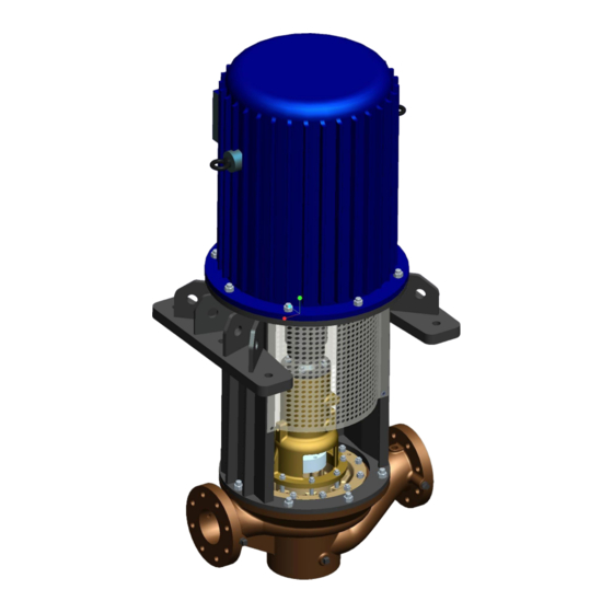
2. General 2.1 Pump Description: Kirloskar IN-IL pump is of vertical execution, back pullout design which enables to remove the rotating unit of pump for inspection and repair without disturbing the pipe connections and motor. Pumps when properly installed and given due care in operation and maintenance should satisfactorily perform for long period of time. -
Page 11: Applications
Material construction Part MOC Code Description → ↓ Pump Casing NiAlBr Cast Iron Impeller NiAlBr Al. Br Cast Iron Pump Shaft SS 431 SS 431 SS 431 SS 316 Casing Ring NiAlBr Cast Iron Impeller Ring NiAlBr Cast Iron Casing Cover NiAlBr Cast Iron Liquid Deflector... -
Page 12: Field Of Application
2.3.2 Field of application: Ballast and Bilge. Air conditioning chilled water. Main fire-fighting. Bilge transfer. Waste water recycling. Portable water supply. Distilling plant feed systems. Main and auxiliary engine cooling. Main boiler feed and condensate. 2.4 Construction: 2.4.1 Pump casing: The casing is of single volute design with suction and discharge connections situated "in- line". -
Page 13: Bearing Assembly
2.5 Re-use: The pump may only be used for other applications after prior consultation with Kirloskar Brothers Ltd or your supplier. Since the lastly pumped medium is not always known, the following instructions should be observed: Flush the pump properly. -
Page 14: Installation
3. Installation 3.1 Safety: These instructions should be read carefully before installing the pump. • This pump is designed for circulation of sea water or other suitable HVAC media. It is not suitable for hazardous, corrosive or flammable liquids. • Pump must not be started until all electrical connections are in place. -
Page 15: After Dismantling
• For spacer coupling no need to remove the motor stool. only remove the spacer coupling. • Remove the hex. nut from casing studs holding the bearing housing (24000) to pump casing (11800). • Slightly pull out the driving unit till impeller (15100) clears the pump casing (11800). •... -
Page 16: Commissioning
• Mount the pair of angular contact ball bearings. Please refer to any standard bearing catalogue for back to back arrangement. Caution: Use arbor press while fitting the bearings. However, it is recommended that bearings should be heated in oil bath at temperature 70-80° C and then fitted. -
Page 17: Direction Of Rotation Of Drive/Driven Shafts
4.2 Direction of rotation of drive/driven shafts: Observe directional arrow. Testing of a unit filled with hydraulic fluid: Switching the unit briefly on and off prevents damage in the case of the wrong direction of rotation. If the direction of rotation is not correct, change connecting wire of motor to match with the rotation of pump. -
Page 18: Maintenance
5. Maintenance 5.1 Routine Inspections: Routine inspections should be made on a regular basis. Inspections made while pump is running should reveal potential failures. A) Inspect motor bearings for any sign of temperature rise. Temperature should not exceed 160°F. Temperature rise may indicate the early stages of bearing problems. B) Listen for any unusual noise. -
Page 19: Cause Of Failures
6. Cause of failures A. Failure: - No Discharge Causes: - • Air leakage in suction line. • Suction lift higher than pump is designed. • Suction pipe block. • Pump not primed. • NPSH available too low. • Incorrect direction of rotation. •... - Page 20 • Casing gasket defective. E. Failure: - Excessive power consumption Causes: - • Speed too high. • System head lower than rating. • Specific gravity of liquid too high. • Mechanical defects. - Shaft bent. - Rotating part running out of concentricity. - Worn out wear ring.
-
Page 21: Technical Data
7. Technical data Recommended greases: Following grades of grease available in the market are suitable. NAME GREASE - SPECIFICATION INDIAN OIL SERVOGEM-2 OR EQUI. CALTEX STARFAX-2 OR EQUI. HINDUSTAN PETROLEUM NATRA-2 or LITHON-2 OR EQUI. INTERNATIONAL GRADE NLGI-2 OR EQUI. Tightening moments: Tightening moments for bolts and nuts Bearing Cover-27000,... - Page 22 22x20 19x18 17x16 15x14 13x12 11x10 32x30 Ring Spanners 27x24 23x21 22x20 19x18 17x16 15x14 13x12 11x10 8 mm Allen key 6 mm 5 mm 4 mm 3 mm Box spanner cap 30 mm Box spanner cap 24 mm Handle for box spanner Internal Circlip Plier (size 200 mm) External Circlip Plier (size 200 mm) Screw Driver (heavy duty 10"...
-
Page 23: Sectional Drawings And Parts-List
8. Sectional Drawings and Parts-List 8.1 Cross-Sectional Drawing: Figure 2. IOM/INIL/SEPT19/00 Issue Date: 05/09/2019 Page 23 of 30 Revision:01... -
Page 24: Parts List-Sectional Drawing
8.2 PARTS LIST-SECTIONAL DRAWING: PART NO. PART DESCRIPTION 10700 PUMP CASING *15100 ENCLOSED IMPELLER *18000 PUMP SHAFT *19000 CASING WEAR RING 22000 CASING COVER *23000 CARTRIDGE MECHANICAL SEAL 23600 WATER DEFLECTOR 24000 BEARING HOUSING *26300 ANGULAR CONTACT BALL BRG. *26400 RADIAL ROLLER BRG. -
Page 25: Exploded View - Pump Unit Assembly
Exploded view – Pump unit assembly: 26400 24000 27100 23600 MOTOR 23000 51600 22000 35000 31100 38800 15100 68200 33000 19000 29000 51100 60000 10700 Figure 3. Exploded view – Pump unit assembly INIL IOM/INIL/SEPT19/00 Issue Date: 05/09/2019 Page 25 of 30 Revision:01... -
Page 26: Exploded View - Hydraulic Parts Assembly
Exploded view – Hydraulic parts assembly: 15100 68200 33000 19000 51100 60000 29000 Figure 4. Exploded view – Hydraulic parts assembly INIL IOM/INIL/SEPT19/00 Issue Date: 05/09/2019 Page 26 of 30 Revision:01... -
Page 27: Exploded View - Drive Assembly
Exploded view – Drive assembly: Figure 5. Exploded view – Drive assembly INIL IOM/INIL/SEPT19/00 Issue Date: 05/09/2019 Page 27 of 30 Revision:01... -
Page 28: Exploded View - Shaft End Assembly
Exploded view – Shaft end assembly: 39800 39700 27000 41500 33600 26300 32100 18000 32000 Figure 6. Exploded view – Shaft end assembly INIL IOM/INIL/SEPT19/00 Issue Date: 05/09/2019 Page 28 of 30 Revision:01... -
Page 29: Dimensional Ga Drawing
Dimensional GA drawing Figure 7: General arrangement drawing *Note – This outline drawing is tentative not for foundation/Structure construction IOM/INIL/SEPT19/00 Issue Date: 05/09/2019 Page 29 of 30 Revision:01... -
Page 30: Outline Dimensions Of Inil Pump
9.1 OUTLINE DIMENSION OF INIL PUMP IOM/INIL/SEPT19/00 Issue Date: 05/09/2019 Page 30 of 30 Revision:01...
Need help?
Do you have a question about the IN 40/160 IL and is the answer not in the manual?
Questions and answers