
Related Manuals for KIRLOSKAR HSC LLC


Summary of Contents for KIRLOSKAR HSC LLC
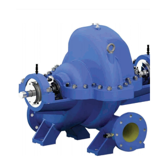
- Page 1 INSTRUCTIONS ON INSTALLATION, OPERATION & MAINTENANCE FOR KIRLOSKAR PUMP TYPE HORIZONTAL SPLIT CASE- “HSC LLC” KIRLOSKAR BROTHERS LIMITED “Yamuna” S.No.98/3 to 7, Baner, Pune 411045...
-
Page 3: Table Of Contents
CONTENTS SR. NO. PAGE NO. GENERAL 2. SAFETY INSTRUCTIONS 3. INSTALLATIONS 4. OPERATION 5. TECHNICAL DATA 6. MAINTENANCE 7. OVERHAULING 8. GENERAL OUTLINE DIMENSIONS 9. CROSS-SECTIONAL DRAWINGS 10. CONTACT INFORMATION Please ensure these instructions are read fully before installation and operation of the pump. -
Page 4: General
1. GENERAL: 1.1 The booklet covers instructions for following types of HSC LLC pumps: Pump Type SCT150/38L SCT200/38L SCT250/38L SCT150/48L SCT200/48L SCT250/30L SCT250/40L UP300/46L UP400/48L UP400/51L UP 400/67L UP 500/68L SCT200/58L SCT250/51L SCT350/39L SCT300/48L SCT350/66L SCT200/58-2L UP300/39L 1.2 These are horizontal split casing type pumps with suction and discharge nozzles and their supporting feet integrally cast in the lower half casing. - Page 5 1.5 Pump Identification: All pumps are designated by serial number, model number, size and type. This information is stamped on an identification plate which is fixed on the pump. 1.6 Nomenclature of the pump. Nomenclature for single stage pump is as given below. SCT 150/38L SCT- Basic pump type 150- Nominal delivery size in mm...
- Page 6 Suction and Discharge is on a common center line in both the horizontal and vertical planes. Impeller – For single stage pumps, impeller is of the enclosed double-suction statically and hydraulically balanced. For two-stage pumps, impellers are of the enclosed single suction type.
-
Page 7: Safety Instructions
Whenever the equipment is operated, maintained or used in any way, the procedures detailed within the Health and Safety Dossier (DHS) and any procedures detailed within these instructions shall be followed. The pump supplied by Kirloskar Brothers Limited (KBL) has been designed with safety in mind, where hazards cannot be eliminated; the risk has been minimized by the use of guards and other design features. - Page 8 2.1.5 Ear defenders should be worn where the specified equipment noise level exceeds locally defined safe levels. Safety glasses or goggles should be worn where working with pressurized systems and hazardous substances. Other personal protection equipment must be worn where local rules apply. DO NOT wear loose or frayed clothing or jewelry, which could catch on the controls...
- Page 9 When lifting the pump or pump set, use lifting equipment having a safe working load rating suitable for the weight specified. Use suitable slings for lifting any pump not provided with lifting points. The use of suitable forklift truck and four chain crane sling equipment is recommended but locally approved equipment rating may be used.
- Page 10 2.6.3 Storage. 2.6.3.1 Temporary Storage up to Six Weeks. If the pump unit is not be used immediately it should be stored carefully in a horizontal position, in a sheltered, dry location. Additional rust preventive should be applied to all unpainted carbon steel or cast-iron parts and should not be removed until final installation.
- Page 11 Fill the bearing housing with recommended grease to ensure that the shaft and bearings remain rust free. 2.6.3.3 Exposed or Extreme Conditions Storage. For exposed storage or extreme variants in atmospheric or environmental conditions, please refer to KBL for special storage instructions to suit the conditions acceptable. IOM/HSC_LLC/FEB/20 Issue Date: 27/02/2020 Page 11 of 90...
-
Page 12: Installations
3. INSTALLATIONS: 3.1 Receiving the Pump. Upon receipt of the pump, a visual check should be made to determine if any shortage or damage occurred during transit or handling. The main items to look for are: a) Broken or cracked equipment, including base, motor or pump feet and flanges. b) Bent shaft. - Page 13 3.3 Location. The pump should be installed as near the suction supply as possible, with the shortest and most direct suction pipe practical. The total dynamic suction lift (static lift plus friction losses in suction line) should not exceed the limits for which the pump was sold. The pump must be primed before starting.
- Page 14 3.4 Foundation. The foundation should be strong enough to reduce vibrations and rigid enough to avoid any twisting or misalignment. The foundation should be poured without interruptions to within 20 to 40 mm of the finished height. The top surface of the foundation should be well scored and glued before the concrete sets.
- Page 15 b) Soak top of concrete foundation thoroughly, then remove surface water. c) Baseplate should be completely filled with grout and, if necessary, drill vent holes to remove trapped air. d) After grout has thoroughly hardened, check the foundation bolts and tighten if necessary. e) Check the alignment after the foundation bolts are tightened.
- Page 16 FACTORS THAT MAY DISTURB ALIGNMENT The unit should be periodically checked for alignment. If the unit does not stay in line after being properly installed, the following are possible reasons: a) Setting, Seasoning of the foundation. b) Pipe strains, distorting or shifting of the machines. c) Wear of the bearings.
- Page 17 IOM/HSC_LLC/FEB/20 Issue Date: 27/02/2020 Page 17 of 90 Revision:00...
- Page 18 3.8 Suction and Discharge Piping. When installing the pump piping, make sure to observe the following precautions: Piping should always move towards the pump. Do not move pump to pipe. This could make final alignment impossible. Both suction and discharge piping should be supported independently and close to pump so that no strain is transmitted to the pump when the flange bolts are tightened.
-
Page 19: Operation
4. OPERATION: 4.1 Before Starting. Before initial starting of the pump, make the following inspection: 4.1.1 The unit baseplate is grouted and bolted to the foundation. 4.1.2 Alignment between pump and motor. 4.1.3 Motor is correctly wired to starting device, check voltage, phase and frequency on motor nameplate with line circuit. - Page 20 The pump should be shut down at once and the trouble corrected if the pump is running at its rated speed and found to have any of the following defects: a) No liquid delivered. b) Not enough liquid delivered. c) Not enough pressure. d) Loss of liquid after starting.
- Page 21 4.5 Operating at reduced capacities:- Do not operate the pump at greatly reduced capacities or with the delivery valve closed. Operating the pump in such condition may be dangerous as the pump will get heated up due to churning of liquid. To guard against possible damages protective devices such as liquid temperature relay, bearing temperature relay, low suction pressure control etc.
- Page 22 IOM/HSC_LLC/FEB/20 Issue Date: 27/02/2020 Page 22 of 90 Revision:00...
-
Page 23: Technical Data
5. TECHNICAL DATA: 5.1 Direction of Rotation. SCT-LLC pumps - Standard direction of rotation is clockwise when viewed from coupling end. UP-LLC pumps - Standard direction of rotation is counter clockwise when viewed from coupling end. Pumps can be supplied with reverse direction of rotation also on request. 5.2 Bearings. - Page 24 5.3 Special Care for Bearings. These instructions do not supersede any information issued by the bearing manufacturers, to whom application should be made for more comprehensive literature by personnel responsible for bearing care, who with it to make a detailed study. Care and maintenance of bearings is a matter of ensuring that they are: a) Correctly lubricated at intervals as laid down in routine maintenance chart.
- Page 25 Operating speed up to Re-greasing Interval 1500 RPM 3000 hours 1800 RPM 2000 hours To recharge the bearings with fresh grease, use a grease gun and feed through the two grease nipples provided. DO NOT APPLY LUBRICANT WHEN PUMP IS RUNNING. After 10,000 hours or two years whichever is earlier remove bearings from pumps, degrease, thoroughly clean, recharge with fresh grease and refit in accordance with reassembly instructions.
- Page 26 5.6 Stuffing Box Details. STUFFING BOX DIMENSIONS FOR SINGLE CARTRIDGE TYPE MECHANICAL SEAL FOR SCT EXTENDED PUMPS 4 TAPPED HOLES (H) OFF CRS BEARING SIDE. IMPELLER SIDE NOTE - ALL DIMENSIONS ARE IN mm. PUMP TYPE H (TAP SIZE) SCT150/38L M12 x 1.75 SCT200/38L, SCT250/38L SCT150/48L, SCT200/48L...
- Page 27 MECHANICAL SEAL- General instructions for operation of the various mechanical sealing arrangements are included below. It is not feasible to include detailed instructions for all mechanical seals in this booklet because of the almost unlimited number of possible combinations and arrangements.
- Page 28 5.9 Minimum Safe Flow. Minimum safe flow = 30% of Best efficiency point discharge and same values are indicated on respective performance curves. (For continuous duty, minimum safe flow values are minimum discharge indicated respectively on performance curves falling on left side of the working range).
- Page 29 5.12 TAPPING DETAILS: Pump Type Priming Flushing Pressure Casing Vent Gauge Drain SCT150/38L, SCT200/38L, 1/4” 1/4” 1/4” 1/2" SCT250/38L, SCT150/48L, SCT200/48L, SCT250/30L, SCT250/40L UP300/46L 3/8” 1-1/4” 1/2” 3/8” 1/2" UP400/48L, UP400/51L, 1/2” 1-1/4” 3/8” 3/8” 1" UP400/67L UP500/68L 3/8” 1-1/4” 3/8”...
- Page 30 5.13 Allowable Forces and Moments on Pump Flanges. Nozzle Forces kg Moments kg-m Size IOM/HSC_LLC/FEB/20 Issue Date: 27/02/2020 Page 30 of 90 Revision:00...
- Page 31 5.14 Suction and Delivery Size. PUMP TYPE SUCTION BORE DELIVERY BORE SCT150/38L SCT200/38L SCT250/38L SCT150/48L SCT200/48L SCT250/30L SCT250/40L UP300/46L UP400/48L UP400/51L UP 400/67L UP 500/68L SCT200/58L SCT250/51L SCT350/39L SCT300/48L SCT350/66L SCT200/58-2L UP300/39L IOM/HSC_LLC/FEB/20 Issue Date: 27/02/2020 Page 31 of 90 Revision:00...
- Page 32 5.15 Water Fill Capacity. PUMP TYPE WATER FILL NOMINAL MAX. CAPACITY SPEED IN RPM ALLOWABLE in LITRES SPEED IN RPM 1450 2080 SCT150/38L 1450 2640 SCT200/38L 1450 2100 SCT250/38L 1450 2100 SCT150/48L 1450 1760 SCT200/48L 1450 2100 SCT250/30L 1450 1800 SCT250/40L 1450 1760...
- Page 33 5.16 Starting Torque. CASE 1- Starting up with open isolating or regulating valve on delivery side. CASE 2- Starting up with closed isolating or regulating valve with opening the valve when nominal speed is attained. CASE 3- Starting up with open isolating or regulating valve but against static delivery head acting on non-return valve.
- Page 34 5.17 Weights and GD Values. Pump Type Approx. value net weight in kg in kg-m 1.27 SCT150/38L 1.96 SCT200/38L 3.14 SCT250/38L 4.92 SCT150/48L 4.66 SCT200/48L 1.02 SCT250/30L 1.93 SCT250/40L 1035 4.91 UP300/46L 1600 28.7 UP400/48L 1650 28.7 UP400/51L 2650 19.2 UP 400/67L 2740 27.02...
-
Page 35: Maintenance
6. MAINTENANCE: Maintenance EHS (Environmental Hazard Safety) Instructions. Following hazards may arise during maintenance work. Fluid Pressure Jet Hazards. Check and ensure that the pump operates at below the maximum Working Pressure specified. Hazardous Materials. Wear a suitable mask or respirator when working with chemical material handling. Hazardous Gases, Mists, Sprays and Leaks. - Page 36 Isolate the equipment before any maintenance work is done. Switch off the mains supply, remove fuses, apply lockouts where applicable and affix suitable isolation warning signs to prevent inadvertent re-connection. In order to avoid the possibility of maintenance personnel inhaling dangerous fumes or vapor’s, it is recommended that maintenance work be carried out away from the pump location by removal of the rotating unit assembly to a suitable maintenance area.
- Page 37 Visually check for leaks. Check for vibration. Hand test bearing housing for any sign of temperature. EVERY WEEK Voltage and current. Check bearing temperature with thermometer. EVERY MONTH EVERY Check grease lubricated bearings for saponification. MONTHS Check shaft or shaft sleeve for scoring. EVERY Check alignment of pump and motor.
-
Page 38: Overhauling
7. OVERHAULING: With normal daily operating spell, the pump will be due for overhaul after about 5000 working hours. This work should be done by skilled personnel. Please refer to the cross- sectional drawing while dismantling and reassembling the pump. Please also refer to the chart given at the end of this booklet. - Page 39 7.1.5 Remove the pump coupling and coupling key. 7.1.6 Remove hex. screws joining each bearing housing with insert and bearing covers. Remove the DE and NDE side bearing housing from bearings and take it off the shaft from DE & NDE side. 7.1.7 Remove bearing lock nut and lock washer from DE side.
- Page 40 7.2 Dismantling Procedure for UP300/46L, UP400/48L, UP400/51L, UP400/67L, UP500/68L, UP300/39L pumps:- 7.2.1 Disengage pump coupling from motor coupling & remove spacer between pump and motor coupling hubs. Drain the pump by removing drain plug and opening air vent valve. Remove hex nuts from studs holding mechanical seal (DE and NDE side). Take mechanical seal back on the shaft.
- Page 41 7.2.8 For UP300/46L, UP400/48L and UP400/51L - Remove DE side bearings along with bearing cover from the shaft by using bearing puller. Remove NDE side bearing in the same manner. 7.2.9 For UP300/39L, UP400/67L and UP500/68L - Remove DE side bearings from the shaft by using bearing puller.
- Page 42 7.3 Dismantling Procedure for SCT250/51L, SCT350/39L, SCT300/48L and SCT350/66L pumps:- 7.3.1 Disengage pump coupling from motor coupling & remove spacer between pump and motor coupling hubs. Drain the pump by removing drain plug and opening air vent valve. Remove hex nuts from studs holding mechanical seal (DE and NDE side). Take mechanical seal back on the shaft.
- Page 43 7.3.7 Remove bearing lock nut and lock washer from DE side. 7.3.8 Remove DE side bearings along with bearing cover from the shaft by using bearing puller. Remove NDE side bearing and bearing cover in the same manner. 7.3.9 Remove V-rings from DE and NDE side. 7.3.10 Slide back DE and NDE side mechanical seal and take off the shaft.
- Page 44 Dismantling Procedure for SCT200/58-2 stage pump:- 7.4.1 Disengage pump coupling from motor coupling & remove spacer between pump and motor coupling hubs. Drain the pump by removing drain plug and opening air vent valve. Remove hex nuts from studs holding mechanical seal (DE and NDE side). Take mechanical seal back on the shaft.
- Page 45 7.4.6 Remove bearing lock nut and lock washer from DE side. 7.4.7 Remove DE side bearings along with bearing cover from the shaft by using bearing puller. Remove NDE side bearing and bearing cover in the same manner. 7.4.8 Remove V-rings from DE and NDE side. 7.4.9 Slide back DE and NDE side mechanical seal and take off the shaft.
- Page 46 Before proceeding for reassembly of rotating unit and pump, following points should be checked: Rotate ball bearings with hand and check if they rotate smoothly. Renew them if they are not rotating freely or if the races are deteriorated. Check shaft for possible run out. Remove the same before assembly. Remove any dust or rust from parts, and clean all parts thoroughly with kerosene or petrol.
- Page 47 7.5 REASSEMBLY procedure for SCT150/38L, SCT200/38L, SCT250/38L, SCT150/48L, SCT200/48L, SCT250/30L, SCT250/40L pumps: 7.5.1 Check ‘O’ rings for cut or flaws, discard if faulty, lubricate and fit in the grooves provided on each insert, casing ring and impeller nut. 7.5.2 Wipe over shaft with clean light oil. 7.5.3 Keep shaft so that coupling end extension is in correct position looking from position of suction and delivery branches.
- Page 48 7.5.6 Apply a hand of light oil on casing rings and place casing rings on the impeller. 7.5.7 Fit ORKOT bush in the insert bore. 7.5.8 Slide DE and NDE side inserts (along with O-ring fitted in the grove on insert outside diameter) over shaft with guide vane at top position.
- Page 49 7.5.18 Cool the bearing to room temperature and coat both sides with grease. 7.5.19 Coat the inside of the NDE side bearing housing with grease and slide into place over bearing. Secure bearing housing to insert with hex. screws. 7.5.20 Fit locating pins for casing and casing ring in their respective holes. 7.5.21 Lift the rotating unit by means of crane.
- Page 50 7.5.29 Rotate the shaft by hand to assure smooth turning and that it is free from rubbing or mechanical friction. 7.5.30 Fit mechanical seal to insert on DE and NDE side maintaining correct pressure between seal faces. 7.5.31 Mount the pump coupling key and fit the pump coupling on the shaft from DE side. 7.5.31 Align motor coupling with pump coupling within 0.05 mm to each other.
- Page 51 7.6 REASSEMBLY Procedure for UP300/46L, UP400/48L, UP400/51L, UP400/67L, UP500/68L, UP300/39L pumps:- 7.6.1 Check ‘O’ rings for cut or flaws, discard if faulty, lubricate and fit in the grooves provided on each insert, casing ring and impeller nut. 7.6.2 Wipe over shaft with clean light oil. 7.6.3 Keep shaft so that coupling end extension is in correct position looking from position of suction and delivery branches.
- Page 52 7.6.7 Fit ORKOT bush in the insert bore. 7.6.8 Slide DE and NDE side inserts (along with O-ring fitted in the grove on insert outside diameter) over shaft with guide vane at top position. 7.6.9 Slide Cartridge type mechanical seal over the shaft from DE and NDE side. 7.6.10 Slide the liquid deflector on the shaft from DE &...
- Page 53 Use hand gloves while handling heated bearings. 7.6.18 Cool the bearing to room temperature and coat both sides with grease. 7.6.19 Coat the inside of the NDE side bearing housing with grease and slide into place over bearing. Secure bearing housing to insert with hex. screws. 7.6.20 Fit locating pins for casing and casing ring in their respective holes.
- Page 54 7.6.28 Mount all the accessories such as grease nipple, flushing connection, etc. 7.6.29 Rotate the shaft by hand to assure smooth turning and that it is free from rubbing or mechanical friction. 7.6.30 Fit mechanical seal to insert on DE and NDE side maintaining correct pressure between seal faces.
- Page 55 7.7 REASSEMBLY Procedure for SCT250/51L, SCT350/39L, SCT300/48L and SCT350/66L pumps:- 7.7.1 Check ‘O’ rings for cut or flaws, discard if faulty, lubricate and fit in the grooves provided on each insert, casing ring and impeller nut. 7.7.2 Wipe over shaft with clean light oil. 7.7.3 Keep shaft so that coupling end extension is in correct position looking from position of suction and delivery branches.
- Page 56 7.7.7 Fit ORKOT bush in the insert bore. 7.7.8 Slide DE and NDE side inserts (along with O-ring fitted in the grove on insert outside diameter) over shaft with guide vane at top position. 7.7.9 Slide Cartridge type mechanical seal over the shaft from DE and NDE side. 7.7.10 Slide the liquid deflector on the shaft from DE &...
- Page 57 7.7.19 Coat the inside of the NDE side bearing housing with grease and slide into place over bearing. Secure bearing housing to insert with hex. screws. 7.7.20 Fit locating pins for casing and casing ring in their respective holes. 7.7.21 Lift the rotating unit by means of crane. Place the rotating unit in the lower half casing such that bearing housings take guide in lower half casing, casing ring shoulders take guide in the groove provided in the lower half casing.
- Page 58 7.7.29 Rotate the shaft by hand to assure smooth turning and that it is free from rubbing or mechanical friction. 7.7.30 Fit mechanical seal to insert on DE and NDE side maintaining correct pressure between seal faces. 7.7.31 Mount the pump coupling key and fit the pump coupling on the shaft from DE side. 7.7.31 Align motor coupling with pump coupling within 0.05 mm to each other.
- Page 59 7.8 REASSEMBLY procedure for SCT200/58-2 stage pump:- 7.8.1 Check ‘O’ rings for cut or flaws, discard if faulty, lubricate and fit in the grooves provided on each insert, casing ring and impeller nut. 7.8.2 Wipe over shaft with clean light oil. 7.8.3 Keep shaft so that coupling end extension is in correct position looking from position of suction and delivery branches.
- Page 60 Check vane direction of both impellers as per pump direction of rotation. Insert 1st stage impeller first from DE side on the shaft. Then fit spacer between impellers in position on the shaft. Check that the “o” ring is fitted in the grooves of spacer. iii) Insert the interstage ring along with interstage bush on the spacer between impellers.
- Page 61 Slide the heated bearings on to the shaft against step at driving end. Ensure that bearings are fitted in BACK-TO-BACK fashion. Allow the bearings to cool up to room temperature. Place locking washer onto shaft & screw bearing lock nut using hook spanner.
- Page 62 7.8.23 Lift upper half casing and place it on lower half casing and engage casing joint nuts loosely. NOTE: When installing casing half upper make sure that the ‘O’ rings are not cut or punched. 7.8.24 Insert locating pins for upper and lower half casing and drive them home. Tighten upper half casing to lower half casing by studs and nuts.
- Page 63 SPARE PARTS A set of ball bearings, a set of casing rings and a set of mechanical seals must always be kept at hand to ensure uninterrupted service from the pump. While ordering for spare parts, always give type, size and serial number of the pump as stamped on the nameplate. 7.4 MATERIAL CONSTRUCTION CODE: The standard code of material of construction is CI fitted with CF8M impeller i.e.
- Page 64 IOM/HSC_LLC/FEB/20 Issue Date: 27/02/2020 Page 64 of 90 Revision:00...
- Page 65 JOINT FLANGE. TIGHTENING TORQUES AND SEQUENCE. Stud and nut used in this main joint flange of SCT pumps should be tightened to the torques stated in Table 1 and in the sequence stated in below Figure. STUD SIZE TIGHTENING TORQUES kg-cm kg-cm 1270...
-
Page 66: General Outline Dimensions
8. GENERAL OUTLINE DIMENSIONS: IOM/HSC_LLC/FEB/20 Issue Date: 27/02/2020 Page 66 of 90 Revision:00... - Page 67 IOM/HSC_LLC/FEB/20 Issue Date: 27/02/2020 Page 67 of 90 Revision:00...
- Page 68 IOM/HSC_LLC/FEB/20 Issue Date: 27/02/2020 Page 68 of 90 Revision:00...
- Page 69 IOM/HSC_LLC/FEB/20 Issue Date: 27/02/2020 Page 69 of 90 Revision:00...
-
Page 70: Cross-Sectional Drawings
9.0 CROSS SECTIONAL DRAWINGS: Cross Sectional Drawing (Single Stage Pump) IOM/HSC_LLC/FEB/20 Issue Date: 27/02/2020 Page 70 of 90 Revision:00... - Page 71 IOM/HSC_LLC/FEB/20 Issue Date: 27/02/2020 Page 71 of 90 Revision:00...
- Page 72 IOM/HSC_LLC/FEB/20 Issue Date: 27/02/2020 Page 72 of 90 Revision:00...
- Page 73 IOM/HSC_LLC/FEB/20 Issue Date: 27/02/2020 Page 73 of 90 Revision:00...
- Page 74 Cross Sectional Drawing (Two Stage Pump) IOM/HSC_LLC/FEB/20 Issue Date: 27/02/2020 Page 74 of 90 Revision:00...
- Page 75 IOM/HSC_LLC/FEB/20 Issue Date: 27/02/2020 Page 75 of 90 Revision:00...
- Page 76 IOM/HSC_LLC/FEB/20 Issue Date: 27/02/2020 Page 76 of 90 Revision:00...
- Page 77 IOM/HSC_LLC/FEB/20 Issue Date: 27/02/2020 Page 77 of 90 Revision:00...
- Page 78 IOM/HSC_LLC/FEB/20 Issue Date: 27/02/2020 Page 78 of 90 Revision:00...
- Page 79 IOM/HSC_LLC/FEB/20 Issue Date: 27/02/2020 Page 79 of 90 Revision:00...
- Page 80 IOM/HSC_LLC/FEB/20 Issue Date: 27/02/2020 Page 80 of 90 Revision:00...
- Page 81 GENERAL INFORMATION & SAFETY INSTRUCTIONS 1. The products supplied by KBL have been designed with safety in mind. Where hazards cannot be eliminated, the risk has been minimized by the use of guards and other design features. Some hazards cannot be guarded against and the instructions below MUST BE COMPLIED WITH for safe operation.
- Page 82 If any tool, procedure, work method and operation technique is not recommended by KIRLOSKAR BROTHERS LIMITED is used or followed, it should be ensured that it is a safe for personnel around and others. It should also be ensured that the product will not be damaged or made unsafe by the operation, lubrication and maintenance or repair procedures you choose.
- Page 83 3. SAFETY INSTRUCTIONS WHILE HANDLING AND STORAGE When lifting the pump, use the lifting points specified on general arrangement drawing, if provided. Use lifting equipment having a safe working load rating suitable for the weight specified. Use suitable slings for lifting pump, which is not provided, with lifting points.
- Page 84 Do not touch any moving or rotating parts. Guards are provided to prevent access to these parts, where they have been removed for maintenance they must be replaced before operating the equipment. Check that pump is primed. Pump should never be run dry as the pumped liquid acts as lubricant for the close running fits surrounding impeller and damage will be incurred.
- Page 85 6. SAFETY INSTRUCTIONS WHILE MAINTENANCE & SERVICING Do not attempt repairs of the pump or its accessories which you do not know. Use proper tools. Before attempting any maintenance on a pump particularly if it has been handling any form of hazardous liquid, it should be ensured that the unit is safe to work on. The pump must be flushed thoroughly with suitable cleaner to purge away any of the product left in the pump components.
- Page 86 Store all oily rags or other flammable material in a protective container in a safe place. Do not weld or flame cut on pipes/tubes that contain flammable fluids. Clean them thoroughly with nonflammable solvent before welding or flame cutting on them. Use solvent/chemical resistant gloves for hand protection.
- Page 87 10. CONTACT INFROMATION: REGIONAL OFFICE AHMEDABAD JAIPUR 11, Mill Officers Colony, B-8, Durga Das Colony, Behind La Gajjar Chambers, Behind Neelkanth Tower, Ashram Road, Ahmedabad 380 009 Bias Godam Circle, Tel: +91-79-26583739, 26580376, Bhawani Singh Road, 26583615, 26583258, 26574500, 26574802 Jaipur - 302001 - Rajasthan Fax: +91-79-26583786 EMAIL ID: ahmedabad@kbl.co.in...
- Page 88 NAGPUR Flat No. 7, Sagar Palace, Laxmi Nagar, MUMBAI 10, Corporate Park, Behind 'Bal Jagat', East High Court Road, Swastik Mills Compound, Nagpur - 440 022 Sion-Trombay Road, Chembur Tel: +91-0712-2234275, 2234276 Mumbai 400 071 Fax: +91-0712-2234276 Tel: +91-022-25289320 to 28 EMAIL ID: nagpur@kbl.co.in Fax: +91-022-25289329 EMAIL ID: mumbai@kbl.co.in...
- Page 89 : general@spppumps.com : Santosh Kulkarni : Steven Keen (General Manager) KIRLOSKAR BROTHERS (THAILAND) LIMITED Kirloskar Brothers (Thailand) Limited 18/8, SPP PUMPS FRANCE 8th Floor, 2, rue du Chateau d'eau, 95450 US Fico Place Building, Sukhumvit 21 (Soi France Asoke), Klong...
- Page 90 Fax: +65 6226 2985 : tamil.s@kirloskarthailand.com : solutions@spppumps.com : Tamil Selvan : Andy Gan (Regional Sales Manager) KIRLOSKAR BROTHERS EUROPE BV Rooswijkweg 7-9, 1951 MD Velsen-Noord, SPP PUMPS Sterling Fluid Systems (SA) (Pty) Ltd The Nederlands 6 B and C Roller Street, Spartan ext 17,...
Need help?
Do you have a question about the HSC LLC and is the answer not in the manual?
Questions and answers