KIRLOSKAR GK Series Instruction On Installation, Operation And Maintenance
Hide thumbs
Also See for GK Series:

Related Manuals for KIRLOSKAR GK Series


Summary of Contents for KIRLOSKAR GK Series
- Page 1 INSTRUCTIONS ON INSTALLATION, OPERATION AND MAINTENANCE FOR KIRLOSKAR PUMP TYPE ‘GK’ KIRLOSKAR BROTHERS LIMITED REGD. AND HEAD OFFICE UDYOG BHAVAN, TILAK ROAD PUNE-411002 IOM/GK/SEP19/00...
- Page 2 This warranty holds good only for the products manufactured by us. KIRLOSKAR BROTHERS LIMITED IOM/GK/SEP19/00...
-
Page 3: Table Of Contents
Table of contents Sr. No. Description Page No. General Safety Instructions Equipment Schedule Operation Maintenance Manual Maintenance EHS instructions General maintenance documents Overhauling 5.3.1 Dismantling 5.3.2 Reassembly Maintenance Tools required Preventive Maintenance 5.5.1 Daily Checks 5.5.2 Periodical Checks 5.5.3 Annual Checks 5.5.4 Mechanical Seal in Pumps Corrective Maintenance... -
Page 4: General
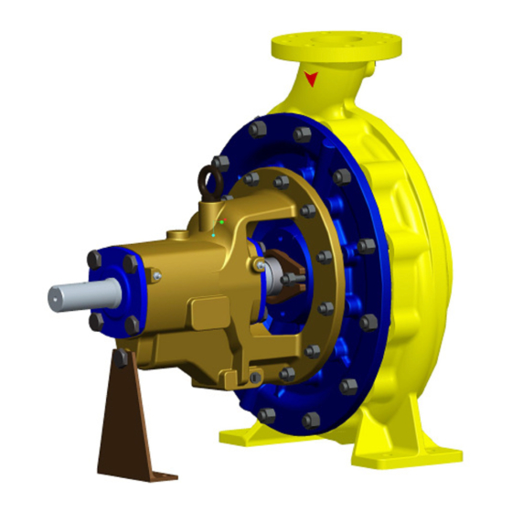
GENERAL ‘KIRLOSKAR’ make GK series pumps are of back pull out design which enables to remove the rotating unit of pump for inspection and repairs without disturbing suction and delivery pipe connections. The booklet covers instructions for installation, operation & maintenance of following models of GK Pumps: UNIT –... -
Page 5: Safety Instructions
Whenever the equipment is operated, maintained or used in any way, the procedures detailed within these instructions shall be followed. pump supplied by Kirloskar Brothers Limited (KBL) has been designed with safety in mind; where hazards cannot be eliminated, the risk has been minimized by the use of guards and other design features. - Page 6 This symbol is used to introduce safety instructions whose CAUTION nonobservance may lead to damage to the machine and its functions. 2.1.2 KBL products are designed for installation in designated areas, which are to be kept clean and free of obstructions that may restrict safe access to the controls and maintenance access points.
- Page 7 Transport Handling and Storage Instructions: 2.6.1 Transport Pumps are dispatched in duly assembled condition. Lubricating oil in the bearing housing is drained prior to dispatch of pump. Pumps are protected against corrosion and packed for transport by normal road, rail and sea carriers.
- Page 8 Storage: 2.6.3 2.6.3.1 Temporary Storage for up to six weeks. If the pump unit is not to be used immediately it should be stored carefully in a horizontal position, in a sheltered, dry location. Additional rust preventive should be applied to all unpainted carbon steel or cast-iron parts and should not be removed until final installation.
-
Page 9: Equipment Schedule
’GENERAL INSTRUCTIONS INSTALLATION, OPERATION MAINTENANCE OF KIRLOSKAR CENTRIFUGAL PUMPS’ which is also printed along this booklet must be followed very carefully. 3.1.2 MOUNTING AND ALIGNMENT A spacer type flexible coupling is used to connect pump shaft to the driver. By... - Page 10 This misalignment is checked by using a straight edge as shown in figure given above. Before commissioning the pump set, please ensure: 3) The pipe connections are flushed and tightened properly. 4) Alignment is proper. 5) Auxiliary piping connections such sealing connections, cooling...
- Page 11 Following tapings are provided on Pump Casing, Suction Cover and bearing housing: IOM/GK/SEP19/00...
-
Page 12: Operation
OPERATION: EQUIPMENT DESCRIPTION: End suction centrifugal pump type GK is from KBL manufactured pump series which dimensionally conforms to ISO 5199 or EN 22858. The mechanical assembly comprises a rigid shaft, supported on deep groove ball bearings with a double shrouded impeller mounted in a removable bearing housing assembly. This is attached to an end suction volute casing fitted with wear rings and back vanes. - Page 13 4) The bearings are not getting abnormally hot. 5) Head and capacity developed by the pump is as specified. 6) Power consumption is within limit. 7) Ensure that there is no mechanical friction in the pipe. 8) Stop the pump immediately, if any defects are detected. Do not start the pump unless the defects are rectified.
-
Page 14: Maintenance Manual
MAINTENANCE MANUAL: MAINTENANCE EHS INSTRUCTIONS: Following hazards may arise during maintenance work. Fluid Pressure Jet Hazards. Check and ensure that the pump operates at below the maximum Working Pressure specified. Before attempting any maintenance on a pump, ensure that the unit is safe to work on. - Page 15 5.3.1.5 In case of the pumps with spacer type flexible couplings, disconnect coupling (pump half and motor half) from the coupling spacer and remove coupling spacer. In case of ordinary flexible couplings, remove the motor from the base. 5.3.1.6 Remove the support foot (25100) hold down bolts. 5.3.1.7 Adjust string or chain tension to support the weight of the back pull out assembly.
- Page 16 5.3.1.15 Removal of stuffing box with gland packing: For this, following steps should be taken: Remove the gland (22900) by taking out bolts used for clamping of the gland. Take out the casing cover (22000) along with gland packing (43000) and lantern ring (22700). 1) Remove the gland packing rings (43000) and lantern ring (22700).
- Page 17 To dismantle shaft seal arrangement: a) Clamped casing cover units – The following pumps have this type of construction. 100/26B 32/13B 65/13A 125/26A 40/13 65/16B 32/13A 50/13 80/16A b) Soft packed pumps – Remove gland nuts and withdraw gland (22300). Unpack stuffing box.
-
Page 18: Reassembly
5.3.1.26 NDE bearing (26000) can be pressed off impeller end of shaft (18000). 5.3.1.27 DE bearing (26000) can be pressed off drive end of shaft (18000), after the careful removal of the shaft circlip ring. During and after dismantling: 1. Wash all old grease from ball bearings and housings with kerosene or white spirit and thoroughly dry bearings. -
Page 19: Maintenance Tools Required
lightly packed with grease, before sliding over shaft end, locating and securing to bearing housing (24000). Maintenance Tools required: No special tools are required for dismantling and reassembling. Toolbox containing a general set of tools such as different size ring spanners, torque wrenches, open ended spanners, light ball peen hammer, wooden mallet, various sizes Allen keys, etc., serves the purpose. -
Page 20: Annual Checks
5.5.2.6 Calibrate the measuring instrument. 5.5.3 Annual Checks: 5.5.3.1 The pump should be overhauled completely to check the clearance and to replace worn-out parts. Clearance between impeller and casing rings, shaft sleeves and throat bush, lantern ring and shaft sleeve, etc., are very important. -
Page 21: Corrective Maintenance
CORRECTIVE MAINTENANCE PUMP TROUBLE When investigating trouble with Kirloskar pumps, always remember that pumps have been tested at the factory and are mechanically correct when sent out. Discounting the possibility of damage during transit, most of the trouble in the field is due to faulty installation. Investigation shows that the majority of troubles with centrifugal pumps result from faulty conditions on the suction side. -
Page 22: Bearing Lubrication
Bearing Lubrication: 6.3.1 Bearings are grease lubricated. Bearings are lubricated during assembly of pump at our factory. The re-greasing should be done after every 2000 hours of running. To recharge the bearing with fresh grease, use a grease gun through the nipples provided. DO NOT APPLY LUBRICANT WHEN PUMP IS RUNNING. -
Page 23: Gaskets, O-Rings & Wear Ring Details
UNIT STUFFING BOX TOTAL POSITION FROM PACKING SIZE LENGTH IMPELLER [mm] PACKING [mm] L=LANT.RING 1180 2+L+3 2+L+2 2+L+2 6.4.4 Gaskets, O-rings and Wear Ring details: A) Gasket Details: As a standard scope pumps are supplied with following gasket and gland packing in materials: Gasket: Ferrolite NAM 37 or equivalent. - Page 24 PART GASKET FOR GASKET FOR GASKET FOR IMPLLER DESCRIPTI CASING & CASING SHAFT SLEEVE COVER 51100 51500 68200 PART 216D X 230D X 1.5TH 20D X 24D X 0.5TH 20D X 28D X 1.5TH GK40/20B 216D X 230D X 1.5TH 20D X 24D X 0.5TH 20D X 28D X 1.5TH GK50/20A...
- Page 25 MODEL SUCTION SIDE DELIVERY SIDE BASIC BASIC DIA. MIN. MAX. DIA. MIN. MAX. GK100/40B 0.443 0.606 0.443 0.606 GK100/26B 0.450 0.622 Back Vane GK125/26A 0.450 0.622 Back Vane GK32/13A 0.430 0.576 Back Vane GK32/13B 0.430 0.576 Back Vane GK40/13 0.336 0.490 Back Vane GK50/13...
-
Page 26: Interchangeability Chart Of Components
6.4.5 INTERCHANGEABILITY CHART OF COMPONENTS IOM/GK/SEP19/00... - Page 27 IOM/GK/SEP19/00...
- Page 28 IOM/GK/SEP19/00...
-
Page 29: Recommended Spare Parts
6.4.6 RECOMMENDED SPARE PARTS: No. / Spares kit Item No. Description No. / Unit 1 year 2 years 3 years 15100 Impeller 18000 Pump Shaft 19000 Suction Wear ring 1 set 1 set 1 set 19100 Delivery Wear ring 1 set 1 set 1 set 22700... - Page 30 CROSS-SECTIONAL DRAWING, PART NO. AND PART DESCRIPTION: IOM/GK/SEP19/00...
- Page 31 IOM/GK/SEP19/00...
- Page 32 IOM/GK/SEP19/00...
- Page 33 IOM/GK/SEP19/00...
- Page 34 IOM/GK/SEP19/00...
- Page 35 IOM/GK/SEP19/00...
-
Page 36: Exploded View
EXPLODED VIEW: IOM/GK/SEP19/00... -
Page 37: General Outline Dimensions
GENERAL OUTLINE DIMENSIONS: IOM/GK/SEP19/00... -
Page 38: Cut Section View
10.0 CUT SECTION VIEW IOM/GK/SEP19/00... - Page 39 GENERAL INFORMATION & SAFETY REQUIREMENTS: 1.1 The products supplied by KBL have been designed with safety in mind. Where hazards cannot be eliminated, the risk has been minimized by the use of guards and other design features. Some hazards cannot be guarded against and the instructions below MUST BE COMPLIED WITH for safe operation.
- Page 40 KIRLOSKAR BROTHERS LIMITED is used, it should be ensured that it is safe for personnel around and others. It should also be ensured that the product will not be damaged or made unsafe by the operation, lubrication and maintenance or repair procedures you choose.
- Page 41 sufficient time for cooling before maintenance. Be cautious and note that other parts of the pump may become hot if a fault is developing. Do not operate water pumps in temperatures below freezing point, without first checking that the pumped fluid is not frozen and the pump is free to rotate. Pumps in these environments should be drained down during inactivity and re-primed before starting.
- Page 42 Dispose of all wastes like gaskets, gland packing, oil batteries, packing material, etc., in accordance with local regulations. Normally this would involve incineration of liquid waste and controlled landfill of polymerized material. Adequacy of suitable crane should be checked before lifting the pump/pump components.
- Page 43 GENERAL INSTRUCTIONS FOR INSTALLATION, OPERATION & MAINTENANCE OF KIRLOSKAR CENTRIFUGAL PUMPS C O R R E C T IN C O R R E C T IOM/GK/SEP19/00...
- Page 44 WARNING The equipment supplied is designed for specific capacity, speed, pressure and temperature. Do not use the equipment beyond the capacities for which it is manufactured. The equipment manufactured is also shop tested for satisfactory performance and if it is operated in excess of the conditions for which it is manufactured, the equipment is subjected to excessive stresses and strains.
- Page 45 LEVELING THE UNIT When the unit is received with the pump and driver mounted on the base plate, it should be placed on the foundation and the coupling halves disconnected. The coupling should not be reconnected until all misalignment operations have been completed. The base plate must be supported evenly on wedges inserted under the four corners so that it will not be distorted or sprung by the uneven distribution of the weight.
- Page 46 The end of the suction pipe must be well submerged to avoid whirlpools and ingress of air but must be kept clear of any deposits of mud, silt, grit, etc. The pipe must be away from any side of the wall by 450 mm. the end of the strainer must be provided with a strainer of sufficient open area.
- Page 47 PRIMING No pumping action occurs unless the pump casing is filled with the liquid. Pump casing and suction pipe must therefore be completely filled with liquid and thus all air removed before the pump is started. Several different priming methods can be used depending on the kind of installation and service involved.
- Page 48 PUMP TROUBLE hen investigating trouble with Kirloskar pumps, always remember that pumps have been tested at the factory and are mechanically correct when sent out. Discounting the possibility of damage during transit, most of the trouble in the field is due to faulty installation.
- Page 49 CAUSE-CHECK POINTS In case of breakdown we recommend the location of the fault by using the following table. BREAKDOWN CHECK POINTS: Pump does not deliver 1 7 8 9 10 11 12 14 15 17 18 19 23 26 52 53 54 Pump delivers at reduced 1 2 3 4 5 6 7 8 9 10 11 12 13 capacity...
- Page 50 CHECK POINTS: 1. Suction pipe, foot valve choked. 2. Nominal diameter of suction line too small. 3. Suction pipe not sufficiently submerged. 4. Too many bends in the suction line. 5. Clearance around suction inlet not sufficient. 6. Shut off valve in the suction line in unfavourable position. 7.
- Page 51 47. Vibration of pipe work. 48. Non-return valve gets caught. 49. Contaminated delivery liquid. 50. Obstruction in delivery line. 51. Delivery flow too great. 52. Pump unsuitable for parallel operation. 53. Type of pump unsuitable. 54. Incorrect choice of pump for existing operating conditions. 55.
Need help?
Do you have a question about the GK Series and is the answer not in the manual?
Questions and answers