
Related Manuals for RCF HL 2240


Summary of Contents for RCF HL 2240
- Page 1 OWNER MANUAL MANUALE D’USO HL 2240 - HORN LOADED SPEAKERS FOR ARRAY SYSTEMS HL 2260 - DIFFUSORI ACUSTICI CARICATI A HL 2290 TROMBA PER “LINE ARRAY” HS 2200...
-
Page 3: Table Of Contents
TABLE OF CONTENTS INDICE ENGLISH SAFETY AND OPERATING PRECAUTIONS DESCRIPTION INSTALLATION CONNECTION SPECIFICATIONS ITALIANO AVVERTENZE PER LA SICUREZZA DESCRIZIONE INSTALLAZIONE COLLEGAMENTO SPECIFICHE TECNICHE... -
Page 4: Safety And Operating Precautions
RCF S.p.A. will not assume any responsibility for the incorrect installation and / or use of this product. SAFETY AND OPERATING PRECAUTIONS 1. - Page 5 11. Hearing loss Exposure to high sound levels can cause permanent hearing loss. The acoustic pressure level that leads to hearing loss is different from person to person and depends on the duration of exposure. To prevent potentially dangerous exposure to high levels of acoustic pressure, anyone who is exposed to these levels should use adequate protection devices.
-
Page 6: Description
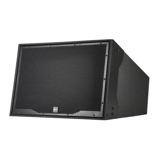
DESIGNED TO GUARANTEE RELIABILITY AND HIGH PERFORMANCE. DESCRIPTION HL 2240, HL 2260 and HL 2290 are horn loaded two-way loudspeakers for array systems for mid distance and long throw applications, both indoors and outdoors. HS 2200 is the matched 18” subwoofer. - Page 8 It is also possible to use two flybars to get a 6-speaker array as shown in the figure below. 33,75° 22,5° The angle between a flybar and its first cabinet is 0°. FLYBAR...
- Page 9 The angle between two adjacent cabinets can be set to 0°, 7.5°, 12.5°, 17.5°, 22.5°. A dedicated acoustic project / study needs to be carried out to find the proper angle. If the angle between two cabinets is set to 0°, it will be necessary to add the additional rear linking plate.
- Page 10 0° 7.5° 12.5° 17.5° 22.5° Fix the front side of two cabinets as shown in the next figure. FIXING EXTERNAL PLATE BRACKET SCREWS...
-
Page 11: Connection
Then, fix the rear bracket, by using the hole corresponding to the proper angle. If the angle between two cabinets is set to 0°, it will be necessary to add the additional rear linking plate. REAR BRACKET EXAMPLE: 0° EXAMPLE: 12.5° CONNECTION WARNING: loudspeaker connections should be only made by qualified and experienced personnel having the technical know-how or sufficient specific instructions (to ensure that... - Page 12 3. Put the clamping ring B into the angled back shell A as shown above. 4. Tighten the nut D to fix the clamping ring to the angled back shell A . HL 2240, HL 2260, HL 2290 On the rear panel, there are 2 inputs linked in parallel (the second can be used as an output for another loudspeaker) for ‘Amphenol’...
- Page 13 HL 2200 - 80 ÷ 120 Hz (HS 2200 subwoofer cutoff) - 600 Hz (HL 2240, HL 2260, HL 2290 woofer / tweeter). GENERIC NOTES ABOUT LOW IMPEDANCE CONNECTIONS - The total loudspeaker impedance must not be lower than the amplifier output impedance.
-
Page 14: Specifications
SPECIFICATIONS HL 2240 HL 2260 HL 2290 HS 2200 SYSTEM FREQUENCY RANGE (–10 dB) 60 Hz ÷ 20 kHz 30 ÷ 200 Hz FREQUENCY RANGE (–3 dB) 80 Hz ÷ 20 kHz 35 ÷ 200 Hz HOR. COVERANGE ANGLE (–6 dB) 40°... -
Page 15: Italiano
INDICE ITALIANO AVVERTENZE PER LA SICUREZZA DESCRIZIONE INSTALLAZIONE COLLEGAMENTO SPECIFICHE TECNICHE... -
Page 16: Avvertenze Per La Sicurezza
Verificare inoltre l’idoneità del supporto (parete, soffitto, struttura ecc.) e dei componenti utilizzati per il fissaggio (tasselli, viti, staffe non fornite da RCF ecc.) che devono garantire la sicurezza dell’impianto / installazione nel tempo, anche considerando, ad esempio, vibrazioni meccaniche normalmente generate da un trasduttore. - Page 17 11. Perdita dell’udito L’esposizione ad elevati livelli sonori può provocare la perdita permanente dell’udito. Il livello di pressione acustica pericolosa per l’udito varia sensibilmente da persona a persona e dipende dalla durata dell’esposizione. Per evitare un’esposizione potenzialmente pericolosa ad elevati livelli di pressione acustica, è necessario che chiunque sia sottoposto a tali livelli utilizzi delle adeguate protezioni;...
-
Page 18: Descrizione
IN MODO DA GARANTIRNE L’AFFIDABILITÀ E PRESTAZIONI ELEVATE. DESCRIZIONE HL 2240, HL 2260 e HL 2290 sono diffusori acustici a due vie da combinare in “line array” per la copertura di medie e lunghe distanze, sia al chiuso sia all’aperto. - Page 20 È possibile, inoltre, utilizzare due “flybar” per ottenere un “array” con 6 diffusori come mostrato nella figura sotto. 33,75° 22,5° L’angolo tra un “flybar” ed il primo diffusore acustico è 0°. FLYBAR...
- Page 21 L’angolo tra due diffusori adiacenti può essere 0°, 7,5°, 12,5°, 17,5° oppure 22,5°. La scelta dell’angolo più opportuno necessita di uno studio acustico dedicato. Se l’angolo tra due diffusori è 0°, è necessario inserire la piastra di fissaggio posteriore addizionale. Entrambe le piastre di fissaggio anteriori (sinistra e destra) hanno dei fori con le indicazioni degli angoli di fissaggio corrispondenti.
- Page 22 0° 7,5° 12,5° 17,5° 22,5° Fissare il lato frontale dei diffusori acustici come mostrato nella figura seguente. PIASTRA DI STAFFA FISSAGGIO ESTERNA VITI M10...
-
Page 23: Collegamento
Successivamente, fissare la staffa posteriore usando il foro corrispondente all’angolo scelto. Se l’angolo tra due diffusori è 0°, è necessario inserire la piastra di fissaggio posteriore addizionale. STAFFA POSTERIORE ESEMPIO: 0° ESEMPIO: 12,5° COLLEGAMENTO ATTENZIONE: per il collegamento del diffusore si raccomanda di rivolgersi a personale qualificato ed addestrato, ossia avente conoscenze tecniche o esperienza o istruzioni specifiche sufficienti per permettergli di realizzare correttamente le connessioni e prevenire i pericoli dell’elettricità. - Page 24 4. Stringere il dado D per fissare l’anello di bloccaggio al guscio posteriore A . HL 2240, HL 2260, HL 2290 Sul retro vi sono 2 ingressi posti in parallelo (il secondo può essere usato come uscita per un altro diffusore acustico) per connettori “Amphenol”.
- Page 25 Frequenze suggerite del crossover: HL 2200 - 80 ÷ 120 Hz (frequenza di taglio per il subwoofer HS 2200) - 600 Hz (woofer / tweeter nei modelli HL 2240, HL 2260, HL 2290). NOTE GENERICHE SUI SISTEMI CON CONNESSIONE A BASSA IMPEDENZA - L’impedenza totale dei diffusori non deve essere inferiore a quella d'uscita...
-
Page 26: Specifiche Tecniche
SPECIFICHE TECNICHE HL 2240 HL 2260 HL 2290 HS 2200 SISTEMA CAMPO DI FREQUENZE (–10 dB) 60 Hz ÷ 20 kHz 30 ÷ 200 Hz CAMPO DI FREQUENZE (–3 dB) 80 Hz ÷ 20 kHz 35 ÷ 200 Hz ANGOLO COPERTURA ORIZ.(–6 dB) 40°... - Page 28 Except possible errors and omissions. RCF S.p.A. reserves the right to make modifications without prior notice. Salvo eventuali errori ed omissioni. RCF S.p.A. si riserva il diritto di apportare modifiche senza preavviso. HEADQUARTERS: RCF S.p.A. Italy tel. +39 0522 274 411 e-mail: info@rcf.it...
Need help?
Do you have a question about the HL 2240 and is the answer not in the manual?
Questions and answers