Table of Contents
Advertisement
Quick Links
Advertisement
Table of Contents

Related Manuals for Casio SF-5580RS


Summary of Contents for Casio SF-5580RS
- Page 1 (without price) SF-5580RS/5780RS (ZX-460) JAN. 1998 SF-5780RS INDEX...
-
Page 2: Table Of Contents
CONTENTS 1. SPECIFICATIONS ....................1 2. GENERAL GUIDE 2-1. Appearances and display indicators ................. 3 2-2. Power Supply ....................... 4 2-3. EL backlight ......................... 5 3. RESET OPERATION ....................6 4. BATTERY REPLACEMENT ..................8 5. DATA COMMUNICATIONS ..................10 6. -
Page 3: Specifications
12-digit arithmetic calculations; independent memory; percentages; square roots; other mixed calcu- lations General: 26-column × 8-line LCD Display element: Memory capacity: SF-5580RS: 128 KB SF-5780RS: 256 KB Main component: Power supply: Main: Two AAA-size alkaline batteries (Type: LR03 (AM4)) Back-up:... - Page 4 Memory Capacity Memory capacity differs according to model. Model Memory SF-5580RS: 128 KB SF-5780RS: 256 KB The following shows the number of items that can be stored in each model. Telephone Directory 8-character name, 10-character Phone ( ) 1 number...
-
Page 5: General Guide
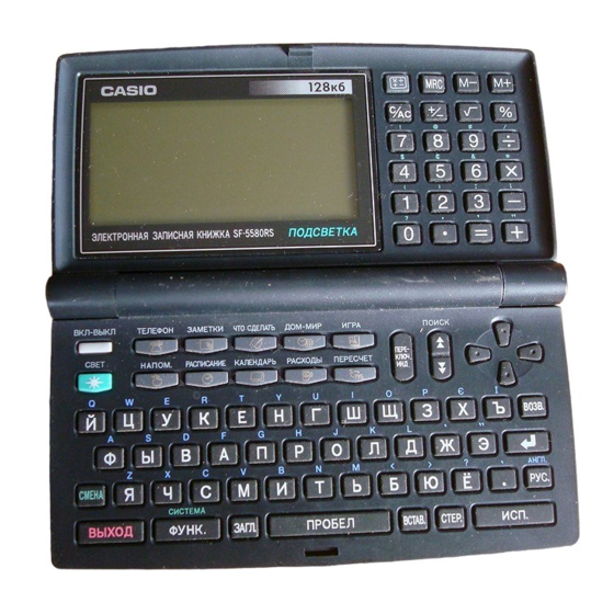
2. GENERAL GUIDE Mode key Memory keys Display 10-key pad Operator keys Mode keys Cursor keys keys keyboard 2-1. Appearances and display indicators When lighting is dim, you can turn on an EL (electro-luminescent) backlight for easier viewing. To turn on the EL backlight There are two ways to turn on the backlight of the display. -
Page 6: Power Supply
Display Indicators 1 Telephone Directory Mode D Upper-case input 2 Memo Mode (ENGLISH/RUSSIAN) 3 To Do Mode key operation 4 Reminder Mode (NEW/EDIT) screen 5 Schedule Keeper Mode G Index display 6 Calendar Mode H Data display 7 Expense Manager Mode I Snooze feature activated 8 Home Time/World Time Mode J Daily alarm on... -
Page 7: El Backlight
Battery Precautions Incorrectly using batteries can cause them to burst or leak, possibly damaging the interior of the Digital Diary. Note the following precautions. • Be sure that the positive (+) side of each battery is facing in the correct directions. •... -
Page 8: Reset Operation
3. RESET OPERATION Use the following procedure to reset the unit to its initial settings. Important! • Do not use a very sharp pencil or other object to press the button. • Be sure to reset the unit before using it for the first time. •... - Page 9 3. Press , select “ ”, and then use the procedure on page 18 of the User’s Manual to set the Home Time. • If you turn power off without setting the Home Time, the “ ” message ap- pears the next time you turn power on. The Digital Diary will not operate properly until you set the Home Time.
-
Page 10: Battery Replacement
4. BATTERY REPLACEMENT To replace the main battery Important! • Do not remove the main batteries from the Digital Diary while the back-up battery is removed. • Be sure to replace both batteries with two new ones. Do not mix an old battery with a new one. •... - Page 11 To replace the back-up battery Important! • Do not remove the back-up battery from the Digital Diary while the main batteries are removed. • Be sure to replace the back-up battery at least once every 5 years. Otherwise, you run the risk of losing data stored in memory.
-
Page 12: Data Communications
5. DATA COMMUNICATIONS Setting Up for Data Communications The following describes what you would do to set up for data communications between two Digital Diary units. To connect to another Digital Diary unit 1. Make sure that the power of both units is turned off. 2. -
Page 13: Operation Check
REMARKS: 1. Executing this check clears the data stored in the Digital Diary. If you do not want them to be cleared, you should store them in another Digital Diary (SF-5580RS/-5780RS) referring to the “5. Data communications” in this manual. - Page 14 7 Wait about 45 to 50 seconds. In the case of SF-5580RS. LCD display ROM TEST ROM OK RAM TEST 1 2 8 K OK In the case of SF-5780RS. LCD display ROM TEST ROM OK RAM TEST 1 2 8 K OK...
- Page 15 D Pressing buttons on the both units, regain to the condition described in the item B. LCD displays on the both units indicates the same display as shown in the item A. E Next, try to transmit data from another unit (B) to a unit (A). F Regain to the condition described in the item B using button.
-
Page 16: Error Messages
7. ERROR MESSAGES Data Error Message The data error message appears whenever the Digital Diary’s internal check discovers a problem with data stored in memory. Appearance of the data error message indicates that you must perform the all-reset procedure to correct the problem. - Page 17 Message Meaning Action The reset procedure has started. See page 6. (ARE YOU USING A NEW UNIT FOR THE FIRST TIME? (Y/N)) T h e r e s e t p r o c e d u r e i s i n See page 6.
-
Page 18: Lsi Pin Function
8. LSI PIN FUNCTION CPU (LC868016A): U1 Pin No. Name I / O Function Power supply for this CPU 2~65 S1~48,C1~16 O Common signals to LCD O Bias power supply to LCD VLCD O Power supply to LCD — Ground for this CPU O Clock for LCD driver LSI(U2, U3:LC868900) O Signal to LCD driver LSI(U2, U3:LC868900)(AC voltage is supplied to LCD by this signal.) -
Page 19: Schematic Diagrams
9. SCHEMATIC DIAGRAMS 9-1. Main PCB ASS’Y (A342054*13)-(1/4) — 17 —... -
Page 20: Main Pcb Ass'y (A342054*13)-(2/4)
9-1. Main PCB ASS’Y (A342054*13)-(2/4) — 18 —... -
Page 21: Main Pcb Ass'y (A342054*13)-(3/4)
9-1. Main PCB ASS’Y (A342054*13)-(3/4) — 19 —... -
Page 22: Main Pcb Ass'y (A342054*13)-(4/4)
9-1. Main PCB ASS’Y (A342054*13)-(4/4) — 20 —... -
Page 23: Keyboard Pcb Ass'y (A342241*1)-(1/3)
9-2. Keyboard PCB ASS’Y (A342241*1)-(1/3) — 21 —... -
Page 24: Keyboard Pcb Ass'y (A342241*1)-(2/3)
9-2. Keyboard PCB ASS’Y (A342241*1)-(2/3) — 22 —... -
Page 25: Keyboard Pcb Ass'y (A342241*1)-(3/3)
9-2. Keyboard PCB ASS’Y (A342241*1)-(3/3) — 23 —... -
Page 26: Disassembly Procedure
10. DISASSEMBLY PROCEDURE 1 Remove two screws then remove the battery cover. 2 Remove three screws. 3 Open the unit and remove two screws behind the display plate. Display plate — 24 —... - Page 27 4 Remove Lower cabinet (keyboard). Lower cabinet (keyboard) 5 Remove Rubber key and knob. Rubber key 6 Desolder the wire connected to the buzzer on the Lower Knob cabinet (keyboard) from key- board PCB ass’y. 7 Remove Lower cabinet (display). Lower cabinet (display) —...
- Page 28 8 Remove screws on PCB shown below then remove PCB ass’y. Main PCB (11 screws) Keyboard PCB (13 screws) 9 Separate upper cabinets. Caution: Heat seal and wires must be placed inside of the hinge in order for the Lower cabinet (keyboard) to fit into place.
-
Page 29: Parts List
Code No. Parts Name Specification Applicable PCB ASSY(A342054) * There are two type of PCB ASSYs in SF-5780RS--A type & B type. 2012 5520 LSI/S-RAM CMO-02-128NC-01 SF-5580RS * U42, U62 2012 5520 LSI/S-RAM CMO-02-128NC-01 SF-5780RS (A-type) * U62 2012 5519 LSI/S-RAM... - Page 30 Item Code No. Parts Name Specification Applicable 3851 2096 PANEL/DISPLAY LEN-01-ZX460-00 SF-5580RS 3851 2097 PANEL/DISPLAY LEN-01-ZX460-01 SF-5780RS 6422 4320 CASE/LOWE DISPLAY HOU-03-ZX876-04 Common 6422 4330 PLATE INL-01-ZX460-00 SF-5580RS 6422 4340 PLATE INL-01-ZX460-01 SF-5780RS 6419 5820 SCREW SCR-01-1740PMTB Common 6419 5840...
-
Page 31: Exploded View
12. EXPLODED VIEW — 29 —... - Page 32 CASIO TECHNO CO.,LTD. Overseas Service Division 8-11-10, Nishi-Shinjuku Shinjuku-ku, Tokyo 160-0023, Japan...
Need help?
Do you have a question about the SF-5580RS and is the answer not in the manual?
Questions and answers