Table of Contents
Advertisement
Quick Links
"RADAR II"
101-050
FAMILY CODE
INSTALLATION AND
USER MANUAL
pag.25
O.M.F.B. S.p.A. Hydraulic Components
We reserve the right to make any changes without notice.
Edition 2003.06 No reproduction, however partial, is permitted.
Via Cave, 7/9 25050 Provaglio d'Iseo (Brescia) Italy Tel.: +39.030.9830611
Fax: +39.030.9839207-208 Internet:www.omfb.it e-mail:contatti@omfb.it
Advertisement
Table of Contents

Summary of Contents for OMFB RADAR II
- Page 1 INSTALLATION AND USER MANUAL pag.25 O.M.F.B. S.p.A. Hydraulic Components We reserve the right to make any changes without notice. Edition 2003.06 No reproduction, however partial, is permitted. Via Cave, 7/9 25050 Provaglio d’Iseo (Brescia) Italy Tel.: +39.030.9830611 Fax: +39.030.9839207-208 Internet:www.omfb.it e-mail:contatti@omfb.it...
-
Page 2: Table Of Contents
................ pag. 44 UNCTIONAL TESTING PROCEDURES 8.1. General comments ..................pag. 44 8.2 Functional testing procedure of the RADAR II receveir unit ......... pag. 45 8.3 REED programming testing procedure .............. pag. 45 8.4 Power outputs testing procedure ..............pag. 46 9. -
Page 3: General Comments
1. RADAR II Midi transmitter (to control 2- and 4-channel systems) 2. RADAR NEW TXF transmitter (to control 2- to 12-channel systems) The OMFB RADAR II system is completely modular, and up to 10 different configurations may be obtained by combining the above components appropriately. -
Page 4: Radar Ii 2-Channel Receveir, Trailer Configuration
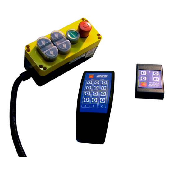
“RADAR II” USER MANUAL 101-050 1.3 RADAR II 2-channel receiver, trailer configuration Emergency Button Start Button Manual control buttons 1.4 RADAR II 4-channel receiver Emergency Button Start Button Manual control buttons channels 1,2 Manual control buttons channels 3,4 pag.28 O.M.F.B. S.p.A. Hydraulic Components We reserve the right to make any changes without notice. -
Page 5: Radar Ii Midi Transmitter
“RADAR II” USER MANUAL 101-050 1.5 RADAR II Midi transmitter To control configurations with 2, 2+2, or 4 channels. Transmitting LED Function buttons EMERGENCY STOP/Emergency push-button pag.29 O.M.F.B. S.p.A. Hydraulic Components We reserve the right to make any changes without notice. -
Page 6: Radar New Txf Transmitter
A, B or C receiver pag.30 O.M.F.B. S.p.A. Hydraulic Components We reserve the right to make any changes without notice. Edition 2003.06 No reproduction, however partial, is permitted. Via Cave, 7/9 25050 Provaglio d’Iseo (Brescia) Italy Tel.: +39.030.9830611 Fax: +39.030.9839207-208 Internet:www.omfb.it e-mail:contatti@omfb.it... -
Page 7: Product Markings And Certification
USER MANUAL 101-050 1.7 Product Markings and certification RADAR II radio remote controls meets the rules set forth in the following harmonised technical standards: • EN 300 220 - 3:2000 for Effective Use of Spectrum; • EN 301 489 - 3:2000 for Electromagnetic Compatibility;... - Page 8 Compliance is shown by product marking: 03 1732 Compliance of RADAR II radio remote controls with the ECE/ONU Reg. No 10 Add. 9 requirements is certified by the Notified Body NSAI4 by releasing the approval number for the product marking: E24 10R-020012.
-
Page 9: Ordering Codes For Radio Remote Controls And Spare Parts
2. O RDERING CODES FOR RADIO REMOTE CONTROLS AND SPARE PARTS 2.1 Ordering codes The “RADAR II” Radio Remote Control may be supplied in the following models: • With RADAR II Midi transmitter: - 10105050050: 2 channel radio remote control... -
Page 10: Technical Specifications
“RADAR II” USER MANUAL 101-050 3. T ECHNICAL SPECIFICATIONS 3.1 RADAR II Midi transmitter apparatus (Regarding the RADAR NEW TXF transmitter, consult the enclosed manual) POWER SUPPLY Battery type 6LR61 9 V ABSORBED CURRENT Max 12-15 mA SPURIOUS EMISSIONS (vs. BASIC) -
Page 11: Radar Ii Receveir Apparatus
4. E LECTRICAL SPECIFICATIONS 4.1 Power supply RADAR II radio remote controls may be powered with a voltage between 10V and 28V in direct current. The power supply line (+12/24V batt and ground) should lead to the receiver directly from the main source (battery or stabilized power source), with cables adequately sized for the load to be carried (cross-section of at least 1 mm^2), also using a safety fuse. -
Page 12: Connecting Devices To The Receiver
MUST be agreed upon by phone with OMFB staff. UP 1 SPEC: For special applications only... -
Page 13: Setting The Output Type (Single/Double-Acting)
The typical device configuration of OMFB radio remote controls is to control systems made up of electric pumps and solenoid valves. The OMFB Radar II receiver is equipped with a series of 4 microswitches, shown in the figure: each microswitch allows the installer to set, for each individual output, the function as double-acting or single-acting, thus it allows the installer to define whether or not the AUX output must be enabled parallel with each individual output. -
Page 14: Output Connectors
• 1 AUX output (see 4.3 for more informa- tion) with a maximum absorption of 8 A. Radar II 2 CH RIM Receiver • 2 outputs to activate electrical devices (such as solenoid valves or relays), with a maximum absorption of 8 A each. The... -
Page 15: Electrical Specifications Of The Admissible Loads
(8 A on one output and 8 A on the AUX output). Where the loads are actually close to this limit, we suggest checking with the OMFB staff to determine whether the type of load may create problems: the information to report includes: type of load (coil, solenoid valve, remote switch, etc.), electrical specifications... -
Page 16: Positioning The Receveir
Do not drill any holes in the box, under penalty of voiding the product warranty. pag.40 O.M.F.B. S.p.A. Hydraulic Components We reserve the right to make any changes without notice. Edition 2003.06 No reproduction, however partial, is permitted. Via Cave, 7/9 25050 Provaglio d’Iseo (Brescia) Italy Tel.: +39.030.9830611 Fax: +39.030.9839207-208 Internet:www.omfb.it e-mail:contatti@omfb.it... -
Page 17: Insertion In Additional Housings
5.5 Installing multiple side-by-side receivers In the RADAR II 2CH+2CH, 6 CH, 8 CH, 10 CH and 12 CH configurations, which involve multiple receivers installed side by side, these must be installed at a minimum distance of 30 mm from one another. -
Page 18: Emergency Stop Engaged By The Receiver
O.M.F.B. S.p.A. Hydraulic Components We reserve the right to make any changes without notice. Edition 2003.06 No reproduction, however partial, is permitted. Via Cave, 7/9 25050 Provaglio d’Iseo (Brescia) Italy Tel.: +39.030.9830611 Fax: +39.030.9839207-208 Internet:www.omfb.it e-mail:contatti@omfb.it... - Page 19 O.M.F.B. S.p.A. Hydraulic Components We reserve the right to make any changes without notice. Edition 2003.06 No reproduction, however partial, is permitted. Via Cave, 7/9 25050 Provaglio d’Iseo (Brescia) Italy Tel.: +39.030.9830611 Fax: +39.030.9839207-208 Internet:www.omfb.it e-mail:contatti@omfb.it...
-
Page 20: Functional Testing Procedures
OMFB staff in identifying problems not caused by OMFB radio remote controls but by other vehicle systems. -
Page 21: Functional Testing Procedure Of The Radar Ii Receveir Unit
“RADAR II” USER MANUAL 101-050 8.2 Functional testing procedure of the RADAR II receiver unit Functional test procedure for RADAR II receiver unit Start Power up the receiver unit Request a return indicating "Possible problems on the power supply line"... -
Page 22: Power Outputs Testing Procedure
• The battery connection is intact and ensures electrical contact; pag.46 O.M.F.B. S.p.A. Hydraulic Components We reserve the right to make any changes without notice. Edition 2003.06 No reproduction, however partial, is permitted. Via Cave, 7/9 25050 Provaglio d’Iseo (Brescia) Italy Tel.: +39.030.9830611 Fax: +39.030.9839207-208 Internet:www.omfb.it e-mail:contatti@omfb.it... - Page 23 IS IT POSSIBLE TO DISABLE THE AUXILIARY SIGNAL WHEN ONE OF THE TWO OR FOUR OUTPUTS IS ACTIVATED? Yes, but this operation may be carried out only by the engineers of OMFB SpA Hydraulic Components, by placing the request directly together with the order, or as a subsequent alteration, referring to “Single-acting”.