Table of Contents
Advertisement
Advertisement
Chapters
Table of Contents

Related Manuals for Rohde & Schwarz FSWP Series


Summary of Contents for Rohde & Schwarz FSWP Series
-
Page 1: User Manual
® R&S FSWP I/Q Analyzer and Spectrum Monitor User Manual (;ÛÈÆ2) 1177585602... - Page 2 ® This manual describes the following R&S FSWP models with firmware version 1.80 or higher: ● ® R&S FSWP8 (1322.8003K08) ● ® R&S FSWP26 (1322.8003K26) ● ® R&S FSWP50 (1322.8003K50) The Spectrum Monitor is integral part of the R&S FSWP and is always available with firmware versions 1.60 and higher.
-
Page 3: Table Of Contents
® Contents R&S FSWP Contents 1 Preface....................5 About this Manual......................5 Documentation Overview..................... 6 Conventions Used in the Documentation..............7 2 Welcome to the I/Q Analyzer Application..........9 Starting the I/Q Analyzer Application................10 Understanding the Display Information..............11 3 Measurement and Result Displays.............14 4 Basics on I/Q Data Acquisition and Processing....... - Page 4 ® Contents R&S FSWP 7 How to Work with I/Q Data..............72 How to Perform Measurements in the I/Q Analyzer Application......72 How to Export and Import I/Q Data................73 8 Remote Commands for the I/Q Analyzer........... 76 Introduction......................... 76 Common Suffixes......................81 Activating I/Q Analyzer Measurements..............81 Performing Measurements..................87 Retrieving Results.......................95...
-
Page 5: Preface
® Preface R&S FSWP About this Manual 1 Preface 1.1 About this Manual This R&S FSWP I/Q Analyzer User Manual provides all the information specific to the application and processing I/Q data. All general instrument functions and settings common to all applications are described in the main R&S FSWP User Manual. The main focus in this manual is on the measurement results and the tasks required to obtain them. -
Page 6: Documentation Overview
® Preface R&S FSWP Documentation Overview 1.2 Documentation Overview This section provides an overview of the R&S FSWP user documentation. Unless specified otherwise, you find most of the documents on the R&S FSWP product page www.rohde-schwarz.com/manual/fswp 1.2.1 Getting Started Manual Introduces the R&S FSWP and describes how to set up and start working with the product. -
Page 7: Conventions Used In The Documentation
® Preface R&S FSWP Conventions Used in the Documentation 1.2.4 Instrument Security Procedures Deals with security issues when working with the R&S FSWP in secure areas. It is available for download on the Internet. 1.2.5 Basic Safety Instructions Contains safety instructions, operating conditions and further important information. The printed document is delivered with the instrument. - Page 8 ® Preface R&S FSWP Conventions Used in the Documentation Convention Description "Graphical user interface ele- All names of graphical user interface elements on the screen, such as ments" dialog boxes, menus, options, buttons, and softkeys are enclosed by quotation marks. [Keys] Key and knob names are enclosed by square brackets.
-
Page 9: Welcome To The I/Q Analyzer Application
® Welcome to the I/Q Analyzer Application R&S FSWP 2 Welcome to the I/Q Analyzer Application The R&S FSWP I/Q Analyzer is a firmware application that adds functionality to per- form I/Q data acquisition and analysis to the R&S FSWP. The R&S FSWP I/Q Analyzer features: ●... -
Page 10: Starting The I/Q Analyzer Application
® Welcome to the I/Q Analyzer Application R&S FSWP Starting the I/Q Analyzer Application Additional information Several application notes discussing I/Q analysis are available from the Rohde & Schwarz website: 1EF85: Converting R&S I/Q data files 1EF92: Wideband Signal Analysis 1MA257: Wideband mm-Wave Signal Generation and Analysis 1EF84: Differential measurements with Spectrum Analyzers and Probes Installation... -
Page 11: Understanding The Display Information
® Welcome to the I/Q Analyzer Application R&S FSWP Understanding the Display Information Only one measurement can be performed at any time, namely the one in the currently active channel. However, in order to perform the configured measurements consecu- tively, a Sequencer function is provided. If activated, the measurements configured in the currently defined channels are per- formed one after the other in the order of the tabs. - Page 12 ® Welcome to the I/Q Analyzer Application R&S FSWP Understanding the Display Information MSRA operating mode In MSRA operating mode, additional tabs and elements are available. A colored back- ground of the screen behind the channel tabs indicates that you are in MSRA operating mode.
- Page 13 ® Welcome to the I/Q Analyzer Application R&S FSWP Understanding the Display Information ● Center frequency ● Number of sweep points ● Range per division (x-axis) ● Span (Spectrum) Status bar information Global instrument settings, the instrument status and any irregularities are indicated in the status bar beneath the diagram.
-
Page 14: Measurement And Result Displays
® Measurement and Result Displays R&S FSWP 3 Measurement and Result Displays Access: "Overview" > "Display Config" Or: [MEAS] > "Display Config" The I/Q Analyzer can capture I/Q data. The I/Q data that was captured by or imported to the R&S FSWP can then be evaluated in various different result displays. Select the result displays using the SmartGrid functions. -
Page 15: Spectrum
® Measurement and Result Displays R&S FSWP Remote command: LAY:ADD:WIND? '1',RIGH,MAGN, see on page 140 LAYout:ADD[:WINDow]? Results: on page 100 TRACe<n>[:DATA]? Spectrum Displays the frequency spectrum of the captured I/Q samples. User Manual 1177.5856.02 ─ 07... -
Page 16: I/Q-Vector
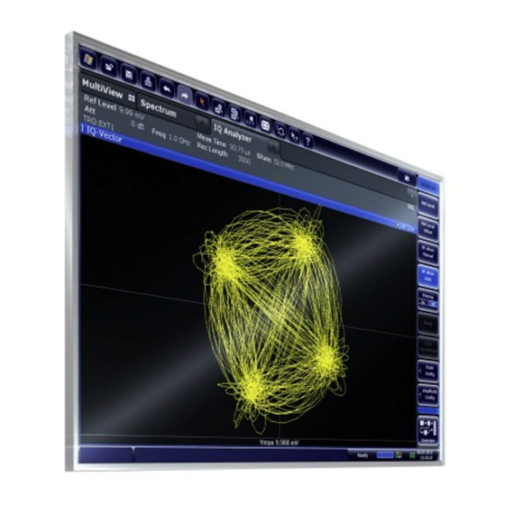
® Measurement and Result Displays R&S FSWP Remote command: LAY:ADD:WIND? '1',RIGH,FREQ, see on page 140 LAYout:ADD[:WINDow]? Results: on page 100 TRACe<n>[:DATA]? I/Q-Vector Displays the captured samples in an I/Q-plot. The samples are connected by a line. Note: For the I/Q vector result display, the number of I/Q samples to record ( "Record Length"... -
Page 17: Marker Table
® Measurement and Result Displays R&S FSWP Remote command: LAY:ADD:WIND? '1',RIGH,RIM, see on page 140 LAYout:ADD[:WINDow]? Results: on page 100 TRACe<n>[:DATA]? Marker Table Displays a table with the current marker values for the active markers. This table is displayed automatically if configured accordingly. Type Shows the marker type and number ("M"... -
Page 18: Marker Peak List
® Measurement and Result Displays R&S FSWP Marker Peak List The marker peak list determines the frequencies and levels of peaks in the spectrum or time domain. How many peaks are displayed can be defined, as well as the sort order. In addition, the detected peaks can be indicated in the diagram. -
Page 19: Basics On I/Q Data Acquisition And Processing
® Basics on I/Q Data Acquisition and Processing R&S FSWP Processing Analog I/Q Data from RF Input 4 Basics on I/Q Data Acquisition and Pro- cessing Some background knowledge on basic terms and principles used when describing I/Q data acquisition on the R&S FSWP in general, and in the I/Q Analyzer application in particular, is provided here for a better understanding of the required configuration set- tings. - Page 20 ® Basics on I/Q Data Acquisition and Processing R&S FSWP Processing Analog I/Q Data from RF Input The A/D converter samples the IF signal at a rate of 200 MHz. The digital signal is down-converted to the complex baseband, lowpass-filtered, and the sample rate is reduced.
- Page 21 ® Basics on I/Q Data Acquisition and Processing R&S FSWP Processing Analog I/Q Data from RF Input 4.1.1 Sample Rate and Maximum Usable I/Q Bandwidth for RF Input Definitions ● Input sample rate (ISR): the sample rate of the useful data provided by the device connected to the input of the R&S FSWP ●...
- Page 22 ® Basics on I/Q Data Acquisition and Processing R&S FSWP Processing Analog I/Q Data from RF Input 4.1.1.2 Relationship Between Sample Rate, Record Length and Usable I/Q Bandwidth Up to the maximum bandwidth, the following rule applies: Usable I/Q bandwidth = 0.8 * Output sample rate Regarding the record length, the following rule applies: Record length = Measurement time * sample rate Maximum record length for RF input...
- Page 23 ® Basics on I/Q Data Acquisition and Processing R&S FSWP Processing Analog I/Q Data from RF Input Usable I/Q bandwidth [MHz] B320 RF input: BW = 0.80*f 10 MHz (without BW option) Output sample rate f [MHz] Figure 4-3: Relationship between maximum usable I/Q bandwidth and output sample rate with and without bandwidth extensions 4.1.1.3 R&S FSWP Without Additional Bandwidth Extension Options...
- Page 24 ® Basics on I/Q Data Acquisition and Processing R&S FSWP Processing Analog I/Q Data from RF Input MSRA operating mode In MSRA operating mode, the MSRA Master is restricted to a sample rate of 600 MHz. Sample rate Maximum I/Q bandwidth 100 Hz to 100 MHz Proportional up to maximum 80 MHz 100 MHz to 10 GHz...
-
Page 25: Basics On Input From I/Q Data Files
® Basics on I/Q Data Acquisition and Processing R&S FSWP Basics on Input from I/Q Data Files Table 4-3: Maximum record length with activated I/Q bandwidth extension option B320 Sample rate Maximum record length 100 Hz to 200 MHz*) 440 Msamples 200 MHz to 468 MHz 470 Msamples * sample rate / 1GHz 468 MHz to 10 GHz... -
Page 26: Receiving And Providing Trigger Signals
® Basics on I/Q Data Acquisition and Processing R&S FSWP Receiving and Providing Trigger Signals Sample iq.tar files If you have the optional R&S FSWP VSA application (R&S FSWP-K70), some sample iq.tar files are provided in the C:/R_S/Instr/user/vsa/DemoSignals directory on the R&S FSWP. Furthermore, you can create your own iq.tar files in the I/Q Analyzer, see Chap- ter 7.2, "How to Export and Import I/Q... -
Page 27: I/Q Data Import And Export
® Basics on I/Q Data Acquisition and Processing R&S FSWP I/Q Data Import and Export 4.4 I/Q Data Import and Export Baseband signals mostly occur as so-called complex baseband signals, i.e. a signal representation that consists of two channels; the in phase (I) and the quadrature (Q) channel. -
Page 28: Basics On Fft
® Basics on I/Q Data Acquisition and Processing R&S FSWP Basics on FFT 4.5 Basics on FFT The I/Q Analyzer measures the power of the signal input over time. To convert the time domain signal to a frequency spectrum, an FFT (Fast Fourier Transformation) is per- formed which converts a vector of input values into a discrete spectrum of frequencies. - Page 29 ® Basics on I/Q Data Acquisition and Processing R&S FSWP Basics on FFT Table 4-4: Characteristics of typical FFT window functions Window type Frequency Magnitude Sidelobe sup- Measurement recommendation resolution resolution pression Rectangular Best Worst Worst No function applied. Separation of two tones with almost equal amplitudes and a small fre- quency distance Blackman-Harris...
- Page 30 ® Basics on I/Q Data Acquisition and Processing R&S FSWP Basics on FFT Figure 4-5: Overlapping FFTs In "Manual" or "Auto" FFT mode, an FFT length of 4096 and a window length of 4096 (or the record length, if shorter) is used to calculate the spectrum. Combining results - trace detector If the record length permits, multiple overlapping windows are calculated and combined to create the final spectrum using the selected trace detector.
- Page 31 ® Basics on I/Q Data Acquisition and Processing R&S FSWP Basics on FFT Record Length Defines the number of I/Q samples to capture. By default, the number of measurement points is used. The record length is calculated as the measurement time multiplied by the sample rate.
- Page 32 ® Basics on I/Q Data Acquisition and Processing R&S FSWP Basics on FFT 4.5.4 Frequency Resolution of FFT Results - RBW The resolution bandwidth defines the minimum frequency separation at which the individual components of a spectrum can be distinguished. Small values result in high precision, as the distance between two distinguishable frequencies is small.
- Page 33 ® Basics on I/Q Data Acquisition and Processing R&S FSWP Basics on FFT Window Length is adapted to comply with Equation 4-1. Since only window lengths with integer values can be employed, the Sample Rate is adapted, if neces- sary, to obtain an integer window length value. If the record length is larger than the window length, multiple windows are combined;...
-
Page 34: I/Q Analyzer In Msra Operating Mode
® Basics on I/Q Data Acquisition and Processing R&S FSWP I/Q Analyzer in MSRA Operating Mode 4.6 I/Q Analyzer in MSRA Operating Mode The I/Q Analyzer can also be used in MSRA operating mode. The MSRA Master chan- nel is implemented as an I/Q Analyzer application. Only this channel captures data in MSRA mode. -
Page 35: Measurements In The Time And Frequency Domain
® Basics on I/Q Data Acquisition and Processing R&S FSWP Measurements in the Time and Frequency Domain For details on the MSRA operating mode see the R&S FSWP MSRA User Manual. 4.7 Measurements in the Time and Frequency Domain The I/Q Analyzer slave application (not Master) in multistandard mode can also per- form measurements on the captured I/Q data in the time and frequency domain. -
Page 36: Configuration
® Configuration R&S FSWP Configuration Overview 5 Configuration The I/Q Analyzer is a special application on the R&S FSWP, which you activate using the [MODE] key on the front panel. When you switch to an I/Q Analyzer measurement channel the first time, a set of parameters is passed on from the currently active application. - Page 37 ® Configuration R&S FSWP Configuration Overview In addition to the main measurement settings, the "Overview" provides quick access to the main settings dialog boxes. The individual configuration steps are displayed in the order of the data flow. Thus, you can easily configure an entire measurement channel from input over processing to output and analysis by stepping through the dialog boxes as indicated in the "Overview".
-
Page 38: Import/Export Functions
® Configuration R&S FSWP Import/Export Functions Select a setting in the channel bar (at the top of the measurement channel tab) to change a specific setting. For step-by-step instructions on configuring I/Q Analyzer measurements, see Chap- ter 7.1, "How to Perform Measurements in the I/Q Analyzer Application", on page 72. - Page 39 ® Configuration R&S FSWP Import/Export Functions I/Q data can only be imported and exported in applications that process I/Q data, such as the I/Q analyzer or other optional applications. See the corresponding user manuals for those applications for details. These functions are only available if no measurement is running. In particular, if Continuous Sweep / Run Cont is active, the import/export functions are...
- Page 40 ® Configuration R&S FSWP Import/Export Functions Note: Secure user mode. In secure user mode, settings that are stored on the instrument are stored to volatile memory, which is restricted to 256 MB. Thus, a "memory limit reached" error can occur although the hard disk indicates that storage space is still available.
-
Page 41: Configuring Data Inputs And Outputs
® Configuration R&S FSWP Configuring Data Inputs and Outputs It is not available in the Spectrum application, only in applications that process I/Q data, such as the I/Q Analyzer or optional applications. For details, see the description in the R&S FSWP I/Q Analyzer User Manual ("Import- ing and Exporting I/Q Data"). - Page 42 ® Configuration R&S FSWP Configuring Data Inputs and Outputs Attenuator", on page 113 and Chapter 8.6.5, "Configuring the Preamplifier", on page 114. Radio Frequency State ....................42 Input Coupling ......................42 Impedance ........................42 High Pass Filter 1 to 3 GHz ..................43 YIG-Preselector ......................43...
- Page 43 ® Configuration R&S FSWP Configuring Data Inputs and Outputs High Pass Filter 1 to 3 GHz Activates an additional internal high-pass filter for RF input signals from 1 GHz to 3 GHz. This filter is used to remove the harmonics of the analyzer to measure the har- monics for a DUT, for example.
- Page 44 ® Configuration R&S FSWP Configuring Data Inputs and Outputs 5.3.1.4 Probes Access: "Overview" > "Input" > "Probes" The functionality to use probes (via the RF input) is the same as in the optional spec- trum application. For a comprehensive description, refer to the user manual of the optional R&S FSWP spectrum application.
- Page 45 ® Configuration R&S FSWP Configuring Data Inputs and Outputs Note: Even when the file input is disabled, the input file remains selected and can be enabled again quickly by changing the state. Remote command: on page 108 INPut<ip>:SELect Select I/Q data file Opens a file selection dialog box to select an input file that contains I/Q data.
- Page 46 ® Configuration R&S FSWP Configuring Data Inputs and Outputs In this case, you can first connect an external noise source (whose noise power level is known in advance) to the R&S FSWP and measure the total noise power. From this value you can determine the noise power of the R&S FSWP.
-
Page 47: Configuring The Amplitude
® Configuration R&S FSWP Configuring the Amplitude Level ← Output Type ← Trigger 1/2 Defines whether a high (1) or low (0) constant signal is sent to the trigger output con- nector. The trigger pulse level is always opposite to the constant signal level defined here. For example, for "Level = High", a constant high signal is output to the connector until you select the Send Trigger... - Page 48 ® Configuration R&S FSWP Configuring the Amplitude The electronic attenuator and its settings are not supported by the R&S FSWP. Functions to configure amplitude characteristics described elsewhere: ● " Input Coupling " on page 42 ● " Impedance " on page 42 ●...
- Page 49 ® Configuration R&S FSWP Configuring the Amplitude Shifting the Display ( Offset ) ← Reference Level Defines an arithmetic level offset. This offset is added to the measured level. In some result displays, the scaling of the y-axis is changed accordingly. Define an offset if the signal is attenuated or amplified before it is fed into the R&S FSWP so the application shows correct power results.
- Page 50 ® Configuration R&S FSWP Configuring the Amplitude Attenuation Mode / Value The RF attenuation can be set automatically as a function of the selected reference level (Auto mode). This ensures that no overload occurs at the RF Input connector for the current reference level.
- Page 51 ® Configuration R&S FSWP Configuring the Amplitude The inherent noise of the instrument depends on the selected center frequency, resolu- tion bandwidth and level setting. Therefore, the correction function is disabled when- ever one of these parameters is changed. A disable message is displayed on the screen.
-
Page 52: Configuring Frequency Characteristics
® Configuration R&S FSWP Configuring Frequency Characteristics Auto Scale Once Automatically determines the optimal range and reference level position to be dis- played for the current measurement settings. The display is only set once; it is not adapted further if the measurement settings are changed again. - Page 53 ® Configuration R&S FSWP Configuring Frequency Characteristics The remote commands required to configure the frequency are described in Chap- ter 8.6.7, "Configuring the Frequency", on page 118. Center Frequency ......................53 Center Frequency Stepsize ..................53 Frequency Offset ......................53 Center Frequency Defines the center frequency of the signal in Hertz.
-
Page 54: Configuring Triggered Measurements
® Configuration R&S FSWP Configuring Triggered Measurements Remote command: on page 119 [SENSe:]FREQuency:OFFSet 5.6 Configuring Triggered Measurements Access (trigger source): "Overview" > "Trigger / Gate" > "Trigger Source" Access (trigger connectors): "Overview" > "Trigger / Gate" > "Trigger In / Out" Trigger settings determine when the input signal is measured. - Page 55 ® Configuration R&S FSWP Configuring Triggered Measurements Drop-Out Time ......................57 Trigger Holdoff ......................57 Slope ..........................57 Trigger Source Selects the trigger source. If a trigger source other than "Free Run" is set, "TRG" is dis- played in the channel bar and the trigger source is indicated. Remote command: on page 123 TRIGger[:SEQuence]:SOURce...
- Page 56 ® Configuration R&S FSWP Configuring Triggered Measurements The available trigger levels depend on the RF attenuation and preamplification. A refer- ence level offset, if defined, is also considered. For details on available trigger levels and trigger bandwidths, see the data sheet. Remote command: TRIG:SOUR IFP, see on page 123...
- Page 57 ® Configuration R&S FSWP Configuring Triggered Measurements Repetition Interval Defines the repetition interval for a time trigger. The shortest interval is 2 ms. The repetition interval should be set to the exact pulse period, burst length, frame length or other repetitive signal characteristic. Remote command: on page 124 TRIGger[:SEQuence]:TIME:RINTerval...
-
Page 58: Data Acquisition And Bandwidth Settings
® Configuration R&S FSWP Data Acquisition and Bandwidth Settings For gated measurements in "Edge" mode, the slope also defines whether the gate starts on a falling or rising edge. Remote command: on page 123 TRIGger[:SEQuence]:SLOPe 5.7 Data Acquisition and Bandwidth Settings Access: "Overview"... - Page 59 ® Configuration R&S FSWP Data Acquisition and Bandwidth Settings Record Length ......................60 Swap I/Q ........................61 ..........................61 Advanced FFT mode / Basic Settings ................61 └ Transformation Algorithm ................62 └ FFT Length ....................62 └ Window Function ................... 62 └ Window Overlap .....................62 └...
-
Page 60: Record Length
® Configuration R&S FSWP Data Acquisition and Bandwidth Settings "80 MHz" Restricts the analysis bandwidth to a maximum of 80 MHz. "160 MHz" Restricts the analysis bandwidth to a maximum of 160 MHz. The bandwidth extension option for 320 MHz is disabled. Remote command: on page 136 TRACe:IQ:WBANd[:STATe]... -
Page 61: Swap I/Q
® Configuration R&S FSWP Data Acquisition and Bandwidth Settings Remote command: on page 132 TRACe:IQ:RLENgth on page 133 TRACe:IQ:SET Swap I/Q Activates or deactivates the inverted I/Q modulation. If the I and Q parts of the signal from the DUT are interchanged, the R&S FSWP can do the same to compensate for it. I and Q signals are interchanged Inverted sideband, Q+j*I I and Q signals are not interchanged... -
Page 62: Fft Length
® Configuration R&S FSWP Data Acquisition and Bandwidth Settings Note that if the advanced FFT mode is used, the settings are not available. For more information see Chapter 4.5.4, "Frequency Resolution of FFT Results - RBW", on page 32. Transformation Algorithm ← Advanced FFT mode / Basic Settings Defines the FFT calculation method. -
Page 63: Window Length
® Configuration R&S FSWP Data Acquisition and Bandwidth Settings Window Length ← Advanced FFT mode / Basic Settings Defines the number of samples to be included in a single FFT window in averaging mode. (In single mode, the window length corresponds to the "... - Page 64 ® Configuration R&S FSWP Data Acquisition and Bandwidth Settings Note: As opposed to previous versions of the I/Q Analyzer, the sweep settings are now window-specific. For some result displays, the sweep points may not be editable as they are determined automatically, or restrictions may apply.
-
Page 65: Display Configuration
® Configuration R&S FSWP Display Configuration Single Sweep / Run Single After triggering, starts the number of sweeps set in "Sweep Count". The measurement stops after the defined number of sweeps has been performed. While the measurement is running, the "Single Sweep" softkey and the [RUN SINGLE] key are highlighted. -
Page 66: Adjusting Settings Automatically
® Configuration R&S FSWP Adjusting Settings Automatically 5.9 Adjusting Settings Automatically Access: [AUTO SET] Some settings can be adjusted by the R&S FSWP automatically according to the cur- rent measurement settings. In order to do so, a measurement is performed. The dura- tion of this measurement can be defined automatically or manually. - Page 67 ® Configuration R&S FSWP Adjusting Settings Automatically Adjusting the Center Frequency Automatically ( Auto Frequency ) The R&S FSWP adjusts the center frequency automatically. The optimum center frequency is the frequency with the highest S/N ratio in the fre- quency span. As this function uses the signal counter, it is intended for use with sinus- oidal signals.
- Page 68 ® Configuration R&S FSWP Adjusting Settings Automatically Remote command: on page 138 [SENSe:]ADJust:CONFigure:HYSTeresis:UPPer Lower Level Hysteresis When the reference level is adjusted automatically using the Auto Level function, the internal attenuators and the preamplifier are also adjusted. To avoid frequent adapta- tion due to small changes in the input signal, you can define a hysteresis.
-
Page 69: Analysis
® Analysis R&S FSWP Trace Configuration 6 Analysis General result analysis settings concerning the trace, markers, lines etc. can be config- ured via the "Analysis" button in the "Overview". They are similar to the analysis func- tions in the Spectrum application, except for the features described here. For more information, please refer to the R&S FSWP User Manual. -
Page 70: Marker Settings
® Analysis R&S FSWP Display Lines and Limit Lines "Full" Displays the Spectrogram in a subwindow in the full size of the origi- nal result display. "Off" Closes the Spectrogram subwindow. Remote command: on page 147 CALCulate<n>:SPECtrogram:LAYout Trace Selects the diagram trace on which the spectrogram is based. Remote command: on page 147 CALCulate<n>:SGRam:TRACe... - Page 71 ® Analysis R&S FSWP Display Lines and Limit Lines For more information, refer to the R&S FSWP user manual. User Manual 1177.5856.02 ─ 07...
-
Page 72: How To Work With I/Q Data
® How to Work with I/Q Data R&S FSWP How to Perform Measurements in the I/Q Analyzer Application 7 How to Work with I/Q Data The following step-by-step procedures demonstrate in detail how to perform various tasks when working with I/Q data. ●... -
Page 73: How To Export And Import I/Q Data
® How to Work with I/Q Data R&S FSWP How to Export and Import I/Q Data ● "Measurement Time" how long the data is to be captured ● "Record Length" : the number of samples to be captured (also defined by sam- ple rate and measurement time) 8. - Page 74 ® How to Work with I/Q Data R&S FSWP How to Export and Import I/Q Data 2. Press the [MODE] key and select the I/Q Analyzer or any other application that supports I/Q data. 3. Configure the data acquisition. 4. Press the [RUN SINGLE] key to perform a single sweep measurement. 5.
- Page 75 ® How to Work with I/Q Data R&S FSWP How to Export and Import I/Q Data 4. Drag the I/Q parameter XML file, e.g. example.xml, into your web browser. User Manual 1177.5856.02 ─ 07...
-
Page 76: Remote Commands For The I/Q Analyzer
® Remote Commands for the I/Q Analyzer R&S FSWP Introduction 8 Remote Commands for the I/Q Analyzer The following commands are specific to performing measurements in the I/Q Analyzer application in a remote environment. The R&S FSWP must already be set up for remote operation in a network as described in the R&S FSWP user manual. - Page 77 ® Remote Commands for the I/Q Analyzer R&S FSWP Introduction If not specified otherwise, commands can be used both for setting and for querying parameters. If a command can be used for setting or querying only, or if it initiates an event, the usage is stated explicitly.
- Page 78 ® Remote Commands for the I/Q Analyzer R&S FSWP Introduction If you don't quote a suffix for keywords that support one, a 1 is assumed. Example: DISPlay[:WINDow<1...4>]:ZOOM:STATe enables the zoom in a particular mea- surement window, selected by the suffix at WINDow. DISPlay:WINDow4:ZOOM:STATe ON refers to window 4.
- Page 79 ® Remote Commands for the I/Q Analyzer R&S FSWP Introduction Parameters may have different forms of values. ● Numeric Values....................... 79 ● Boolean........................80 ● Character Data......................80 ● Character Strings....................80 ● Block Data.......................80 8.1.6.1 Numeric Values Numeric values can be entered in any form, i.e. with sign, decimal point or exponent. In case of physical quantities, you can also add the unit.
- Page 80 ® Remote Commands for the I/Q Analyzer R&S FSWP Introduction Not a number. Represents the numeric value 9.91E37. NAN is returned in case of errors. 8.1.6.2 Boolean Boolean parameters represent two states. The "ON" state (logically true) is represen- ted by "ON" or a numeric value 1. The "OFF" state (logically untrue) is represented by "OFF"...
-
Page 81: Common Suffixes
® Remote Commands for the I/Q Analyzer R&S FSWP Activating I/Q Analyzer Measurements transmitted. #0 specifies a data block of indefinite length. The use of the indefinite for- mat requires an NL^END message to terminate the data block. This format is useful when the length of the transmission is not known or if speed or other considerations prevent segmentation of the data into blocks of definite length. - Page 82 ® Remote Commands for the I/Q Analyzer R&S FSWP Activating I/Q Analyzer Measurements A measurement is started immediately with the default settings when the channel is activated. Different remote modes available In remote control, two different modes for the I/Q Analyzer measurements are availa- ble: ●...
-
Page 83: Instrument:create:duplicate
® Remote Commands for the I/Q Analyzer R&S FSWP Activating I/Q Analyzer Measurements INSTrument:CREate:DUPLicate This command duplicates the currently selected channel, i.e creates a new channel of the same type and with the identical measurement settings. The name of the new channel is the same as the copied channel, extended by a consecutive number (e.g. -
Page 84: Instrument:list
® Remote Commands for the I/Q Analyzer R&S FSWP Activating I/Q Analyzer Measurements Example: INST:CRE:REPL 'PhaseNoise',PNO,'PNO2' Replaces the channel named "PhaseNoise" by a new channel of type "Phase Noise" named "PNO2". Usage: Setting only INSTrument:DELete <ChannelName> This command deletes a channel. If you delete the last channel, the default "Phase Noise"... - Page 85 ® Remote Commands for the I/Q Analyzer R&S FSWP Activating I/Q Analyzer Measurements Application <ChannelType> Parameter Default Channel Name*) Noise Figure Measure- NOISE Noise ments (R&S FSWP-K30) Spurious Measurements SPUR Spurious (R&S FSWP-K50) Transient Analysis Transient Analysis (R&S FSWP-K60) Vector Signal Analysis DDEM (R&S FSWP-K70) Note: the default channel name is also listed in the table.
-
Page 86: System:preset:channel[:Exec]
® Remote Commands for the I/Q Analyzer R&S FSWP Activating I/Q Analyzer Measurements Example: INST IQ Activates a channel for the I/Q Analyzer application (evaluation mode). To start a channel in the simple I/Q Analyzer mode, useTRACe: IQ[:STATe] INST 'MyIQSpectrum' Selects the channel named 'MyIQSpectrum' (for example before executing further commands for that channel). -
Page 87: Performing Measurements
® Remote Commands for the I/Q Analyzer R&S FSWP Performing Measurements ● The sweep, amplitude, input and trigger settings from the previous application are retained ● All measurements from the previous application (e.g. Spectrum) are turned off ● All traces are set to "Blank" mode ●... - Page 88 ® Remote Commands for the I/Q Analyzer R&S FSWP Performing Measurements ..................... 92 TRACe:IQ:AVERage:COUNt ..................92 [SENSe:]AVERage<n>[:STATe<t>] .................... 92 TRACe:IQ:AVERage[:STATe] ....................93 [SENSe:]SWEep:COUNt .................. 93 [SENSe:]SWEep:COUNt:CURRent? ................94 [SENSe:]SWEep[:WINDow<n>]:POINts ....................94 [SENSe<n>:]SWEep:TIME ......................94 SYSTem:SEQuencer ABORt This command aborts the measurement in the current channel and resets the trigger system.
-
Page 89: Initiate
® Remote Commands for the I/Q Analyzer R&S FSWP Performing Measurements INITiate<n>:CONMeas This command restarts a (single) measurement that has been stopped (using ABORt) or finished in single measurement mode. The measurement is restarted at the beginning, not where the previous measurement was stopped.:Conmeas -
Page 90: Initiate
® Remote Commands for the I/Q Analyzer R&S FSWP Performing Measurements OFF | 0 Single measurement *RST: Example: INIT:CONT OFF Switches the measurement mode to single measurement. INIT:CONT ON Switches the measurement mode to continuous measurement. Manual operation: " Continuous Sweep / Run Cont " on page 64 INITiate<n>[:IMMediate] This command starts a (single) new measurement.[:Immediate] - Page 91 ® Remote Commands for the I/Q Analyzer R&S FSWP Performing Measurements Before this command can be executed, the Sequencer must be activated (see on page 94). SYSTem:SEQuencer Example: SYST:SEQ ON Activates the Sequencer. INIT:SEQ:MODE SING Sets single sequence mode so each active measurement will be performed once.
-
Page 92: Initiate:sequencer:refresh[:All]
® Remote Commands for the I/Q Analyzer R&S FSWP Performing Measurements INITiate:SEQuencer:REFResh[:ALL] This function is only available if the Sequencer is deactivated (SYSTem:SEQuencer SYST:SEQ:OFF) and only in MSRA mode. The data in the capture buffer is re-evaluated by all active MSRA slave applications. Example: SYST:SEQ:OFF Deactivates the scheduler... - Page 93 ® Remote Commands for the I/Q Analyzer R&S FSWP Performing Measurements ON | 1 Switches the function on Example: TRAC:IQ ON Switches on acquisition of I/Q data. TRAC:IQ:AVER ON Enables averaging of the I/Q measurement data. TRAC:IQ:AVER:COUN 10 Selects averaging over 10 data sets. TRAC:IQ:DATA? Starts the measurement and reads out the averaged data.
- Page 94 ® Remote Commands for the I/Q Analyzer R&S FSWP Performing Measurements [SENSe:]SWEep[:WINDow<n>]:POINts <SweepPoints> This command defines the number of measurement points to analyze after a measure- ment. Suffix: <n> Example: SWE:POIN 251 Manual operation: "Sweep Points" on page 63 [SENSe<n>:]SWEep:TIME <Time> This command defines the measurement time.
-
Page 95: Retrieving Results
® Remote Commands for the I/Q Analyzer R&S FSWP Retrieving Results Example: SYST:SEQ ON Activates the Sequencer. INIT:SEQ:MODE SING Sets single Sequencer mode so each active measurement will be performed once. INIT:SEQ:IMM Starts the sequential measurements. SYST:SEQ OFF 8.5 Retrieving Results The following commands can be used to retrieve the results of the I/Q Analyzer mea- surement. - Page 96 ® Remote Commands for the I/Q Analyzer R&S FSWP Retrieving Results TRACe:IQ:DATA Return values: <Results> TRACe:IQ:DATA:FORMat <Format> This command selects the order of the I/Q data. For details see Chapter A.2, "Reference: Format Description for I/Q Data Files", on page 152. Parameters: <Format>...
- Page 97 ® Remote Commands for the I/Q Analyzer R&S FSWP Retrieving Results Query parameters: <OffsetSamples> Selects an offset at which the output of data should start in rela- tion to the first data. If omitted, all captured samples are output, starting with the first sample. Range: 0 to <# of samples>...
- Page 98 ® Remote Commands for the I/Q Analyzer R&S FSWP Retrieving Results Example: // Perform a single I/Q capture. INIT;*WAI // Determine output format (binary float32) FORMat REAL,32 // Read 1024 I/Q samples starting at sample 2048. TRAC:IQ:DATA:MEM? 2048,1024 Usage: Query only 8.5.2 Retrieving I/Q Trace Data .......................
- Page 99 ® Remote Commands for the I/Q Analyzer R&S FSWP Retrieving Results 64-bit floating-point numbers Compared to REAL,32 format, twice as many numbers are returned. Example: FORM REAL,32 FORMat:DEXPort:DSEParator <Separator> This command selects the decimal separator for data exported in ASCII format. Parameters: <Separator>...
- Page 100 ® Remote Commands for the I/Q Analyzer R&S FSWP Retrieving Results Suffix: <n> Window Parameters: <Trace> Number of the trace to be stored <FileName> String containing the path and name of the target file. Example: MMEM:STOR1:TRAC 1,'C:\TEST.ASC' Stores trace 1 from window 1 in the file TEST.ASC. Manual operation: "...
- Page 101 ® Remote Commands for the I/Q Analyzer R&S FSWP Retrieving Results For the I/Q Vector result display, the I and Q values for each trace point are returned (1001 pairs of I and Q values). Example: TRAC? TRACE3 Queries the data of trace 3. Manual operation: "...
- Page 102 ® Remote Commands for the I/Q Analyzer R&S FSWP Retrieving Results <OffsSwPoint> The offset in sweep points related to the start of the measure- ment at which data retrieval is to start. <NoOfSwPoints> Number of sweep points to be retrieved from the trace. Return values: <SweepPointValues>...
- Page 103 ® Remote Commands for the I/Q Analyzer R&S FSWP Retrieving Results Suffix: <n> Window <m> Marker Parameters: <SortMode> Sorts the peaks according to increasing position on the x-axis. Sorts the peaks according to decreasing position on the y-axis. *RST: Example: CALC:MARK:FUNC:FPE:SORT Y Sets the sort mode to decreasing y values CALCulate<n>:MARKer<m>:FUNCtion:FPEaks:X?
- Page 104 ® Remote Commands for the I/Q Analyzer R&S FSWP Retrieving Results If necessary, the command activates the delta marker and positions a reference marker to the peak power. Suffix: <n> Window <m> Marker Parameters: <Position> Numeric value that defines the marker position on the x-axis. Range: The value range and unit depend on the measure- ment and scale of the x-axis.
-
Page 105: Configuring I/Q Analyzer Measurements
® Remote Commands for the I/Q Analyzer R&S FSWP Configuring I/Q Analyzer Measurements CALCulate<n>:MARKer<m>:Y Suffix: <n> 1..n <m> 1..n Return values: <Result> Default unit: DBM Manual operation: " Marker Table " on page 17 " Marker Peak List " on page 18 MMEMory:STORe<n>:LIST <FileName>... - Page 106 ® Remote Commands for the I/Q Analyzer R&S FSWP Configuring I/Q Analyzer Measurements .....................108 INPut<ip>:IMPedance ..................108 INPut<ip>:IMPedance:PTYPe ......................108 INPut<ip>:SELect ....................109 INPut<ip>:UPORt:STATe ....................109 INPut<ip>:UPORt[:VALue] .................. 110 TRACe:IQ:FILE:REPetition:COUNt INPut<ip>:ATTenuation:PROTection:RESet This command resets the attenuator and reconnects the RF input with the input mixer for the R&S FSWP after an overload condition occurred and the protection mechanism intervened.
- Page 107 ® Remote Commands for the I/Q Analyzer R&S FSWP Configuring I/Q Analyzer Measurements Parameters: <FileName> String containing the path and name of the source file. The file extension is *.iq.tar. <AnalysisBW> Optionally: The analysis bandwidth to be used by the measure- ment.
- Page 108 ® Remote Commands for the I/Q Analyzer R&S FSWP Configuring I/Q Analyzer Measurements INPut<ip>:IMPedance <Impedance> This command selects the nominal input impedance of the RF input. In some applica- tions, only 50 Ω are supported. Suffix: <ip> 1 | 2 irrelevant Parameters: <Impedance>...
- Page 109 ® Remote Commands for the I/Q Analyzer R&S FSWP Configuring I/Q Analyzer Measurements Suffix: <ip> 1..n Parameters: <Source> Radio Frequency ("RF INPUT" connector) I/Q data file (selected by on page 106) INPut<ip>:FILE:PATH *RST: Manual operation: " Radio Frequency State " on page 42 "I/Q Input File State"...
- Page 110 ® Remote Commands for the I/Q Analyzer R&S FSWP Configuring I/Q Analyzer Measurements TRACe:IQ:FILE:REPetition:COUNt <RepetitionCount> Determines how often the data stream is repeatedly copied in the I/Q data memory. If the available memory is not sufficient for the specified number of repetitions, the larg- est possible number of complete data streams is used.
-
Page 111: Configuring Level Characteristics
® Remote Commands for the I/Q Analyzer R&S FSWP Configuring I/Q Analyzer Measurements Parameters: <Value> bit values in hexadecimal format TTL type voltage levels (max. 5V) Range: #B00000000 to #B00111111 OUTP:UPOR #B00100100 Example: Sets pins 5 and 7 to 5 V. OUTPut<up>:UPORt:STATe <State>... - Page 112 ® Remote Commands for the I/Q Analyzer R&S FSWP Configuring I/Q Analyzer Measurements CALCulate<n>:UNIT:POWer <Unit> This command selects the unit of the y-axis. The unit applies to all power-based measurement windows with absolute values. Suffix: <n> irrelevant Parameters: <Unit> DBM | V | A | W | DBPW | WATT | DBUV | DBMV | VOLT | DBUA | AMPere *RST: CALC:UNIT:POW DBM...
-
Page 113: Configuring The Attenuator
® Remote Commands for the I/Q Analyzer R&S FSWP Configuring I/Q Analyzer Measurements Manual operation: " Shifting the Display ( Offset )" on page 49 [SENSe:]POWer:NCORrection <State> This command turns noise cancellation on and off. If noise cancellation is on, the R&S FSWP performs a reference measurement to determine its inherent noise and subtracts the result from the channel power measure- ment result (first active trace only). -
Page 114: Configuring The Preamplifier
® Remote Commands for the I/Q Analyzer R&S FSWP Configuring I/Q Analyzer Measurements INPut<ip>:ATTenuation:AUTO <State> This command couples or decouples the attenuation to the reference level. Thus, when the reference level is changed, the R&S FSWP determines the signal level for optimal internal data processing and sets the required attenuation accordingly. - Page 115 ® Remote Commands for the I/Q Analyzer R&S FSWP Configuring I/Q Analyzer Measurements Suffix: <ip> 1 | 2 irrelevant Parameters: <State> ON | OFF | 0 | 1 OFF | 0 Switches the function off ON | 1 Switches the function on *RST: Example: INP:GAIN:STAT ON...
- Page 116 ® Remote Commands for the I/Q Analyzer R&S FSWP Configuring I/Q Analyzer Measurements DISPlay[:WINDow<n>]:TRACe<t>:Y[:SCALe] <Range> This command defines the display range of the y-axis (for all traces). Note that the command works only for a logarithmic scaling. You can select the scaling with DISPlay[:WINDow<n>][:SUBWindow<w>]:TRACe<t>:Y:SPACing.
- Page 117 ® Remote Commands for the I/Q Analyzer R&S FSWP Configuring I/Q Analyzer Measurements Manual operation: " Scaling " on page 52 DISPlay[:WINDow<n>]:TRACe<t>:Y[:SCALe]:RPOSition <Position> This command defines the vertical position of the reference level on the display grid (for all traces). The R&S FSWP adjusts the scaling of the y-axis accordingly.
-
Page 118: Configuring The Frequency
® Remote Commands for the I/Q Analyzer R&S FSWP Configuring I/Q Analyzer Measurements 8.6.7 Configuring the Frequency ..............118 CALCulate<n>:MARKer<m>:FUNCtion:CENTer ..................118 [SENSe:]FREQuency:CENTer ................118 [SENSe:]FREQuency:CENTer:STEP ..............119 [SENSe:]FREQuency:CENTer:STEP:AUTO ..................119 [SENSe:]FREQuency:OFFSet CALCulate<n>:MARKer<m>:FUNCtion:CENTer This command matches the center frequency to the frequency of a marker. If you use the command in combination with a delta marker, that delta marker is turned into a normal marker. -
Page 119: Configuring Trigger
® Remote Commands for the I/Q Analyzer R&S FSWP Configuring I/Q Analyzer Measurements Example: //Set the center frequency to 110 MHz. FREQ:CENT 100 MHz FREQ:CENT:STEP 10 MHz FREQ:CENT UP Manual operation: " Center Frequency Stepsize " on page 53 [SENSe:]FREQuency:CENTer:STEP:AUTO <State> This command couples or decouples the center frequency step size to the span. - Page 120 ® Remote Commands for the I/Q Analyzer R&S FSWP Configuring I/Q Analyzer Measurements ...................120 TRIGger[:SEQuence]:DTIMe ................120 TRIGger[:SEQuence]:HOLDoff[:TIME] ................120 TRIGger[:SEQuence]:IFPower:HOLDoff ...............121 TRIGger[:SEQuence]:IFPower:HYSTeresis ............121 TRIGger<tp>[:SEQuence]:LEVel[:EXTernal<port>] ................122 TRIGger[:SEQuence]:LEVel:IFPower ................122 TRIGger[:SEQuence]:LEVel:IQPower ................122 TRIGger[:SEQuence]:LEVel:RFPower ..................123 TRIGger[:SEQuence]:SLOPe ..................123 TRIGger[:SEQuence]:SOURce ................124 TRIGger[:SEQuence]:TIME:RINTerval TRIGger[:SEQuence]:DTIMe <DropoutTime> Defines the time the input signal must stay below the trigger level before a trigger is detected again.
- Page 121 ® Remote Commands for the I/Q Analyzer R&S FSWP Configuring I/Q Analyzer Measurements Parameters: <Period> Range: 0 s to 10 s *RST: Default unit: S Example: TRIG:SOUR EXT Sets an external trigger source. TRIG:IFP:HOLD 200 ns Sets the holding time to 200 ns. Manual operation: "...
- Page 122 ® Remote Commands for the I/Q Analyzer R&S FSWP Configuring I/Q Analyzer Measurements TRIGger[:SEQuence]:LEVel:IFPower <TriggerLevel> This command defines the power level at the third intermediate frequency that must be exceeded to cause a trigger event. Note that any RF attenuation or preamplification is considered when the trigger level is analyzed.
- Page 123 ® Remote Commands for the I/Q Analyzer R&S FSWP Configuring I/Q Analyzer Measurements TRIGger[:SEQuence]:SLOPe <Type> This command selects the trigger slope. Parameters: <Type> POSitive | NEGative POSitive Triggers when the signal rises to the trigger level (rising edge). NEGative Triggers when the signal drops to the trigger level (falling edge). *RST: POSitive Example:...
-
Page 124: Configuring Trigger Output
® Remote Commands for the I/Q Analyzer R&S FSWP Configuring I/Q Analyzer Measurements *RST: IMMediate TRIG:SOUR EXT Example: Selects the external trigger input as source of the trigger signal Manual operation: " Trigger Source " on page 55 " Free Run " on page 55 "Ext. - Page 125 ® Remote Commands for the I/Q Analyzer R&S FSWP Configuring I/Q Analyzer Measurements OUTPut Port works as an output. *RST: INPut Manual operation: "Trigger 1/2" on page 46 OUTPut<up>:TRIGger<tp>:LEVel <Level> This command defines the level of the (TTL compatible) signal generated at the trigger output.
-
Page 126: Configuring Gated Measurements
® Remote Commands for the I/Q Analyzer R&S FSWP Configuring I/Q Analyzer Measurements Manual operation: " Output Type " on page 46 OUTPut:TRIGger<tp>:PULSe:IMMediate This command generates a pulse at the trigger output. Suffix: <tp> Selects the trigger port to which the output is sent. 2 = trigger port 2 (rear) Usage: Event... - Page 127 ® Remote Commands for the I/Q Analyzer R&S FSWP Configuring I/Q Analyzer Measurements ● Level triggered capturing After a trigger signal, all data is captured in which the gate signal is set to 1, which means it has exceeded a level. In this case, the gate signal can be generated by the IFP trigger, for example: each time the IFP level is exceeded, the IFP trigger signal is set to 1 and the samples in this area are captured as gate samples.
-
Page 128: Configuring Data Acquisition
® Remote Commands for the I/Q Analyzer R&S FSWP Configuring I/Q Analyzer Measurements TRACe:IQ:EGATe:LENGth <GateLength> This command defines the gate length for gated measurements with the I/Q analyzer. Parameters: <GateLength> <numeric value> Max = (440 MS * sample rate/200MHz) -1 pretrigger samples defined by TRACe:IQ:SET;... - Page 129 ® Remote Commands for the I/Q Analyzer R&S FSWP Configuring I/Q Analyzer Measurements ................. 131 [SENSe:]IQ:FFT:WINDow:OVERlap ..................131 [SENSe:]IQ:FFT:WINDow:TYPE ................... 132 [SENSe:]MSRA:CAPTure:OFFSet ......................132 [SENSe:]SWAPiq ......................132 TRACe:IQ:BWIDth ....................... 132 TRACe:IQ:RLENgth ......................133 TRACe:IQ:SET ......................134 TRACe:IQ:SRATe ....................135 TRACe:IQ:TPISample? ...................135 TRACe:IQ:WBANd:MBWidth .....................
- Page 130 ® Remote Commands for the I/Q Analyzer R&S FSWP Configuring I/Q Analyzer Measurements Parameters: <Bandwidth> refer to data sheet *RST: RBW: AUTO mode is used Default unit: HZ Example: IQ:BAND:MODE MAN Switches to manual RBW mode. IQ:BAND:RES 120000 Sets the RBW to 120 kHz. Manual operation: "...
- Page 131 ® Remote Commands for the I/Q Analyzer R&S FSWP Configuring I/Q Analyzer Measurements [SENSe:]IQ:FFT:WINDow:LENGth <NoOfFFT> Defines the number of samples to be included in a single FFT window when multiple FFT windows are used. Parameters: <NoOfFFT> integer value Range: 3 to 1001 *RST: 1001 Example:...
- Page 132 ® Remote Commands for the I/Q Analyzer R&S FSWP Configuring I/Q Analyzer Measurements [SENSe:]MSRA:CAPTure:OFFSet <Offset> This setting is only available for slave applications in MSRA mode, not for the MSRA Master. It has a similar effect as the trigger offset in other measurements. Parameters: <Offset>...
- Page 133 ® Remote Commands for the I/Q Analyzer R&S FSWP Configuring I/Q Analyzer Measurements Increasing the record length also increases the measurement time. Note: Alternatively, you can define the measurement time using the SENS:SWE:TIME command. Parameters: <NoOfSamples> Number of samples to record. Chapter 4.1.1, "Sample Rate and Maximum Usable I/Q Bandwidth for RF Input",...
- Page 134 ® Remote Commands for the I/Q Analyzer R&S FSWP Configuring I/Q Analyzer Measurements <PretriggerSamp> Defines the trigger offset in terms of pretrigger samples. Nega- tive values correspond to a trigger delay. This value also defines the interval between the trigger signal and the gate edge in samples.
- Page 135 ® Remote Commands for the I/Q Analyzer R&S FSWP Configuring I/Q Analyzer Measurements TRACe:IQ:TPISample? This command queries the time offset between the sample start and the trigger event (trigger point in sample = TPIS). Since the R&S FSWP usually samples with a much higher sample rate than the specific application actually requires, the trigger point determined internally is much more precise than the one determined from the (down- sampled) data in the application.
- Page 136 ® Remote Commands for the I/Q Analyzer R&S FSWP Configuring I/Q Analyzer Measurements 160 MHz | MAX The bandwidth extension option is activated. The currently avail- able maximum bandwidth is allowed. is set to ON. TRACe:IQ:WBANd[:STATe] *RST: maximum available Default unit: Hz Example: TRAC:IQ:WBAN:MBW 82 MHZ TRAC:IQ:WBAN:MBW?
- Page 137 ® Remote Commands for the I/Q Analyzer R&S FSWP Configuring I/Q Analyzer Measurements ................138 [SENSe:]ADJust:CONFigure:TRIGger ..................139 [SENSe:]ADJust:FREQuency ....................139 [SENSe:]ADJust:LEVel [SENSe:]ADJust:ALL This command initiates a measurement to determine and set the ideal settings for the current task automatically (only once for the current measurement). This includes: ●...
- Page 138 ® Remote Commands for the I/Q Analyzer R&S FSWP Configuring I/Q Analyzer Measurements Manual operation: " Resetting the Automatic Measurement Time ( Meastime Auto )" on page 67 " Changing the Automatic Measurement Time ( Meastime Manual )" on page 67 [SENSe:]ADJust:CONFigure:HYSTeresis:LOWer <Threshold>...
- Page 139 ® Remote Commands for the I/Q Analyzer R&S FSWP Configuring I/Q Analyzer Measurements "Adjusting settings automatically during triggered measurements" on page 66. Parameters: <State> ON | OFF | 0 | 1 OFF | 0 Switches the function off ON | 1 Switches the function on [SENSe:]ADJust:FREQuency This command sets the center frequency to the frequency with the highest signal level...
- Page 140 ® Remote Commands for the I/Q Analyzer R&S FSWP Configuring I/Q Analyzer Measurements DISPlay:FORMat <Format> This command determines which tab is displayed. Parameters: <Format> SPLit Displays the MultiView tab with an overview of all active chan- nels SINGle Displays the measurement channel that was previously focused. *RST: SING Example:...
- Page 141 ® Remote Commands for the I/Q Analyzer R&S FSWP Configuring I/Q Analyzer Measurements <Direction> LEFT | RIGHt | ABOVe | BELow Direction the new window is added relative to the existing win- dow. <WindowType> text value Type of result display (evaluation method) you want to add. See the table below for available parameter values.
- Page 142 ® Remote Commands for the I/Q Analyzer R&S FSWP Configuring I/Q Analyzer Measurements <WindowIndex> numeric value Index of the window. Example: LAY:CAT? Result: '2',2,'1',1 Two windows are displayed, named '2' (at the top or left), and '1' (at the bottom or right). Usage: Query only LAYout:IDENtify[:WINDow]? <WindowName>...
-
Page 143: Display[:Window
® Remote Commands for the I/Q Analyzer R&S FSWP Configuring I/Q Analyzer Measurements Example: LAY:REPL:WIND '1',MTAB Replaces the result display in window 1 with a marker table. Usage: Setting only LAYout:SPLitter <Index1>, <Index2>, <Position> This command changes the position of a splitter and thus controls the size of the win- dows on each side of the splitter.]:Size -
Page 144: Layout:add[:Window]
® Remote Commands for the I/Q Analyzer R&S FSWP Configuring I/Q Analyzer Measurements <Position> New vertical or horizontal position of the splitter as a fraction of the screen area (without channel and status bar and softkey menu). The point of origin (x = 0, y = 0) is in the lower left corner of the screen. -
Page 145: Layout:identify[:Window]
® Remote Commands for the I/Q Analyzer R&S FSWP Configuring I/Q Analyzer Measurements Example: LAY:WIND1:ADD? LEFT,MTAB Result: Adds a new window named '2' with a marker table to the left of window 1. Usage: Query only LAYout:WINDow<n>:IDENtify? This command queries the name of a particular display window (indicated by the <n> suffix) in the active channel. -
Page 146: Analyzing Results
® Remote Commands for the I/Q Analyzer R&S FSWP Analyzing Results Suffix: <n> Window Setting parameters: <WindowType> Type of measurement window you want to replace another one with. on page 140 for a list of availa- LAYout:ADD[:WINDow]? ble window types. Example: LAY:WIND2:REPL MTAB Replaces the result display in window 2 with a marker table. -
Page 147: Importing And Exporting I/Q Data
® Remote Commands for the I/Q Analyzer R&S FSWP Importing and Exporting I/Q Data CALCulate<n>:SGRam:LAYout <State> CALCulate<n>:SPECtrogram:LAYout <State> This command selects the state and size of spectrograms. The command is available for result displays that support spectrograms. Suffix: <n> Window Parameters: <State>... -
Page 148: Querying The Status Registers
® Remote Commands for the I/Q Analyzer R&S FSWP Querying the Status Registers MMEMory:LOAD:IQ:STATe 1, <FileName> This command restores I/Q data from a file. The file extension is *.iq.tar. Setting parameters: <FileName> string String containing the path and name of the source file. MMEM:LOAD:IQ:STAT 1, 'C: Example: \R_S\Instr\user\data.iq.tar'... -
Page 149: Programming Examples
® Remote Commands for the I/Q Analyzer R&S FSWP Programming Examples *RST does not influence the status registers. 8.10 Programming Examples The following programming examples demonstrate how to capture I/Q data and per- form I/Q data analysis using the I/Q Analyzer in a remote environment. ●... - Page 150 ® Remote Commands for the I/Q Analyzer R&S FSWP Programming Examples //--------------Performing the Measurement--------------------- INIT;*WAI //Initiates a new measurement and waits until the sweep has finished. //---------------Retrieving Results---------------------------- TRAC:DATA? TRACE1 TRAC:DATA? TRACE2 TRAC:DATA? TRACE3 //Returns the magnitude for each sweep point LAY:REPL:WIND '1',RIMAG //Changes the result display to Real/Imag (I/Q) CALC:MARK:SEAR MAGN...
- Page 151 ® Remote Commands for the I/Q Analyzer R&S FSWP Programming Examples //--------------Configuring I/Q Gating-------------------------- TRAC:IQ:EGAT ON //Turns on gated measurement. TRAC:IQ:EGAT:TYPE LEV //Select the level gate type. TRAC:IQ:EGAT:LENG 20 //Sets the gate length to 20 samples. TRAC:IQ:EGAT:GAP 20 //Sets the interval between gate periods to 20 samples. TRAC:IQ:EGAT:NOF 2 //Sets the number of gate periods after the trigger signal to 2.
-
Page 152: Annex
® Annex: Reference R&S FSWP Reference: Format Description for I/Q Data Files Annex A Annex: Reference Formats for Returned Values: ASCII Format and Binary Format......152 Reference: Format Description for I/Q Data Files..........152 I/Q Data File Format (iq-tar)..................154 A.3.1 I/Q Parameter XML File Specification................. - Page 153 ® Annex: Reference R&S FSWP Reference: Format Description for I/Q Data Files For details on the format of the individual values, see Chapter A.1, "Formats for Returned Values: ASCII Format and Binary Format", on page 152. For details on the format of I/Q export files (using the "I/Q Export" function), see the R&S FSWP User Manual.
-
Page 154: I/Q Data File Format (Iq-Tar)
® Annex: Reference R&S FSWP I/Q Data File Format (iq-tar) A.3 I/Q Data File Format (iq-tar) I/Q data is packed in a file with the extension .iq.tar. An iq-tar file contains I/Q data in binary format together with meta information that describes the nature and the source of data, e.g. - Page 155 ® Annex: Reference R&S FSWP I/Q Data File Format (iq-tar) A.3.1 I/Q Parameter XML File Specification The content of the I/Q parameter XML file must comply with the XML schema RsIqTar.xsd available at: http://www.rohde-schwarz.com/file/RsIqTar.xsd. In particular, the order of the XML elements must be respected, i.e. iq-tar uses an "ordered XML schema".
- Page 156 ® Annex: Reference R&S FSWP I/Q Data File Format (iq-tar) Element Description Samples Contains the number of samples of the I/Q data. For multi-channel signals all chan- nels have the same number of samples. One sample can be: ● A complex number represented as a pair of I and Q values ●...
- Page 157 ® Annex: Reference R&S FSWP I/Q Data File Format (iq-tar) Element Description UserData Optional: contains user, application or device-specific XML data which is not part of the iq-tar specification. This element can be used to store additional information, e.g. the hardware configuration. User data must be valid XML content. PreviewData Optional: contains further XML elements that provide a preview of the I/Q data.
- Page 158 ® Annex: Reference R&S FSWP I/Q Data File Format (iq-tar) <float>-111</float> </ArrayOfFloat> </Min> <Max> <ArrayOfFloat length="256"> <float>-67</float> <float>-69</float> <float>-70</float> <float>-69</float> </ArrayOfFloat> </Max> </Spectrum> <IQ> <Histogram width="64" height="64">0123456789...0</Histogram> </IQ> </Channel> </ArrayOfChannel> </PreviewData> A.3.2 I/Q Data Binary File The I/Q data is saved in binary format according to the format and data type specified in the XML file (see Format element and DataType element).
- Page 159 ® Annex: Reference R&S FSWP I/Q Data File Format (iq-tar) Example: Element order for complex cartesian data (3 channels) Complex data: I[channel no][time index], Q[channel no][time index] I[0][0], Q[0][0], // Channel 0, Complex sample 0 I[1][0], Q[1][0], // Channel 1, Complex sample 0 I[2][0], Q[2][0], // Channel 2, Complex sample 0 I[0][1], Q[0][1],...
-
Page 160: List Of Remote Commands (I/Q Analyzer)
® List of Remote Commands (I/Q Analyzer) R&S FSWP List of Remote Commands (I/Q Analyzer) [SENSe:]ADJust:ALL............................. 137 [SENSe:]ADJust:CONFigure:DURation......................137 [SENSe:]ADJust:CONFigure:DURation:MODE..................... 137 [SENSe:]ADJust:CONFigure:HYSTeresis:LOWer..................138 [SENSe:]ADJust:CONFigure:HYSTeresis:UPPer..................138 [SENSe:]ADJust:CONFigure:TRIGger......................138 [SENSe:]ADJust:FREQuency........................139 [SENSe:]ADJust:LEVel..........................139 [SENSe:]AVERage:COUNt..........................92 [SENSe:]AVERage<n>[:STATe<t>]........................92 [SENSe:]FREQuency:CENTer........................118 [SENSe:]FREQuency:CENTer:STEP......................118 [SENSe:]FREQuency:CENTer:STEP:AUTO....................119 [SENSe:]FREQuency:OFFSet........................119 [SENSe:]IQ:BWIDth:MODE........................... 129 [SENSe:]IQ:BWIDth:RESolution........................ - Page 161 ® List of Remote Commands (I/Q Analyzer) R&S FSWP DISPlay[:WINDow<n>]:SIZE..........................140 DISPlay[:WINDow<n>]:TRACe<t>:Y[:SCALe]....................116 DISPlay[:WINDow<n>]:TRACe<t>:Y[:SCALe]:AUTO ONCE.................116 DISPlay[:WINDow<n>]:TRACe<t>:Y[:SCALe]:RLEVel.................. 112 DISPlay[:WINDow<n>]:TRACe<t>:Y[:SCALe]:RLEVel:OFFSet..............112 DISPlay[:WINDow<n>]:TRACe<t>:Y[:SCALe]:RPOSition................117 DISPlay[:WINDow<n>][:SUBWindow<w>]:TRACe<t>:Y:SPACing..............117 DISPlay[:WINDow<n>][:SUBWindow<w>]:TRACe<t>:Y[:SCALe]:MODE............. 116 FORMat:DEXPort:DSEParator........................99 FORMat:DEXPort:FORMat..........................99 FORMat[:DATA]............................... 98 INITiate:SEQuencer:ABORt..........................90 INITiate:SEQuencer:IMMediate........................90 INITiate:SEQuencer:MODE..........................91 INITiate:SEQuencer:REFResh[:ALL].......................92 INITiate<n>:CONMeas............................ 89 INITiate<n>:CONTinuous..........................89 INITiate<n>[:IMMediate]..........................90 INPut<ip>:ATTenuation..........................
- Page 162 ® List of Remote Commands (I/Q Analyzer) R&S FSWP MMEMory:LOAD:IQ:STATe..........................148 MMEMory:STORe<n>:IQ:COMMent......................148 MMEMory:STORe<n>:IQ:STATe........................148 MMEMory:STORe<n>:LIST...........................105 MMEMory:STORe<n>:TRACe.........................99 OUTPut:TRIGger<tp>:PULSe:IMMediate......................126 OUTPut:TRIGger<tp>:PULSe:LENGth......................126 OUTPut<up>:TRIGger<tp>:DIRection......................124 OUTPut<up>:TRIGger<tp>:LEVel......................... 125 OUTPut<up>:TRIGger<tp>:OTYPe.......................125 OUTPut<up>:UPORt:STATe...........................111 OUTPut<up>:UPORt[:VALue]........................110 SYSTem:PRESet:CHANnel[:EXEC]........................ 86 SYSTem:SEQuencer............................94 TRACe:IQ:AVERage:COUNt........................... 92 TRACe:IQ:AVERage[:STATe]...........................92 TRACe:IQ:BWIDth............................132 TRACe:IQ:DATA.............................. 96 TRACe:IQ:DATA:FORMat..........................96 TRACe:IQ:DATA:MEMory?..........................96 TRACe:IQ:EGATe:GAP..........................127 TRACe:IQ:EGATe:LENGth..........................128 TRACe:IQ:EGATe:NOF..........................128 TRACe:IQ:EGATe:TYPE..........................128 TRACe:IQ:EGATe[:STATe]..........................
-
Page 163: Index
® Index R&S FSWP Index Symbols Center frequency ............... 53 Automatic configuration ..........67 *OPC ................119 Displayed ..............12 Softkey ................ 53 Step size ..............53 Channel Aborting Creating (remote) ..........83, 85 Sweep ..............64, 65 Deleting (remote) ............84 AC/DC coupling .............. - Page 164 ® Index R&S FSWP Equalizer Real/Imag (I/Q) evaluation .......... 16 Data processing ............19 Results ................ 14 Errors Sample rate ..............21 IF OVLD ..............48 Spectrum evaluation ........... 15 Evaluation methods I/Q data Remote ..............140 Analog, processing ............. 19 Exporting Export file binary data description ......
- Page 165 ® Index R&S FSWP Level Peak list Triggered gate ............126 Evaluation method ............18 Lower Level Hysteresis ............. 68 Peak search Retrieving results (remote) ........102 Performance FFT parameters ............32 Magnitude Performing Evaluation method ............14 I/Q Analyzer measurement ......... 72 I/Q Analyzer ..............
- Page 166 ® Index R&S FSWP Marker table ..............17 IF Power ..............55 Peak list ..............18 Import ................39 Real/Imag (I/Q) ............16 Lower Level Hysteresis ..........68 Spectrum ..............15 Meastime Auto ............67 Results Meastime Manual ............67 I/Q Analyzer (remote) ..........
- Page 167 ® Index R&S FSWP Trigger level ...............56 External trigger (remote) ........... 121 I/Q Power (remote) ........... 122 IF Power (remote) ............. 122 RF Power (remote) ........... 122 Trigger source ..............55 External ............... 55 Free Run ..............55 I/Q Power ..............56 IF Power ..............
Need help?
Do you have a question about the FSWP Series and is the answer not in the manual?
Questions and answers