Table of Contents
Advertisement
Quick Links
Advertisement
Table of Contents

Subscribe to Our Youtube Channel
Related Manuals for Joy-it JOY-CAR


Summary of Contents for Joy-it JOY-CAR
- Page 1 JOY-CAR Education robot based on micro:bit WWW.JOY-IT.NET...
-
Page 2: Table Of Contents
TABLE OF CONTENTS COMPONENTS TRAINING CHASSIS SENSORS ELECTRONICS COMMUNICATION ASSEMBLY MATERIAL DETAILS ASSEMBLY AGONY OF CHOICE MAKECODE BASE ASSEMBLY INTRODUCTION DRIVE TRAIN ASSEMBLY THE FIRST START ELECTRONICS ASSEMBLY JOY-CAR THE EXTENSION CHASSIS ASSEMBLY ALL THE WAY ALTERNATIVE ULTRASONIC ASSEMBLY WIRING... - Page 3 MICROPYTHON INTRODUC- INTERFACE THE FIRST START CODE GET STARTED SUPPORT...
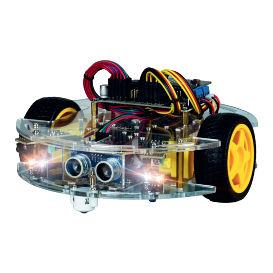
- Page 4 JOY-CAR The Joy-Car is a modular built education kit for Robotics. It serves for learning of building parts and their function inside a whole machine. Learning is especially easy because of the detailled manual and the programming. Joy-Car has sensors like the line-finder or the ultra sonic senor as well as a programmable RGB-lighting.
- Page 5 COMPONENTS Welcome to your own Joy-Car Assembly kit! There is much to discover, but you won‘t enter this journey alone! In the following chapters, we show you step by step, how you create your own, ridable project out of this assembly kit.
- Page 6 CHASSIS PARKING BATTER BRACKET C BASE BRACKETS A PARKING CHASSIS MOTOR BRACKETS BRACKETS B ULTRASONIC BATTERY BRACKET A SERVO BRACKET BRACKET SPACER BATTERY BRACKET B...
- Page 7 ELECTRONICS LINETRACKING- MAINBOARD BATTERY CASE SENSOR 3-PIN DUPONT- LED BOARD OBSTACLE-SENSOR CABLE SET 4-PIN DUPONT- SPEEDSENSOR SERVOMOTOR CABLE SET MICRO:BIT ULTRASONIC- MOTOR SENSOR NOT INCLUDED IN EVERY JOY- CAR SET!
- Page 8 ASSEMBLY MATERIAL SCREW SCREW SPACER 4x M2,5 x 5 mm 5x M3 x 14 mm 4x M2,5 x 10 mm SCREW WASHER SPACER 12x M2,5 x 10 mm 30x M2,5 4x M3 x 30 mm SCREW BALL CASTER 4x M2,5 x 22 mm 20x M2,5 SCREW CABLE TIE...
-
Page 9: Assembly
ASSEMBLY Before we start with your Joy-Car, it has to be assembled first. But no worries! Even though there are many components, modules and cables, we won‘t let you down. In this chapter, we show you step by step how you will assemble your Joy-Car. -
Page 10: Base Assembly
BASE DRIVE TRAIN BASE ASSEMBLY ELECTRONICS First, we assemble the base. Any brackets and spacers, that are necessary for the following steps, will be mounted now. ATTENTION! All acrylic parts are laminated with a protection foil. This foil must CHASSIS be removed before any assembly works. - Page 11 1. MOUNT SPACERS First, mount the 4 spacers (M3 x 30mm) to the base and secure them from below with the matching nuts (M3). 2. MOUNT ULTRASONIC BRACKET Mount the ultrasonic bracket to the base. Secure them from below with the matching screw (M3 x14 mm) and the matching nut (M3). ATTENTION! Advanced users can also mount the ultrasonic sensor moveable together with the servor motor onto the chassis top part (see for alternative ultrasonic assembly).
- Page 12 3. MOUNT BALL CASTERS Mount the ball casters to the base. For the front, use the screws from the ball caster. For the back, use the M2,5 x10mm screws. ATTENTION! Use the spacer for the mounting of the ball caster at the rear axle.
-
Page 13: Drive Train Assembly
BASE DRIVE TRAIN ELECTRONICS DRIVE TRAIN ASSEMBLY As next step, we assemble the drive train and mount it on the Joy-Car. The drive train contains the motors and is therefore responsible for the propulsion of the Joy-Car. CHASSIS ULTRASONIC ALTERNATIVE ASSEMBLY... - Page 14 1. PRE-ASSEMBLE THE MOTORS Put both motors into the ducts of the motor brackets and secure them with the matching screws (M2.5 x22mm) and nuts (M2.5). Additionally use two washers (M2.5) per screw, one on the screw head and one on the screw end. Afterwards, put the black perforated disk on the inner side of the motor.
-
Page 15: Electronics Assembly
BASE DRIVE TRAIN ELECTRONICS ELECTRONICS ASSEMBLY Next, we insert all electronic components into the base. This includes not only the individual sensors, but also the LED modules which are used as headlights. CHASSIS ULTRASONIC ALTERNATIVE ASSEMBLY WIRING FINISH... - Page 16 1. FRONT HEADLIGHTS Insert the WS2812B LED headlight modules into the front of the base. Secure them with the cable ties. You can simply insert the cable tie through the hole of the headlights and the hole of the base and set it tight.
- Page 17 3. LINETRACKING-SENSORS Mount the linetracking-sensors at the bottom side with the matching screws (M2.5 x10mm) and nuts (M2.5). Use 2 washers per screw (M2.5). 4. SPEED-SENSORS Insert the speed-sensors into the bottom side of the base. Secure them with the matching screws (M2.5 x 10mm) and nuts (M2.5). Again, use 2 flat washers (M2.5) per screw.
- Page 18 5. ULTRASONIC-SENSOR Insert the ultrasonic-sensor into the bracket. If needed, you can additionally secure it with some glue. The 4 connection pins need to point upwards. ATTENTION! If you should have decided to assemble the ultrasonic- sensor on a moveable servo motor at the second step of the base assembly procedure, then please skip this step.
-
Page 19: Chassis Assembly
BASE DRIVE TRAIN ELECTRONICS CHASSIS ASSEMBLY The base is now ready. We will now start with the chassis. This includes, besides the mainboard bracket, the obstacle sensors. CHASSIS ULTRASONIC ALTERNATIVE ASSEMBLY WIRING FINISH... - Page 20 1. ATTACH SPACERS Attach the 4 spacers (M2.5 x10mm) onto the chassis and secure them from below with the matching nuts (M2.5). ATTENTION! Please mind that the two highlighted holes are located on the left side of the driving direction. 2.
- Page 21 BASE DRIVE TRAIN ULTRASONIC-ALTERNATIVE-ASSEMBLY ELECTRONICS The ultrasonic-sensor can alternatively be mounted on the chassis. Here, it will be installed with a servo Motor and thereby offers a bigger measurement area. If you prefer this variant and have skipped the mount on the base, you can continue with this chapter.
- Page 22 1. ATTACH SERVO ARM Attach the servo arm onto the gear head of the motor. Secure it with the screw delivered with the motor. 2. INSERT SERVO MOTOR Now insert the servo motor into the slot on the chassis. But the cable of the motor first, then the motor.
- Page 23 3. ASSEMBLE THE ULTRASONIC-BRACKET Assemble the bracket onto the bracket of the servo motor and screw them with the matching screw (M3 x 14mm) and nut (M3). 4. MOUNT THE ULTRASONIC BRACKET Place the ultrasonic-bracket onto the servo motor arm and secure it with the delivered cable ties.
-
Page 24: Wiring
DRIVE TRAIN WIRING ELECTRONICS Now it is time to wire the electronic components to the mainboard of the Joy-Car. ATTENTION! The mainboard, chassis and base are not screwed together yet. But now is the best time to connect and lay the cables easily before connecting the three units together. - Page 25 The 3 linetracking-sensors are each connected with a 3 pin cable. The other cable end can be lead through the holes in the base L M R and the chassis and can be connected to the board of the Joy-Car. RECOMMENDED CABLE ATTENTION! The sensor‘s sensitivity can be adjusted additionally.
- Page 26 2. WIRE THE SPEED-SENSORS The 2 speed sensors are also connected with a 3-pin cable each and connected to the board of the Joy-Car. WARNING! The speed-sensors have 4 pins, but are only connected with a 3-pin cable. The remaining pin is not connected.
- Page 27 3. WIRE THE HEADLIGHTS The 4 headlight modules are each connected with a 4-pin cable and conducted to the mainboard of the Joy-Car.
- Page 28 4. WIRE THE ULTRASONIC-SENSOR The ultrasonic-sensor is connected with the mainboard by a 4-pin cable as well.
- Page 29 Both motors are already pre-wired with two cables. These are conducted to the terminal screws on the side of the board of the Joy-Car. Here you will need a screwdriver to loosen and secure the clamps again, after you have inserted the cables.
- Page 30 The battery cases are also pre-wired with 2 cables, just like the motors before. These are secured at the corresponding clamps on the board of the Joy-Car, as well. Thereby, the red cable is destined for the ‚+‘ clamp and the black cable is destined for the ‚-‘...
- Page 31 7. WIRE THE OBSTACLE SENSORS The 2 obstacle sensors have 4 pin headers, but only require 3 cables. They are therefore connected with a 3-pin cable only and conducted to the board. WARNING! The obstacle-sensors have 4 pins, but are only connected with a 3-pin cable. The remaining pin is not connected.
- Page 32 8. OPTIONAL: WIRE THE SERVO MOTORS If you have mounted the ultrasonic-sensor with a servo motor in the alternative ultrasonic assembly, then the servo motor will be connected with a 3-pin cable to the first servo motor connector. You can also optionally connect a second servo motor, which you can use for individual programming. In case you have neither used the alternative ultrasonic assembly nor wish to install an optional servo, please skip this step.
- Page 33 BASE DRIVE TRAIN ELECTRONICS FINISH You are almost done! Since now everything is monted and wired, we will now attach the chassis to the base, secure the mainboard and insert the Micro:Bit. CHASSIS ULTRASONIC ALTERNATIVE ASSEMBLY WIRING FINISH...
- Page 34 4 spacers using the matching screws(M3 x 8mm). 2. MAINBOARD Now put the mainboard of the Joy-Car onto the already mounted spacers on the chassis and secure it with the 4 matching screws (M2.5 x 5mm).
- Page 35 3. INSERT THE MICRO:BIT Now insert your micro:bit into the brackets of the mainboard and make sure the two buttons point upward. ATTENTION! Depending on the model, the micro:bit might not be included and has to be purchased separately. 4. PARKING BRACKETS Take the two big parking brackets B and insert two of the parking bracket holders A in each.
- Page 36 Joy-Car won‘t drive away when you try out your code. The assembly of your Joy-Car is now completed. You can now either proceed with the next chapter, where we explain the function of the single sensors step by step and how these can be utilised, or you spring ahead to the programming.
- Page 37 You are still unsure about the wiring of your joy car? You still don't know where to run the cables and somehow everything doesn't look right? Have a look at our example wiring, how you can lead the cables best and at which places you can connect them with cable ties, so that the wiring of your joy car also makes a good impression.
-
Page 38: Training
TRAINING Your Joy-Car is assembled and freshly polished? Great! But you cannot start driving yet. In this chapter, we will go into detail and explain the modules, how they work and how they communicate with the Joy-Car. This knowledge will help you in your own projects. -
Page 39: Sensors
SENSORS ULTRASONIC-SENSOR The ultrasonic-sensor can be used with the Joy-Car for detection of objects and obstacles in a range between 2 and 300 cm. Therefore, it can avoid obstacles with a bigger distance or even can ride towards the objects. - Page 40 OBSTACLE-SENSOR The obstacle sensor can detect objects near the Joy-Car. For this purpose, the LED infrared light is radiated to the front. If an object / obstacle enters this light beam, the light is reflected and can be detected by the infrared receiver. The range of this sensor can be adjusted with the potentiometers.
- Page 41 Your sensors are correctly adjusted when the LED on each sensor lights up, when the Joy-Car is on the sheet of paper and when the LEDs turn out again when you put the Joy- Car on the tape.
-
Page 42: Communication
(master), and all other devices only wait for permission to transmit and are therefore called slaves. I2C is used in the Joy-Car for communication and control of the infrared sensors (IO Expander) and the motor control unit (PWM controller). - Page 43 PWM stands for „Pulse Width Modulation“. With this method, the ratio of the switch-on time to the defined period duration is varied. Pulse width modulation is used to control the speed or brightness of loads such as motors or LEDs. The duration of a period is usually a few milliseconds or less.
- Page 44 „Din“ (data in) and a „Dout“ (data out) pin. These pins are used to connect the boards together. To keep the wiring clear, the LED boards are not directly connected to the bus line. The bus line is led back to the mainboard of the Joy-Car and is routed from the „Dout“...
- Page 45 The IO-Expander is a central unit on your Joy-Car, to which most of the sensors are connected. Since the micro:bit does not have enough inputs for all sensors, these are connected to the IO expander. This then communicates with the micro:bit via the I2C interface.
-
Page 46: Details
This way you can activate two more pins for your own development, if you need them. ON/OFF To switch your Joy-Car on or off, you don‘t have to insert or remove the batteries again and again. You can easily disconnect the power supply via the on/off switch. ON/OFF... - Page 47 POWER SUPPLY In the assembly instructions, you have already learned that you can connect the battery holder to the BAT terminal. However, if you should make your own modifications, you are not bound to the battery holder. Here it is good to know: You can connect any voltage source between 4.5-9V to the BAT terminal.
- Page 48 The mainboard of the Joy-Car is of course only the connecting unit between the individual sensors and modules and the micro:bit. You want to know where and how the individual units are connected to the micro:bit? Or maybe you want to make changes yourself? On our schematic diagram we have summarized all units and show you how they are controlled by the micro:bit.
-
Page 49: Agony Of Choice
MakeCode and „Mu for MicroPython“ are both development environments. In principle, there is no right or wrong here. With both variants you can use all functions of your Joy-Car and also create your own applications on the Joy- Program Car. -
Page 50: Makecode
And yet, this system introduces you to programming and prepares you for practical programming. With MakeCode, for example, it can be child‘s play to make the Joy-Car drive and stop it as soon as an obstacle is detected: ... - Page 51 A NEW START 論 At the beginning, each project consists of two basic blocks: the „on start“-block and the „forever“-block. All instructions within these two blocks are executed by the program. However, the „on start“-block is only executed once when you start your program.
- Page 52 OVER AND OVER AGAIN... Even loops can be easily mapped with the blocks. Here you can execute something until the condition is no longer met („during“-block) or repeat something based on a certain number („repeat x times“-block). ON THE LOOKOUT! In the left area of your project window you will find the block overview, with all blocks that are available to you.
-
Page 53: The First Start
THE FIRST START A NEW CHAPTER You have no experience with the MakeCode development environment yet, but would like to start with a small example? We‘ll get you the lay of the land! On HTTPS://MAKECODE.MICROBIT.ORG/ you will get to the development environment. Here we go, as soon as you enter the site. - Page 54 All you have to do is give your new project a name and you‘re good to go. GIVE A NAME TO YOUR PROJECT HERE THEN CONFIRM YOUR ENTRY Next you start directly in the development environment and you can put together your first blocks. For your first project we will now create a small sample project together.
- Page 55 You will see that the block overview has enlarged and the category you just clicked on has opened. TAKE THE „SHOW LEDS“-BLOCK AND SIMPLY DRAG IT WITH YOUR MOUSE INTO THE „AT START“-EXECUTION-BLOCK You can click the individual boxes and set which of the LEDs you want to be activated.
- Page 56 But that was only the part that is executed once at startup. Now drag the „show text“ block and a „pause“ block from the Basics category into your „permanent“ execution block. TAKE THE „SHOW LEDS“-BLOCK AND DRAG IT WITH YOUR MOUSE INTO YOUR „AT START“-EXECUTION-BLOCK You can also change the text and also the duration of the pause by clicking on the white fields.
- Page 57 Your first sample code is ready and can now be trans- ferred to your micro:bit. First connect your micro:bit to your computer. In most cases, your micro:bit should be automatically recognized and paired, so your code can be conveniently downloaded directly to your device. CLICK HERE FOR AUTOMATIC TRANSFER.
- Page 58 Even though the browser may not have recognized your micro:bit, it should still have been recognized as a drive in your Windows Explorer. HERE YOU CAN OPEN YOUR MICRO:BIT AS DEVICE Then copy your programming that you have downloaded before into the disk folder of your micro:bit.
- Page 59 We put together all functions of the Joy-Car in a separate extension for you. To use it for your project, first open the tab Advanced in your block overview and click on Extensions. Now search for Joy-Car and click on our extension. It will then automatically be added to your project.
-
Page 60: Joy-Car
ALL IN ONE PLACE After you have added the Joy-Car extension to your project via the extension menu, you will find the Joy-Car tab in your block overview. Here all the functions of the Joy-Car are combined, so you can start right away. The functions are categorized by motors, lighting, sensors and other functions. - Page 61 The blocks of the Joy-Car extension give you access to all functions of your Joy-Car. So you can customize your blocks and your entire programming. On the following pages we have provided you with every single block and explains its function.
- Page 62 MOTORS The motors are the drive of the Joy-Car. You can move the Joy-Car back and forth, drive at different speeds, turn and brake. The two servo motors can also be controlled in this category. DRIVE MOTOR DELAY BRAKE Drive forwards or backwards.
- Page 63 HEADLIGHTS The four LED modules, the headlights of the Joy-Car, can be controlled in this category. So you can control the front head- lights, activate turn signals and brake lights and find even more functions here. HEADLIGHTS HAZARDLIGHTS INDICATOR Set the indicator for one side (left/right) of the The headlights are controlled here.
- Page 64 SENSORS The sensors on your Joy-Car allow you to react to certain events. Obstacles, lines, markings and speed? The sensors on your Joy-Car can detect that. LINEFINDER-SENSOR SPEED-SENSORS Checks the left/center/right linefinder sensor whether a line on Checks the left/right speed-sensor whether the signal the floor could be detected.
- Page 65 ADDITIONAL FUNCTIONS Here you can find more functions of the Joy-Car, which go beyond the previous motor funtions, sensor queries and light settings. BATTERY VOLTAGE BUZZER Play a predefined melody with the Buzzer. You can additionally The battery voltage can be queried over the analog to digital converter pin of the micro:bit.
-
Page 66: All The Way
MAXIMUM FUN, MINIMUM EFFORT? You prefer to drive right away? You can also, instead of developing your Joy-Car yourself, use our prepared script on your micro:bit. Here the most important functions are already arranged in an application with three different modes. - Page 67 MICROPYTHON INTRODUCTION MICROPYTHON? MicroPython is an implementation based on the Python 3 language. It was written in the C programming language and is optimized for use on microcontrollers such as the micro:bit. Users who are already familiar with the basics of software programming can start directly with this variant.
- Page 68 INTERFACE SETUP When starting the Mu Editor for the first time, it is first necessary to select the desired mode. Select BBC MICRO:BIT here and confirm the choice with OK. The detailed English MicroPython documentation can offer additional help and can be found here.
- Page 69 CHECK Hereby, the written source code can be checked. Mistakes are automatically detected and displayed accordingly. FLASH The written source code is checked, compiled for the micro:bit and then transferred to the device. CONTROL ELEMENTS CODE-AREA REPL IN-/OUTPUT-AREA...
- Page 70 THE FIRST START A NEW CHAPTER You have no experience yet with the MU development environment but you prefer to start with a small example? We are showing you the environment! After the start of the development environment, you begin with an empty Project.
- Page 71 It is best to start with a simple test. Feel free to take over the left example. The text "Hello world!" will be displayed on the LED matrix of your micro:bit and on the console. INSERT YOUR CODE HERE WHEN YOU ARE FINISHED, CLICK ON FLASH TO DOWNLOAD THE CODE TO YOUR CONNECTED MICRO:BIT.
- Page 72 We have divided the programming of the Joy-Car for you into 12 files. This way you will get to know every function, unders- tand and can put together what you need for your own development. We have put together the following files for you: IO_EXPANDER_READ.PY...
-
Page 73: Io_Expander_Read.py
IO_EXPANDER_READ.PY All sensor information is read by the IOExpander via I2C here. The readout is done by the function fetchSensorData(). No pass parameters are needed here. The return value is a dictionary which contains the following information: Speed-Sensor Left Speed-Sensor Right LineTracking-Sensor Left LineTracking-Sensor Center... -
Page 74: Adc_Read.py
Joy-Car and the rc_remote.py on the micro:bit you want to use as remote control. Tilt the micro:bit with the remote program and your Joy-Car will drive in that direction. On button A you use the horn. Button B turns on the light. -
Page 75: Demo.py
Mode 0: Standby, Mode 1: Linefollowing, Mode 2: Obstacle detection and avoidance SONAR.PY This script shows you how to use the sonar of the Joy-Car. The function sonar() does not expect arguments and returns the measured distance to the next object in cm. SERVO.PY ... - Page 76 Your Joy-Car is now ready for action. You can either develop your own programming or try out our sample codes and get to know the functions of your Joy-Car. All files and examples can be found for download on our Joy-Car-Website.
- Page 77 We also support you after your purchase! If you have any questions left or if you encounter any problems please feel free to contact us by mail, phone or via ticket-supportsystem on our website. E-Mail: service@joy-it.net Ticket-System: http://support.joy-it.net Phone: +49 (0)2845 9360 – 66 (10 - 17 Uhr) Please visit our website for more information: www.joy-it.net...
Need help?
Do you have a question about the JOY-CAR and is the answer not in the manual?
Questions and answers