
Related Manuals for KUHN GF502


Summary of Contents for KUHN GF502
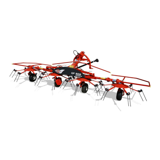
- Page 1 Operator's manual KN245BGB_B Read carefully before starting the machine Gyrotedder Original instructions KN245BGB_B - English - 07-2019...
-
Page 3: Dear Owner
1. Dear Owner In buying a Kuhn machine you have chosen wisely. Into it have gone years of thought, research and improvement. You will find, as have thousands of owners all over the world, that you have the best that engineering skill and actual field testing can produce. -
Page 4: Table Of Contents
Gyrotedder GF502 2. Contents Dear Owner ........................3 Contents ..........................4 Identification of the machine..................7 Rear view ............................7 Rear view (transport position) ......................7 Identification of the machine ......................8 3.3.1 Location of the plates ......................8 3.3.2 Description.......................... 8 Optional equipment........................10 Safety.......................... - Page 5 Gyrotedder GF502 Road safety equipment and recommendations ................29 4.4.1 Tyre pressure ........................30 4.4.2 Instructions specific to France..................30 4.4.3 Instructions specific to Italy ....................30 Likely critical failures........................30 Incorrect use of the machine by the user ..................31 Limit state criteria...........................
- Page 6 Gyrotedder GF502 Optional equipment......................53 Lateral signalling equipment ......................53 Tine arm deflectors ........................53 DUPLEX gearbox .......................... 53 9.3.1 Machine use ........................54 Europe signalling equipment ......................55 9.4.1 Coupling and uncoupling ....................55 USA signalling equipment......................56 9.5.1 Coupling and uncoupling ....................56 Three point frame damper ......................
-
Page 7: Identification Of The Machine
Gyrotedder GF502 3. Identification of the machine Rear view Rear view (transport position) 3. - Identification of the machine KN245BGB_B... -
Page 8: Identification Of The Machine
3.3.1 Location of the plates - Please write below the type and serial number of the machine. • Serial Number: - This information is to be given to the Kuhn authorized dealer for any spare parts order or warranty claim. 3.3.2 Description ... - Page 9 Gyrotedder GF502 Certification plate (CE) For machines aimed at countries which are 26: Model Year members of the European Union (EC marking). 24: Year of Construction 7: Model KUHN logo 9: Serial Nr. Model Machine serial number Plate reference...
-
Page 10: Optional Equipment
Gyrotedder GF502 Optional equipment Lateral signalling equipment. Tine arm deflectors. DUPLEX gearbox. Signalling. USA signalling equipment. Support wheel. Three point frame damper. Wheel deflectors. Lower hitch pins. Female coupler. ... -
Page 11: Safety
Gyrotedder GF502 4. Safety Description of symbols used in this document This symbol indicates a potentially hazardous situation that if not avoided, could result in serious bodily injury. This symbol is used to identify special instructions or procedures which, if not followed strictly, could result in machinery damage. -
Page 12: Safety Instructions
Never let anyone operate the machine who is not trained to do so. Should you have any difficulties in understanding any parts of this manual, please contact your KUHN dealer. 4.2.3 Precautions to be taken before carrying out any operations on the machine... -
Page 13: Precautions To Take Before Using The Machine
Gyrotedder GF502 4.2.4 Precautions to take before using the machine Do not wear loose clothing which could become caught up in moving parts. Wear the appropriate protective clothing for the work in hand (gloves, shoes, goggles, helmet, ear defenders, etc.). -
Page 14: Precautions When Driving On Public Roads
Gyrotedder GF502 4.2.6 Precautions when driving on public roads Dimensions Depending on the dimensions of the machine, contact the relevant authorities to ensure that it can be legally transported on public roads. If the machine is over the maximum legal size, follow the local regulations for special transportation of oversize equipment. - Page 15 Gyrotedder GF502 Gross weight and weight per axle The drawings are not legally binding, their only aim is to illustrate the method to use. Prior to driving on public roads, check that all criteria are met to be in conformity with the...
- Page 16 Gyrotedder GF502 How to proceed: Stage 1: To measure: - Tractor tare (T). T = _____kg T = ________ kg Stage 2: - Couple the machine to the tractor. To measure: - Load on front axle (t1): • Tractor + machine (transport position).
- Page 17 Gyrotedder GF502 Stage 3: To measure: - Total weight (t): • Tractor + machine (transport position). • Ballast weights. Checking: - To go to the next stage: • Check in the tractor's operator's manual that the value measured is below the tractor's Gross Combined Weight Rating.
-
Page 18: Maximum Speed
Gyrotedder GF502 4.2.7 Maximum speed - Always keep to the legal speed limit for driving a tractor-machine assembly on public roads. 4.2.8 Precautions when coupling Before attaching the machine, make sure that it cannot accidentally start moving (chock the wheels) and that the parking stand is in the right position. -
Page 19: Hydraulic Circuit
Gyrotedder GF502 4.2.9 Hydraulic circuit Caution! The hydraulic circuit is under high pressure. Maximum pressure at work: 200 bar (2901 psi). Before connecting hoses to the tractor hydraulics, ensure that tractor and machine circuits are not under pressure.Before disconnecting a hose, depressurize the hydraulic circuit. -
Page 20: Pto Shaft
Gyrotedder GF502 4.2.10 PTO shaft Use only PTO shafts supplied with the machine or recommended by the machine manufacturer. The protective shield of the tractor PTO stub, the PTO shaft guards and the protective shield of the machine input shaft must always be in place and in good condition. - Page 21 Gyrotedder GF502 Before engaging the PTO drive, make sure that there are no people or animals near the machine. Never engage the PTO drive when the tractor engine is stopped. Do not install any adapter device that results in a portion of the tractor PTO stub, the rotating PTO shaft, or the adapter to be unguarded.
-
Page 22: Precautions During Manoeuvres
Gyrotedder GF502 4.2.11 Precautions during manoeuvres When moving the machine from the transport position to the working position and vice versa, make sure that nobody is within the machine pivoting area. 4.2.12 Remote controlled components Danger of crushing and shearing can exist when components are operated by hydraulic or pneumatic controls. -
Page 23: Waste Disposal
For your own safety and for correct machine operation, only use original manufacturer parts. It is strongly recommended to have your machine checked by your Kuhn dealer after each season, especially tools and their attaching hardware (nuts, bolts, etc.). 4. - Safety... -
Page 24: Projection Of Stones And Foreign Objects
Gyrotedder GF502 4.2.17 Projection of stones and foreign objects For driver safety, always use a tractor equipped with a cab. Never start the machine when there are people nearby. Even when the machine is used in accordance with its purpose, objects may be projected. Stones and other foreign objects projected by the moving parts can travel a considerable distance. -
Page 25: Precautions To Take Before Using The Parking Stands
Gyrotedder GF502 4.2.19 Precautions to take before using the parking stands 134138: Specific requirements for countries member of the Eurasian Economic Community (EAC marking). 134139: Specific requirements for countries member of the Eurasian Economic Community (EAC marking). 133983: Specific requirements for countries member of the Eurasian Economic Community (EAC marking). - Page 26 Gyrotedder GF502 Location and description of safety decals on the machine 4.3.1 Location of safety decals 4. - Safety KN245BGB_B...
- Page 27 Gyrotedder GF502 4.3.2 Description of safety decals Operating instructions (1) The operators' manual contains all the information necessary for using the machine safely. It is imperative to read and comply with all instructions. Working on the machine (2)
- Page 28 Gyrotedder GF502 Body crushing (5) Stay a safe distance from the machine. Crushing hazard. 4. - Safety KN245BGB_B...
-
Page 29: Road Safety Equipment And Recommendations
Road safety equipment and recommendations The road safety equipment is mounted in the factory or by your authorized Kuhn dealer according to current safety regulations. - Always keep to the legal speed limit for driving a tractor-machine assembly on public roads. -
Page 30: Tyre Pressure
Gyrotedder GF502 4.4.1 Tyre pressure • (1):2.0 bar (29 psi). 4.4.2 Instructions specific to France The machine must be fitted with specific signalling panels to comply with the road regulations. 4.4.3 Instructions specific to Italy The machine must be fitted with specific signalling panels to comply with the road regulations. -
Page 31: Incorrect Use Of The Machine By The User
Gyrotedder GF502 Incorrect use of the machine by the user 133996: Specific requirements for countries member of the Eurasian Economic Community (EAC marking): • 133998: Specific requirements for countries member of the Eurasian Economic Community (EAC marking). • 133999: Specific requirements for countries member of the Eurasian Economic Community (EAC marking). -
Page 32: Machine Specifications
5.1.1 Designated use of the machine The GF502 gyrotedder must only be used for the purpose for which it was manufactured: spreading and tedding previously cut forage or straw. It can also be used to form small windrows in order to limit the exposure of crop to dew at night. -
Page 33: Technical Specifications
Gyrotedder GF502 Technical specifications GF502 Attachment type 3 point linkage category 1 and 2 Number of rotors Number of tine arms per rotor Working width (DIN11220) 5.00 m (16’4’’) Width in working position 5.43 m (17’9’’) Length in working position 2.31 m (7’6’’) -
Page 34: Required Equipment
Gyrotedder GF502 Required equipment The machine is factory fitted with the following equipment: 5.3.1 Primary PTO shaft The machines are factory fitted with one of the following PTO shafts: • PTO shaft 1 3/8’’ - 6 splines. • PTO shaft 32x38 - 8 splines. -
Page 35: Sound Levels
Gyrotedder GF502 Sound levels Sound levels have been measured in accordance with the measuring methods as defined in: NF EN ISO 4254-1 «Agricultural machinery - Safety - Part 1: General requirements» Weighted equivalent continuous acoustic pressure level at the driver's seat (closed cabin) L (A) eq: Tractor only: 78.7 dB(A) -
Page 36: Putting Into Service
Gyrotedder GF502 6. Putting into service Description of control elements The machine is fitted with the following components: • 1 outer wing release cord accessible from the tractor cab. • 1 hydraulic hose for manoeuvring the outer sections. 6. - Putting into service... -
Page 37: Coupling And Uncoupling
Gyrotedder GF502 Coupling and uncoupling 6.2.1 Preparing the tractor Check that the tractor's authorized gross weight as well as its lift capacity and maximum weight per axle are not exceeded. See section: - Safety Safety instructions Precautions when driving on public roads. - Page 38 Gyrotedder GF502 Hitch pin parallelism - Adjust tractor lift rods so that hitch pins are parallel to the ground. Lateral adjustment of the lower links - Distribute the play on each side of the lift linkage. - Check that the stabilisers function properly (Adjustment, Locking / Unlocking).
-
Page 39: Coupling The Machine
Gyrotedder GF502 6.2.2 Coupling the machine - Lower the tractor three-point linkage. - Position tractor lower links in line with machine lower yokes. Category 1 linkage - Place lower links in position (a). - Secure each lower link with lynch pin. -
Page 40: Hydraulic Connection
Gyrotedder GF502 - (a) Pivot lock (1). The top link can be placed in 3 different positions: - Select the position according to the tractor coupling points and the length of the top link. - (b) Attach top link to the machine swinging yoke top hitch pin. -
Page 41: Primary Pto Shaft
Gyrotedder GF502 6.2.4 Primary PTO shaft Before using the machine for the first time: - Grease the transmission. - Check overlap of the u-joint drive shaft and adjust length if necessary to avoid any premature wear. K9C186TL The direction of rotation is shown on a decal. - Page 42 Gyrotedder GF502 Never operate the PTO shaft at an angle X exceeding 30°. To avoid serious accidents, the PTO drive shaft guards must be properly in place and fixed with the chains provided. - Attach PTO shaft guard chain in hole (1) on machine side.
-
Page 43: Uncoupling The Machine
Gyrotedder GF502 6.2.5 Uncoupling the machine Before carrying out any maintenance or repairs on the machine, switch off the tractor engine, remove ignition key, wait until all moving parts have come to a standstill and apply park brake. - Park the machine on an even fairly level ground. - Page 44 Gyrotedder GF502 - Detach the top link from the machine end. - Release lower links from hitch pins (1). - Move forward with the tractor. The machine is uncoupled. The machine can be parked in working position. 6. - Putting into service...
-
Page 45: Instructions For Transport
Gyrotedder GF502 7. Instructions for transport Before placing the machine into transport position: - Wait until the rotating parts have come to a complete stop. - Check that nobody is within the machine pivoting area. - If there is someone, make sure the person moves away. - Page 46 Gyrotedder GF502 - Lower rotor pivot lock (1). - Pivot rotor by 180 degrees. - Check that the rotor pivot lock is fully engaged. - Repeat procedure on second rotor. - Lift the machine with the tractor's three point linkage.
-
Page 47: Conformity With The Road Regulations
Gyrotedder GF502 Conformity with the road regulations - Before driving the machine on public roads, ensure that the machine complies with current highway code regulations. - Check that reflectors are clean. - Check that transport locks (1) are fully engaged. -
Page 48: Instructions For Work
Gyrotedder GF502 8. Instructions for work Before placing the machine in working position: - Check that nobody is within the machine pivoting area. - If there is someone, make sure the person moves away. Putting the machine into work position... -
Page 49: Putting The Machine In Headland Turn Position
Gyrotedder GF502 - Pivot lock (1) to unlock swinging yoke (2). - Lower the tractor three-point linkage to rest the machine on the ground. - Activate transport position cylinders to release stop pins. - Pull release cord until stop pins are released. -
Page 50: Adjustments In Working Position
Gyrotedder GF502 Adjustments in working position Before adjusting, maintaining or repairing the machine, turn off ignition key and wait until all moving parts have come to a complete stop. 8.3.1 Pitch angle adjustment - Lower the tractor three-point linkage to rest the machine on the ground. -
Page 51: Adjustment Of The Travel Range For Work On Slopes
Gyrotedder GF502 8.3.3 Adjustment of the travel range for work on slopes - Adjust stops located between the first and second unit. To increase the downward travel range With the machine in transport position: - Remove screw (1). - Remove one or two washers (2). -
Page 52: Machine Use
Gyrotedder GF502 Machine use - When optional equipment is used, follow specific procedures mentioned in the related section: Optional equipment/ DUPLEX gearbox. 8.4.1 Groundspeed and PTO speed The following factors determine the forward speed: • The humidity level (This factor is particularly determining when wilting). -
Page 53: Optional Equipment
Gyrotedder GF502 9. Optional equipment Lateral signalling equipment The machine must be fitted with specific signalling panels to comply with the road regulations. Tine arm deflectors This equipment helps prevent hay from becoming trapped by the tine arms and rotor housings during work. -
Page 54: Machine Use
Gyrotedder GF502 9.3.1 Machine use To tedd (a): - Connect PTO shaft to the central gearbox input shaft. - Fit PTO cover inside the guard to protect the non used pto stub. For forming night windrows (b): - Connect PTO shaft to the DUPLEX gearbox input shaft. -
Page 55: Europe Signalling Equipment
Gyrotedder GF502 Europe signalling equipment 9.4.1 Coupling and uncoupling Electrical connection - Connect 7-pin plug to the tractor. Removal - Disconnect and store 7-pin plug in its holder. 9. - Optional equipment KN245BGB_B... -
Page 56: Usa Signalling Equipment
Gyrotedder GF502 USA signalling equipment 9.5.1 Coupling and uncoupling Electrical connection - Connect 7-pin plug to the tractor. Removal - Disconnect and store 7-pin plug in its holder. Three point frame damper The stabilizer (1) is recommended for work on irregular grounds or slopes. -
Page 57: Support Wheel
Gyrotedder GF502 Support wheel The prop wheel provides better adaptation to irregular ground contours. 9.7.1 Putting into service Uncoupling the machine - Do not park the machine on the prop wheel. 9.7.2 Instructions for transport Putting the machine into transport position - Insert and lock pin using R-clip (1). -
Page 58: Machine Use
Gyrotedder GF502 9.7.4 Machine use - Place the machine in working position. - Remove R-clip (1). - Remove pin (2). - Lower the support wheel (3) until in contact with the soil. - Reinstall hitch pin (2). - Reinstall R-clip (1). -
Page 59: Lower Hitch Pins
Gyrotedder GF502 9.10 Lower hitch pins This equipment allows extending the 3-point frame arms when the tractor coupling height is insufficient: - The coupling height is increased by 125 mm (5’’). 9.11 Female coupler 9. - Optional equipment KN245BGB_B... -
Page 60: Maintenance And Storage
Gyrotedder GF502 10. Maintenance and storage Before carrying out any maintenance or repairs on the machine, switch off the tractor engine, remove ignition key, wait until all moving parts have come to a standstill and apply park brake. - Check that hydraulic hose valves are shut- off. -
Page 61: Lubrication
Gyrotedder GF502 Grease: • The outer wing pivot pins. • The DIGIDRIVE coupling fingers. • The rotor hubs. • The rotor housings. Level control: • Central gearbox. Maintenance Check: • Tightness of all bolts and nuts. -
Page 62: Primary Pto Shaft
Gyrotedder GF502 10.2.1 Primary PTO shaft Before using the machine for the first time: - Grease the transmission. During intensive with tractors maximum authorized power, recommended to grease at closer intervals. Every 8 hours: • U-joints (1). Every 20 hours: •... - Page 63 Gyrotedder GF502 • The outer wing pivot pins. • The DIGIDRIVE coupling fingers. • The rotor hubs. 10. - Maintenance and storage KN245BGB_B...
-
Page 64: Level Control
Gyrotedder GF502 • The rotor housings. 10.2.4 Level control Central gearbox The central gearbox is lubricated with 0.8 kg (1.76 lb) multi-purpose grease grade NLGI2. - Check the main gearbox oil content: From the working position: - Remove 4 bolts (1). -
Page 65: Replacing A Tine
Gyrotedder GF502 10.3.2 Replacing a tine Before leaving tractor before adjusting, maintaining or repairing the machine, disengage the PTO drive, turn off the engine, remove ignition key and wait until all moving parts have come to a complete stop and apply park brake. - Page 66 Gyrotedder GF502 - Respect mounting instructions so that the crop's pressure (a) closes the coils. - Replace tine. - Check attachment bolt, washer and nut. Replace if necessary. - Reassemble the unit. - Check that the tine is properly embedded in the tine arm.
-
Page 67: Storage
Gyrotedder GF502 10.4 Storage 10.4.1 At the end of each season - Clean the machine thoroughly. - Fully lubricate the machine. - Grease the cylinder rods in contact with the outside. - Check tyre pressure: • 2.0 bar (29 psi). -
Page 68: Storage
Gyrotedder GF502 10.4.3 Storage • 139884: Specific requirements for countries member of the Eurasian Economic Community (EAC marking). • 139885: Specific requirements for countries member of the Eurasian Economic Community (EAC marking). • 139886: Specific requirements for countries member of the Eurasian Economic Community (EAC marking). -
Page 69: Appendix
Gyrotedder GF502 11. Appendix 11.1 Calculating the load on an axle When coupling a tool to the front and/or rear 3-point lift linkage, the maximum authorized payload must not be exceeded. When coupling tools to the front and/or rear 3-point lift linkages, the maximum load on tractor's tires must not be exceeded. - Page 70 Gyrotedder GF502 Obtained Description Units Description Tractor unladen weight Unladen load on tractor front axle Empty load on tractor rear axle Axle loads (Tractor + machine) Load on front axle (Tractor + machine) Load on rear axle (Tractor + machine)
- Page 71 Gyrotedder GF502 Front tool: 2) Calculation of the minimum front ballast weight M2 minimum a T2 b – 0 45 ---------------------------------------------------------------------------- - M2minimum minimum - Write the minimal additional weight in the chart. 3) Calculation of the actual load on the front axle T1...
- Page 72 Gyrotedder GF502 Table: Actual value obtained Value authorized Double value of the by calculation according to authorized capacity operator's manual per tyre (2 tyres) Minimum front/rear ballasting Total weight < Load on front axle < < Load on rear axle <...
- Page 73 Gyrotedder GF502 - T1: Load on front axle. • Tractor only. T1 = _____kg T1 = ________ kg - T2: Load on rear axle. • Tractor only. T2 = _____kg T2 = ________ kg - T: Axle loads. • Tractor only.
- Page 74 Gyrotedder GF502 Rear tool or front-rear combination: If the total unit weight exceeds the tractor Gross Combined Weight Rating in accordance with the countrie's legislation, empty the hopper to travel on public roads. In any case, we recommend to travel on public roads with empty hoppers and tanks.
- Page 75 Gyrotedder GF502 Calculating the rear tool weight (M2): M2 = t - T Calculating the distance (d): d = (( b x ( T1 - t1) ) / M2 ) - c Front tool: If the total unit weight exceeds the tractor Gross Combined Weight Rating in accordance with the countrie's legislation, empty the hopper to travel on public roads.
- Page 76 Gyrotedder GF502 - t: Axle loads. • Tractor + machine. t = _____kg t = ________ kg Calculating the front tool weight M1 = t - T Calculating the distance (a): a = ( b x ( T2 - t2) ) / M1 11.
-
Page 77: Limited Warranty
KUHN equipment from an authorized KUHN dealer, that such equipment is, at the time of delivery to such purchaser, free from defects in material and workmanship, and that such equipment is covered under this Limited Warranty providing the machine is used and serviced in accordance with the recommendations in the Operator's manual. - Page 78 - The warranty claim is completed on line via extranet - www.kuhn.com or submitted on a KUHN warranty claim form and returned to the Company within one month after the date of failure or the date of problem becoming apparent.
- Page 79 $Specimen of the "Declaration of conformity" EC Declaration of conformity (European directive 2006/42/CE) The manufacturer: Manufacturer name and address declares that the product described hereafter: Brand Brand Machine Machine Type / Model : Type / Model Serial no. Serial no. - conforms to the requirements of the European directive 2006/42/CE.
- Page 80 KUHN S.A. - B.P. 50060 - F - 67706 SAVERNE CEDEX (FRANCE) KUHN-AUDUREAU SAS - B.P. 19 - F - 85260 LA COPECHAGNIERE (FRANCE) KUHN-BLANCHARD SAS - 24, route de Nantes - F - 44680 CHEMERE (FRANCE) KUHN-HUARD SAS - B.P. 49 - F - 44142 CHATEAUBRIANT CEDEX (FRANCE) KUHN-GELDROP B.V.
Need help?
Do you have a question about the GF502 and is the answer not in the manual?
Questions and answers