Table of Contents
Advertisement
Quick Links
Advertisement
Table of Contents

Related Manuals for Campbell SoilVUE 10


Summary of Contents for Campbell SoilVUE 10
- Page 1 Revision: 11/2022 Copyright © 2019 – 2022 Campbell Scientific, Inc.
-
Page 2: Table Of Contents
Table of contents 1. Introduction 2. Precautions 3. Initial inspection 4. QuickStart 5. Overview 6. Specifications 7. Installation 7.1 Wiring 7.2 CRBasic programming 7.3 Siting 7.4 Field installation 8. Operation 8.1 SDI-12 measurements 8.2 Measurements at fast scan rates 8.3 Measurement theory 9. - Page 3 B.10.1 Changing an SDI-12 address Table of Contents - ii...
-
Page 4: Introduction
Although the SoilVUE 10 is rugged, it should be handled as a precision instrument. The depth of the hole in which the SoilVUE 10 will be installed must match the SoilVUE 10 length. Mark the installation tool to align with the length of the probe to ensure the proper depth is obtained. -
Page 5: Initial Inspection
RF sources such as ac power lines and motors. 3. Initial inspection Upon receipt of the SoilVUE 10, inspect the packaging and contents for damage. File any damage claims with the shipping company. The model number and cable length are printed on a label at the connection end of the cable. - Page 6 3. In the Available Sensors and Devices box, type SoilVUE10 or locate the probe in the Sensors > Soil folder. Double-click SoilVUE10 Complete Soil Profiler. Type the correct SDI-12 Address; default address is 0. The Probe length defaults to 0.5 m; to change this, click the Probe length box and select 1 m.
- Page 7 6. In Output Setup, type the scan rate, meaningful table names, and Data Output Storage Interval. CAUTION: The scan rate must be evenly divisible into 15 or 60 minutes (depending on the Measure every selected in step 3). The 0.5 m probe can take one minute, and the 1.0 m probe can take one and a half minutes, to complete measurements.
-
Page 8: Overview
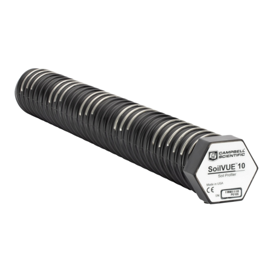
5. Overview The SoilVUE 10 uses time-domain reflectometry (TDR) to measure soil volumetric water content (VWC) and electrical conductivity (EC). The waveguides (measurement rods) are embedded in threads and centered on the measurement depths of 5, 10, 20, 30, 40, and 50 cm for the 0.5 m... -
Page 9: Specifications
The SoilVUE 10 should be installed in a hole made by a standard 5-cm (2-in) hand auger tool. Auger the hole to the proper depth and screw the SoilVUE 10 into the hole (see Field installation [p. 9]). Water should be used to lubricate the sides of the hole to aid in installation and to ensure the probe is not damaged due to excessive force. - Page 10 For more information, refer to Soil- specific calibration procedure for volumetric water content sensors available on the Campbell Scientific website. Permittivity: ±1 permittivity unit between 4 and 42 permittivity Electrical conductivity: ±2% (0 to 2.5 dS/m), ±5% (full range) Temperature: ±0.15 °C between –30 and 40 °C...
-
Page 11: Installation
For the CR6 and CR1000X data loggers, triggering conflicts may occur when a companion terminal is used for a triggering instruction such as TimerInput(), PulseCount(), or WaitDigTrig(). For example, if the SoilVUE 10 is connected to C3 on a CR1000X, C4 cannot be used in the TimerInput(), PulseCount(), or WaitDigTrig() instructions. -
Page 12: Siting
For more information on installation, watch a video at www.campbellsci.com/videos/soilvue10 Proper installation of the SoilVUE 10 is critical. This includes selecting a monitoring site that is representative of the soil of interest, ensuring good contact between the waveguides and the surrounding soil, minimizing disturbance to the soil, and minimizing preferential flow of water along the probe. - Page 13 The installation kit is not necessary to install the SoilVUE 10. A standard 5-cm (2-in) hand auger may be used instead of the auger supplied in the kit. The SoilVUE 10 can then be inserted into the hole using a standard six-sided 2.25-inch socket.
- Page 14 a. Care should be taken to ensure the sides of the hole are even and parallel and do not become tapered with repeated removal of soil. b. Wet the sides of the hole to reduce the force needed to install the probe. In most cases, the hole will need to be thoroughly wetted.
-
Page 15: Operation
When the top of the probe is flush with the soil surface, the top sensor is at 5 cm (2 in) depth. 5. Connect the cable to the SoilVUE 10, and hand tighten the cable connector nut to ensure a water-tight seal. Do not over tighten. The cable nut should turn easily. If it does not, check to make sure it is correctly aligned. - Page 16 60 seconds. A C! command does not require the data logger to pause its operation until the values are ready. Table 8-1: SoilVUE 10 SDI-12 commands SDI-12 command Values returned or function Units 1. Volumetric water content, 5 cm 2.
- Page 17 Table 8-1: SoilVUE 10 SDI-12 commands SDI-12 command Values returned or function Units 1. Volumetric water content, 40 cm 2. Relative permittivity (ɛ), 40 cm aM5! or aC5! 3. Temperature, 40 cm °C 4. Bulk electrical conductivity, 40 cm dS/m 1.
- Page 18 Table 8-1: SoilVUE 10 SDI-12 commands SDI-12 command Values returned or function Units 11. Temperature, 20 cm °C 12. Bulk electrical conductivity, 20 cm dS/m 13. Volumetric water content, 30 cm 14. Relative permittivity (ɛ), 30 cm 15. Temperature, 30 cm °C...
-
Page 19: Measurements At Fast Scan Rates
8.3 Measurement theory The SoilVUE 10 is a multiparameter soil profile probe that measures soil volumetric water content using a time-domain reflectometry (TDR) method. The probe consists of TDR circuitry connected to a series of six or nine helical waveguides that makeup part of the overall threaded design. -
Page 20: Maintenance And Troubleshooting
“Statement of Product Cleanliness and Decontamination” form. Refer to Assistance page near the end of this manual for more information. The SoilVUE 10 does not require periodic maintenance. For troubleshooting, Table 9-1 (p. 17) provides symptoms, possible causes, and solutions. -
Page 21: References
10. References Topp, G.C., J.L. Davis & A.P. Annan. 1980. “Electromagnetic determination of soil water content: measurements in coaxial transmission lines,” Water Resources Research, v. 16, No. 3:574-582. Ledieu, J., P. De Ridder, P. De Clerck, and S. Dautrebande. 1986. “A method of measuring soil moisture by time-domain reflectometry,”... -
Page 22: Appendix A. Importing Short Cut Code Into Crbasic Editor
Appendix A. Importing Short Cut code into CRBasic Editor Short Cut creates a .DEF file that contains wiring information and a program file that can be imported into CRBasic Editor. By default, these files reside in the C:\campbellsci\SCWin folder. Import Short Cut program file and wiring information into CRBasic Editor: 1. -
Page 23: Appendix B. Sdi-12 Sensor Support
Serial Data Interface at 1200 baud (SDI-12) is a protocol developed to simplify sensor and data logger compatibility. Only three wires are necessary—serial data, ground, and 12 V. With unique addresses, multiple SDI-12 sensors can connect to a single SDI-12 terminal on a Campbell Scientific data logger. -
Page 24: Acknowledge Active Command (A!)
Table B-1: Campbell Scientific sensor SDI-12 command and response set Command Name Response Address query a<CR><LF> aAb! Change address b<CR><LF> Start measurement atttn<CR><LF> aM1!...aM9! Start measurement aMC! atttn<CR><LF> aMC1!...aMC9! and request CRC Start concurrent measurement atttnn<CR><LF> aC1!...aC9! aCC! Start doncurrent measurement atttnn<CR><LF>... -
Page 25: Start Verification Command (Av!)
Where a = sensor address ll = SDI-12 version number (indicates compatibility) cccccccc = eight-character vendor identification mmmmmm = six characters specifying the sensor model vvv = three characters specifying the sensor version (operating system) xxx…xx = up to 13 optional characters used for a serial number or other specific sensor information that is not relevant for operation of the data logger <CR><LF>... -
Page 26: Start Measurement Commands (Am!)
A sensor address is changed with command aAb!, where a is the current address and b is the new address. For example, to change an address from 0 to 2, the command is 0A2!. The sensor responds with the new address b, which in this case is 2. NOTE: Only one sensor should be connected to a particular terminal at a time when changing addresses. -
Page 27: Stopping A Measurement Command
B.8 Stopping a measurement command A measurement command (M!) is stopped if it detects a break signal before the measurement is complete. A break signal is sent by the data logger before most commands. A concurrent measurement command (C!) is aborted when another valid command is sent to the sensor before the measurement time has elapsed. - Page 28 Transparent mode is entered while the computer is communicating with the data logger through a terminal emulator program. It is accessed through Campbell Scientific data logger support software or other terminal emulator programs. Data logger keyboards and displays cannot be used.
- Page 29 4. Select the correct Communication Port and click Connect. 5. Click the Terminal tab. 6. Select All Caps Mode. 7. Press Enter until the data logger responds with the data logger (CR1000X>) prompt. 8. Type SDI12 and press Enter. 9. At the Select SDI12 Port prompt, type the number corresponding to the control port where the sensor is connected and press Enter.
- Page 30 response Entering SDI12 Terminal indicates that the sensor is ready to accept SDI-12 commands. 10. To query the sensor for its current SDI-12 address, type ?! and press Enter. The sensor responds with its SDI-12 address. If no characters are typed within 60 seconds, the mode is exited.
- Page 31 See Product Details on the Ordering Information pages at www.campbellsci.com . Other manufacturer's products, that are resold by Campbell Scientific, are warranted only to the limits extended by the original manufacturer. Refer to www.campbellsci.com/terms#warranty for more information.
- Page 32 To obtain a Returned Materials Authorization or Repair Reference number, contact your CAMPBELL SCIENTIFIC regional office. Please write the issued number clearly on the outside of the shipping container and ship as directed. For all returns, the customer must provide a “Statement of Product Cleanliness and Decontamination”...
- Page 33 Do not recharge, disassemble, heat above 100 °C (212 °F), solder directly to the cell, incinerate, or expose contents to water. Dispose of spent batteries properly. WHILE EVERY ATTEMPT IS MADE TO EMBODY THE HIGHEST DEGREE OF SAFETY IN ALL CAMPBELL SCIENTIFIC PRODUCTS, THE CUSTOMER ASSUMES ALL RISK FROM ANY INJURY RESULTING FROM IMPROPER INSTALLATION, USE, OR MAINTENANCE OF TRIPODS, TOWERS, OR...
- Page 34 Campbell Scientific Regional Offices Australia France Thailand Location: Garbutt, QLD Australia Location: Vincennes, France Location: Bangkok, Thailand Phone: 61.7.4401.7700 Phone: 0033.0.1.56.45.15.20 Phone: 66.2.719.3399 Email: info@campbellsci.com.au Email: info@campbellsci.fr Email: info@campbellsci.asia Website: www.campbellsci.com.au Website: www.campbellsci.fr Website: www.campbellsci.asia Brazil Germany Location: São Paulo, SP Brazil...
Need help?
Do you have a question about the SoilVUE 10 and is the answer not in the manual?
Questions and answers