Sign In
Upload
Manuals
Brands
Allied Telesis Manuals
Switch
8100L Series
Allied Telesis 8100L Series Manuals
Manuals and User Guides for Allied Telesis 8100L Series. We have
1
Allied Telesis 8100L Series manual available for free PDF download: Installation Manual
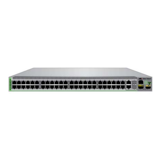
Allied Telesis 8100L Series Installation Manual (116 pages)
Fast Ethernet Switches
Brand:
Allied Telesis
| Category:
Switch
| Size: 0 MB
Table of Contents
Table of Contents
5
Preface
13
Document Conventions
14
Contacting Allied Telesis
15
Chapter 1: Overview
17
Features
18
8100L and 8100S Models
18
10/100 Mbps Twisted Pair Ports
18
Fiber Optic Ports
18
Power over Ethernet
19
10/100/1000 Mbps Twisted Pair Ports
19
SFP Slots
19
Stacking Ports
20
Leds
20
Installation Options
20
MAC Address Table
20
Management Software and Interfaces
20
Management Methods
20
Fanless Models
21
8100L Series Switches
22
Hardware Features
22
Table 1: Hardware Features of the 8100L Series Switches
22
Front Panels
23
Front Panel Components
23
Figure 1: Front Panels of the 8100L Series Switches
23
Figure 2: Networking Ports and SFP Slots on the 8100L Series Switches
23
8100S Twisted Pair Series Switches
24
Hardware Features
24
Table 2: Hardware Features of the 8100S Twisted Pair Series
24
Front Panels
25
Figure 3: Front Panels of the 8100S Twisted Pair Series Switches
25
Front Panel Components
26
Figure 4: Networking Ports and SFP Slots on the 8100S Series Switches
26
8100S Fiber Optic Series Switches
27
Hardware Features
27
Table 3: Hardware Features of the Fiber Optic 8100S Series Switches
27
Front Panels
28
Figure 5: Front Panels of the 8100S Fiber Optic Series Switches
28
Fiber Optic Ports
29
Figure 6: Front Panels of the 8100S Fiber Optic Series Switches (Continued)
29
Table 4: General Specifications of the Fiber Optic Ports
29
Back Panels
30
Figure 7: Back Panels of the Single Power Supply Switches
30
Figure 8: Back Panels of the Dual Power Supply Switches
31
Management Panels
32
Figure 9: 8100L Series Management Panel
32
Figure 10: 8100S Series Management Panel
32
Model Naming Conventions
33
Figure 11: Model Naming Conventions for the Twisted Pair 8100L and 8100S Series Switches
33
Figure 12: Model Naming Conventions of the Fiber Optic 8100S Series Switches
33
Table 5: Model Naming Conventions for the Twisted Pair 8100L and 8100S Series Switches
33
Table 6: Model Naming Conventions for the Fiber Optic 8100S Series Switches
34
10/100Base-TX Twisted Pair Ports
35
Speed
35
Duplex Mode
35
Wiring Configuration
35
Maximum Distance
36
Power over Ethernet
36
Cable Requirements
36
Port Pinouts
36
Table 7: Twisted Pair Cable Requirements for the 10/100Base-TX Ports
36
10/100/1000Base-T Twisted Pair Ports
37
Speed
37
Duplex Mode
37
Wiring Configuration
37
Maximum Distance
38
Power over Ethernet
38
Cable Requirements
38
Port Pinouts
38
Table 8: Twisted Pair Cable for the 10/100/1000Base-T Ports
38
SFP Slots
39
Table 9: Combo Ports
39
Power over Ethernet
41
Poe Standards
41
Powered Device Classes
42
Power Budget
42
Table 10: IEEE Powered Device Classes
42
Port Prioritization
43
Wiring Implementation
44
Stacking Ports
45
Eco-Friendly Button
46
Leds
47
10/100Base-TX Twisted Pair Port Leds
47
Figure 13: 10/100Base-TX Port Leds
47
Table 11: 10/100Base-TX Port Leds
47
10/100/1000Base-T Twisted Pair Port Leds
48
Figure 14: 10/100/1000Base-T Port Leds
48
Table 12: 10/101000Base-T Port Leds
48
100Base-FX Port Leds
49
Figure 15: 100Base-FX Port LED
49
Table 13: 100Base-FX Port LED
49
SFP Slot LED
50
Figure 16: SFP Slot Leds
50
Table 14: SFP Slot LED
50
Stacking Port Leds
51
Stack ID LED
51
Figure 17: Stacking Port S1 and S2 Leds
51
Table 15: Stacking Port S1 and S2 Leds
51
Figure 18: Stack ID LED
52
Console Port
53
Power Supplies
54
Power Connectors
55
Chapter 2: Beginning the Installation
57
Installation Procedures
58
Reviewing Safety Precautions
59
Choosing a Site for the Switch
63
Unpacking the Switch
64
8100L Series Switches
64
Figure 19: Components of the 8100L Series Switches
65
8100S Series Switches
66
Figure 20: Components of the 8100S Series Switches
66
AT-8100S/24C Switch
67
Figure 21: Components of the AT-8100S/24C Switch
67
Chapter 3: Installing the Switch on a Table or in an Equipment Rack
69
Installing the Switch on a Table or Desktop
70
Installing the Switch in an Equipment Rack
71
Figure 22: Turning the Switch Upside down
71
Figure 23: Removing the Rubber Feet
71
Figure 24: Attaching the Brackets to Install the Switch in an Equipment Rack
72
Figure 25: Attaching the Brackets to Install the Switch in an Equipment Rack (Continued)
73
Figure 26: Attaching the Brackets to 8100L and AT-8100S/24C Switches for Equipment Rack Installation
74
Figure 27: Attaching the Brackets to 8100L and AT-8100S/24C Switches for Equipment Rack Installation (Continued)
75
Figure 28: Mounting the Switch in an Equipment Rack
75
Chapter 4: Cabling the Networking Ports
77
Cabling the Twisted Pair and Fiber Optic Ports
78
Twisted Pair Ports
78
Fiber Optic Ports
79
General Guidelines
79
Installing Optional SFP Transceivers
80
Figure 29: Removing the Dust Plug from an SFP Slot
81
Figure 30: Installing an SFP Transceiver
81
Figure 31: Removing the Dust Cover from the SFP Module
82
Figure 32: Positioning the SFP Handle in the Upright Position
82
Figure 33: Connecting the Fiber Optic Cable to the SFP Module
83
Chapter 5: Powering on the Switch
85
Powering on an AC Switch
86
Figure 34: Plugging in the AC Power Cord
86
Monitoring the Initialization Processes
87
Table 16: Leds and Management Software Initialization
88
Figure 35: Switch Initialization Messages
89
Figure 36: Switch Initialization Messages (Continued)
90
Powering on a DC Switch
91
Figure 37: DC Terminal Block
92
Figure 38: Stripped Wire
92
Figure 39: Inserting Wires into the DC Terminal Block
93
Setting the Stack ID Number
95
Starting a Local Management Session
95
Figure 40: Connecting the Management Cable to the Console Port
95
Starting a Telnet Management Session
96
Changing the Stack ID Number
97
Figure 41: Alliedware Plus Command Line Prompt
97
Figure 42: Moving to the Global Configuration Mode with the ENABLE and CONFIGURE TERMINAL Commands
97
Figure 43: STACK Command Confirmation Prompt
98
Starting a Management Session
99
Local Management
99
Telnet Management
99
Secure Shell Management
100
Web Browser Management
100
Snmp
101
Specifying Ports in the Command Line Interface for Stand-Alone Switches
101
Figure 44: PORT Parameter in the Command Line Interface
101
Chapter 6: Troubleshooting
103
Appendix A: Technical Specifications
107
Physical Specifications
107
Table 17: Product Dimensions
107
Table 18: Product Weights
107
Environmental Specifications
108
Table 19: Ventilation Requirements
108
Table 20: Environmental Specifications for All Switches Except the AT-8100L/8POE-E Switch
108
Table 21: Environmental Specifications for the AT-8100L/8POE-E Switch
108
Power Specifications
109
Table 22: Maximum Power Consumptions
109
Table 23: Input Voltages
109
Certifications
110
Quality and Reliability
110
Table 24: Product Certifications
110
Table 25: MTBF
110
RJ-45 Twisted Pair Port Pinouts
111
Figure 45: RJ-45 Socket Pin Layout (Front View)
111
Table 26: Pin Signals for 10 and 100 Mbps
111
Fiber Optic Port Specifications
112
Table 27: Pin Signals for 1000 Mbps
112
Table 28: Fiber Optic Port Specifications for the AT-8100S/16F8-SC Switch
112
Table 29: Fiber Optic Port Specifications for the AT-8100S/16F8-LC and AT-8100S/24F-LC Switches
113
RJ-45 Style Serial Console Port Pinouts
114
Stacking Port Pinouts
114
Figure 46: Stacking Port Pin Layout (Front View)
114
Table 30: RJ-45 Style Serial Console Port Pin Signals
114
Table 31: Stacking Port Pin Signals
114
Advertisement
Advertisement
Related Products
Allied Telesis AT 8000/8POE
Allied Telesis Rapier 8/8MT
Allied Telesis Rapier 8/8SC
Allied Telesis Rapier 8
Allied Telesis Rapier 8MT
Allied Telesis Rapier 8SC
Allied Telesis Rapier 8/8
Allied Telesis 8100S Series
Allied Telesis Series
Allied Telesis SwitchBlade *8106
Allied Telesis Categories
Switch
Network Router
Media Converter
Network Hardware
Wireless Access Point
More Allied Telesis Manuals
Login
Sign In
OR
Sign in with Facebook
Sign in with Google
Upload manual
Upload from disk
Upload from URL