Table of Contents
Advertisement
Quick Links
TABLE OF CONTENTS
Receiving Instructions
After delivery, remove the packaging from the product. Inspect the product closely to determine
whether it sustained damage during transport. If damage is discovered, record a complete description of it
on the bill of lading. If the product is undamaged, discard the packaging.
NOTE: The end-user is solely responsible for confirming that product design, use, and maintenance comply
with laws, regulations, codes, and mandatory standards applied where the product is used.
Technical Service & Replacement Parts
For answers to questions not addressed in these instructions and to order replacement parts, labels, and
accessories, call our Technical Service and Parts Department at (260) 665-7586. The department can also
be contacted online at https://www.vestil.com/page-parts-request.php.
Electronic Copies of Instruction Manuals
Additional copies of this instruction manual may be downloaded from
manuals.php.
Signal
Words...............................................................................................................................
Safety
Instructions........................................................................................................................
Specifications............................................................................................................................
National
Standards.....................................................................................................................
Installing the
Baler......................................................................................................................
Assembling the
Baler..................................................................................................................
CBB-3000-37 Exploded View & Bill of
Power Unit Exploded View & Bill of
Power Unit Subassembly Exploded View & Bill of
Motor/Pump Exploded View & Bill of
Manifold Subassembly Exploded View & Bill of
Hydraulic Circuit
Diagram...........................................................................................................
Manifold, Pressure Switches, and
208-230V AC Standard Single Phase Electrical Circuit
208-230/460V AC Standard 3-Phase Electrical Circuit
Using the
Baler............................................................................................................................
Record of Satisfactory
Inspections &
Maintenance.........................................................................................................
Labeling
Diagram.......................................................................................................................
Limited
Warranty.........................................................................................................................
TABLE OF CONTENTS
CBB-3000-37 CARDBOARD BALER
TABLE OF CONTENTS
Materials................................................................................
Materials..................................................................................
Materials..............................................................................
Valves........................................................................................
Condition.................................................................................................
Copyright 2022 Vestil Manufacturing Co.
Rev. 1/17/2023
Vestil Manufacturing Co.
2999 North Wayne Street, P.O. Box 507, Angola, IN 46703
Telephone: (260) 665-7586 -or- Toll Free (800) 348-0868
Fax: (260) 665-1339
www.vestil.com
Materials..............................................................
Materials.................................................................
Diagram.......................................................
Diagram.......................................................
CBB-3000-37 MANUAL
e-mail:
info@vestil.com
https://www.vestil.com/page-
PAGE
2
2
3
3
4
5
-
6
7,
8
9
10
10
11
11
12
13
14
15
-
16
16
-
17
17
18
19
Page 1 of 19
Advertisement
Table of Contents

Related Manuals for Vestil CBB-3000-37


Summary of Contents for Vestil CBB-3000-37
- Page 1 Specifications……………………………………………………………………………………………………………. National Standards……………………………………………………………………………………………………... Installing the Baler………………………………………………………………………………………………………. Assembling the Baler…………………………………………………………………………………………………… CBB-3000-37 Exploded View & Bill of Materials………..…………………………..…………..…………….…. Power Unit Exploded View & Bill of Materials………...……………….…………..…………………………….… Power Unit Subassembly Exploded View & Bill of Materials…………………………………………………….. Motor/Pump Exploded View & Bill of Materials………………………………….………………………………..
-
Page 2: Signal Words
SAFETY INSTRUCTIONS Vestil strives to identify foreseeable hazards associated with the use of its products, but no manual can address every conceivable risk. Minimize the likelihood of injury by observing the hazards identified below and by inspecting and maintaining the product as instructed in INSPECTIONS &... -
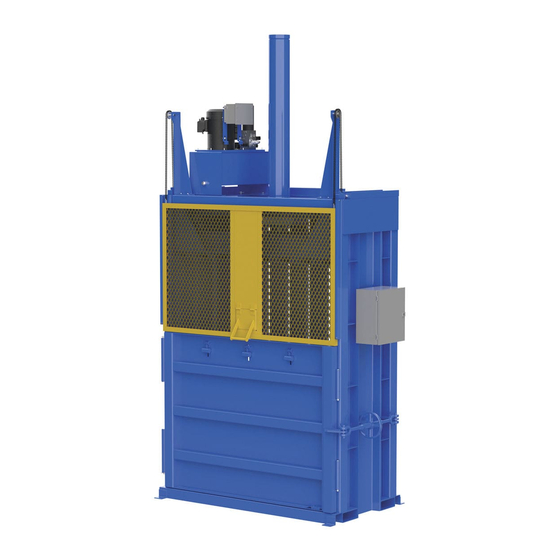
Page 3: Specifications
CBB-3000-37 MANUAL SPECIFICATIONS The CBB-3000-37 is a single-stage, vertical downstroke baler, i.e. single-stage baler in which the ram only travels up-and-down: A downward compression stroke and an upwards retraction stroke. A specifications document for CBB-3000-37 balers is available online to anyone who visits Vestil’s website. - Page 4 6” long (15.2cm). Drill holes at the marked locations according to the instructions provided with your anchoring hardware. Install anchor bolts through the bolt holes and tighten them against the mounting brackets (see arrows in diagram). TABLE OF CONTENTS Copyright 2022 Vestil Manufacturing Co. Page 4 of 19...
- Page 5 Install the retaining ring in this groove. Attach the remaining idler sprocket to the sprocket peg of the right pulley weldment. TABLE OF CONTENTS Copyright 2022 Vestil Manufacturing Co. Page 5 of 19...
- Page 6 17) Connect the baler to the appropriate power source as shown in the applicable electrical circuit diagram on page 13 (208-230V AC; 1-phase) or page 14 (208-230V/460V AC; 3-phase). TABLE OF CONTENTS Copyright 2022 Vestil Manufacturing Co. Page 6 of 19...
- Page 7 TABLE OF CONTENTS Rev. 1/17/2023 CBB-3000-37 MANUAL CBB-3000-37 EXPLODED VIEW (BILL OF MATERIALS ON FOLLOWING PAGE) 22-006-023 TABLE OF CONTENTS Copyright 2022 Vestil Manufacturing Co. Page 7 of 19...
- Page 8 TABLE OF CONTENTS Rev. 1/17/2023 CBB-3000-37 MANUAL CBB-3000-37 BILL OF MATERIALS (22-006-023) ITEM PART NO. DESCRIPTION QTY. ITEM PART NO. DESCRIPTION QTY. 22-002-023 FINAL ASSEMBLY W/O POWER UNIT 22-537-003 WELDMENT, DYNAMIC STOP 22-514-066 WELDMENT, EJECT HOOK 1.41 22-514-065 WELDMENT, COUNTERWEIGHT...
- Page 9 99-031-016 HYDRAULIC, 3/4" PIPE PLUG BLACK NPT ELECTRICAL ENCLOSURE, 99-029-130 8" X 6" X 4", ROUGH Shown in detail in POWER UNIT SUBASSEMBLY EXPLODED VIEW on p. 10. TABLE OF CONTENTS Copyright 2022 Vestil Manufacturing Co. Page 9 of 19...
- Page 10 LOCK WASHER Z PLATED, 11107 33626 16 x 1-1/4" Ø 1/2 HEX BOLT, GRADE A, ZINC PLATED, HEX NUT, GRADE A, ZINC 11205 36106 1/2"-13X 1" PLATED, 3/8-16 TABLE OF CONTENTS Copyright 2022 Vestil Manufacturing Co. Page 10 of 19...
- Page 11 GA2 = SYSTEM OPERATING PRESSURE. NEVER EXCEED 2500 PSI GA3 = NO NEED TO TEST GA4 = PRESSURE REQURED TO RAISE UL-GA = PRESSURE AT WHICH THE LARGE PUMP UNLOADS TABLE OF CONTENTS Copyright 2022 Vestil Manufacturing Co. Page 11 of 19...
- Page 12 22-127-027 22-127-027 Counterbalance valve (CBV) 99-153-114 Relief valve (RV) Pressure Sequence 99-153-078 switch (PS) valve (SEQ) 99-022-004 99-153-028 FIG. 7: Left side view FIG. 8: Right side view TABLE OF CONTENTS Copyright 2022 Vestil Manufacturing Co. Page 12 of 19...
- Page 13 TABLE OF CONTENTS Rev. 1/17/2023 CBB-3000-37 MANUAL 208-230V AC STANDARD SINGLE PHASE ELECTRICAL CIRCUIT DIAGRAM 22124033 FIG. 9: Standard 3-phase electrical circuit diagram TABLE OF CONTENTS Copyright 2022 Vestil Manufacturing Co. Page 13 of 19...
- Page 14 TABLE OF CONTENTS Rev. 1/17/2023 CBB-3000-37 MANUAL 208-230V/460V AC STANDARD 3-PHASE ELECTRICAL CIRCUIT DIAGRAM 22124032 TABLE OF CONTENTS Copyright 2022 Vestil Manufacturing Co. Page 14 of 19...
- Page 15 Close the gate. Press and hold both the CYCLE START and DOWN buttons until the platen stops and the red stack light turns on. Then, press the red E-STOP button on the control box. TABLE OF CONTENTS Copyright 2022 Vestil Manufacturing Co. Page 15 of 19...
- Page 16 Compare the results of all inspections to this record to determine whether the unit is in satisfactory condition. Do not use the baler unless it is in satisfactory condition. Purely cosmetic changes, like damaged paint/powdercoat, do not constitute changes from satisfactory condition. However, TABLE OF CONTENTS Copyright 2022 Vestil Manufacturing Co. Page 16 of 19...
-
Page 17: Inspections & Maintenance
8. Finish: Repair areas where the finish has been damaged. Use steel wool or a steel bristle brush to remove rust before applying touchup paint to the affected areas. TABLE OF CONTENTS Copyright 2022 Vestil Manufacturing Co. Page 17 of 19... -
Page 18: Labeling Diagram
L: Close Gate Label control box) (applied to gate) R: PPE Label (applied near control box) Q: Lockout Label (applied P: Tipping Hazard Label near control box) (on back of baler) TABLE OF CONTENTS Copyright 2022 Vestil Manufacturing Co. Page 18 of 19... -
Page 19: Limited Warranty
Warrantee (you) for warranty service. Who may request service? Only a warrantee may request service. You are a warrantee if you purchased the product from Vestil or from an authorized distributor AND Vestil has been fully paid. Definition of “original part”? An original part is a part used to make the product as shipped to the Warrantee.
Need help?
Do you have a question about the CBB-3000-37 and is the answer not in the manual?
Questions and answers