Table of Contents
Advertisement
Quick Links
ALPHA EX & MIR APPROVED DIESEL
PUMP WITH FUEL CONTROL SYSTEM
- ALPHA/50WAFC
Please read carefully before commencing installation
Registered Office: HYTEK (GB) LIMITED, Delta House, Green Street, Elsenham, Bishop's Stortford
Tel: +44 (0) 1279 815 600 Fax: +44 (0) 1279 812 978 email: info@hytekgb.com
Technical Data
Applies to the following models only:
- ALPHA/70WAFC - ALPHA/90WAFC
CM22 6DS UK. Registered in England No. 1915382
Web:
www.hytekgb.com
S886/3
Advertisement
Table of Contents

Related Manuals for Hytek ALPHA/50WAFC


Summary of Contents for Hytek ALPHA/50WAFC
- Page 1 - ALPHA/70WAFC - ALPHA/90WAFC Please read carefully before commencing installation Registered Office: HYTEK (GB) LIMITED, Delta House, Green Street, Elsenham, Bishop’s Stortford CM22 6DS UK. Registered in England No. 1915382 Tel: +44 (0) 1279 815 600 Fax: +44 (0) 1279 812 978 email: info@hytekgb.com Web: www.hytekgb.com...
-
Page 2: Environmental Information
ENVIRONMENTAL INFORMATION UK Regulation requires that the equipment SI/2013/3113 bearing this symbol on the product and/or its packaging must not be disposed of with unsorted municipal waste. The symbol indicates that this product must be disposed of separately from regular household waste streams. It is your responsibility to dispose of this and other electric and electronic equipment via designated collection facilities appointed by the government or local authorities. -
Page 3: Important Warning Notes
IMPORTANT WARNING NOTES 1. On above ground storage tanks, an angle check valve fitted with the appropriate spring or pressure regulating valve must be fitted at the tank outlet to prevent loss of fuel under gravity in the event of vandalism or accidental damage. -
Page 4: Installation Instructions
INSTALLATION INSTRUCTIONS 1. Check you have the following items: 1 off Alpha FC10 pump 1 off delivery hose 2 off front door keys 2. Open the front panel using the key provided. 3. Remove the rear panel, if necessary, and store safely. MOUNTING 4. -
Page 5: Battery Backup Power
ELECTRICAL 8. Remove the cover from the junction box. 9. Connect a constant 220/240V AC 50 Hz supply, fused at 16 amps, to the terminal block in the junction box as shown on the wiring details diagram. NB: The Alpha pump must have a continual 220/240V AC supply, even when not in use. -
Page 6: Maintenance
PHOTO 2 BACKUP BATTERY POWER LEAD. MAINTENANCE The Alpha should require minimum maintenance in normal regular use, but as with all mechanical apparatus regular servicing will prolong its life and ensure maximum efficiency & reliability. The following should be carried out every 12 months or 1 million litres which ever comes first. - Page 7 USING THE FC10 FUEL CONTROL UNIT ALPHA PUMP TERMINAL FEATURES The Alpha Pump Terminal pictured below is fitted into the front of the Alpha fuel dispenser. FEATURES: Display: This shows pump totals as well as user information and instructions. The display is backlit to allow the pump to be used in all light conditions.
- Page 8 THE ALPHA PUMP TERMINAL IN STANDBY MODE This is when the Alpha Pump Terminal is powered up, with the display illuminated, but not in use. DISPLAY INFORMATION: Total Pump 1: This is the number shown in the top left-hand corner of the display screen.
- Page 9 FUELLING FROM THE ALPHA PUMP TERMINAL THE FUELLING PROCEDURE: a.) Insert Data Tag into the Data Tag Reader Slot. The display will show the Data Tag ID number and the registration number of the vehicle the Data Tag is allocated to. b.) If a message for the vehicle user is stored on the system, it will be displayed.
- Page 10 ALPHA BASE AND SUCTION CONNECTION DIAGRAMS BASE VIEW FROM ABOVE FRONT FOUR 15MM DIA. MOUNTING HOLES ALL DIMENSIONS IN MM SUCTION INLET LOCATION REAR VIEW 1 1/2" STAINLESS STEEL FLEXIBLE CONNECTOR (SUPPLIED AS STANDARD) 76.5MM DIA. ALTERNATIVE SUCTION HOLE SLOTTED TO BOTTOM OF 1 1/2"...
- Page 11 ALPHA DISPLAY CONNECTIONS DETAILS INTERNAL WIRING INTERNAL WIRING CONNECTIONS TERMINAL 1 CONNECTIONS TERMINAL 2 (LOWER) (UPPER) 240V AC 2 3 4 5 6 7 8 9 10 2 3 4 5 6 7 8 9 10 POWER INPUT CONNECTOR ALPHA JUNCTION BOX CONNECTION DETAILS ALPHA FC10 MAIN JUNCTION BOX INSTALLATION WIRING DETAILS 220/240V CONNECTIONS RS485 OUTPUT CONNECTIONS...
- Page 12 ALPHA SIDE ACCESS PANEL VIEW ALPHA PUMP UNIT FILTER LOCATION PUMP UNIT FILTER LOCATION AS VIEWED FROM THE FRONT S886/3...
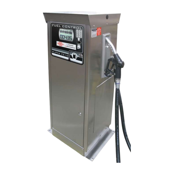
- Page 13 ALPHA FC10 EXTERNAL VIEW S886/3...
- Page 14 ALPHA FC10 INTERNAL VIEW S886/3...
- Page 15 ALPHA PARTS LIST DRG. PART DESCRIPTION PART NO. EXTERNAL COMPONENTS LOCK (x 2) ALP.LOCK.FC NOZZLE HOLSTER WITH SWITCH ALP.NOZBOOT.FC10 DOOR KEY ALP.KEY.FC OUTLET ELBOW ELB.4FFCR SIDE ACCESS PANEL ALP.ACCPAN3 MOUNTING BASE ALP.BASE3 TOP CAP ALP.CAP3 DOOR ALP.DOOR.FC3 SIDE PANEL ALP.SPAN.BL3 SIDE PANEL WITH HOSE OUTLET ALP.SPANH3 INTERNAL COMPONENTS...
-
Page 16: Declaration Of Conformity
Bishops Stortford, Hertfordshire, CM22 6DS, UK Date of Issue: January 2021 Equipment Details: Alpha ATEX Fuel Pumps with Fuel Control ALPHA/50WAFC, ALPHA/70WAFC, ALPHA/90WAFC Applicable Directives: SI 2016 1091 Electromagnetic Compatibility Regulations & Standards SI 2016 1101 Electrical Equipment Safety Regulations...
Need help?
Do you have a question about the ALPHA/50WAFC and is the answer not in the manual?
Questions and answers