Table of Contents
Advertisement
Quick Links
Technical Data
ALPHA ATEX APPROVED TWIN
DIESEL PUMP WITH FUEL
CONTROL SYSTEM
Applies to ATEX Certified Alpha Twin diesel / gas oil pumps only.
Please read carefully before commencing installation
Registered Office: HYTEK (GB) LIMITED, Delta House, Green Street, Elsenham, Bishop's Stortford
CM22 6DS UK. Registered in England No. 1915382
Tel: +44 (0) 1279 815 600 Fax: +44 (0) 1279 812 978 email: info@hytekgb.com
Web: www.hytekgb.com
S858/4
Advertisement
Table of Contents

Subscribe to Our Youtube Channel
Related Manuals for Hytek ALPHA


Summary of Contents for Hytek ALPHA
- Page 1 ALPHA ATEX APPROVED TWIN DIESEL PUMP WITH FUEL CONTROL SYSTEM Applies to ATEX Certified Alpha Twin diesel / gas oil pumps only. Please read carefully before commencing installation Registered Office: HYTEK (GB) LIMITED, Delta House, Green Street, Elsenham, Bishop’s Stortford CM22 6DS UK.
-
Page 2: Environmental Information
ENVIRONMENTAL INFORMATION European Directives 2012/19/EU requires that the equipment bearing this symbol on the product an/or its packaging must not be disposed of with unsorted municipal waste. The symbol indicates that this product must be disposed of separately from regular household waste streams. It is your responsibility to dispose of this and other electric and electronic equipment via designated collection facilities appointed by the government or local authorities. -
Page 3: Important Warning Notes
IMPORTANT WARNING NOTES 1. On above ground storage tanks, an angle check valve fitted with the appropriate spring or pressure regulating valve must be fitted at the tank outlet to prevent loss of fuel under gravity in the event of vandalism or accidental damage. 2. -
Page 4: Installation Instructions
INSTALLATION INSTRUCTIONS 1. Check you have the following items: 1 off Alpha twin pump 2 off delivery hoses 1 off front door key 2. Open the front panels using the key provided. 3. Remove the rear panels, if necessary, and store safely. - Page 5 ALPHA TWIN BASE AND SUCTION CONNECTION PIPEWORK 5. Connect the 11/2” diameter pipe from the tank to the suction inlet flexible connectors of the pump. The inlet threads of the flexible connector flanges are 11/2” BSP taper female. Seal the joints with a suitable thread-sealing compound. Alternative pipe work entry points, for above ground pipe work, are provided at the rear of the pump base.
- Page 6 NB:The Alpha pump must have a continual 220/240V AC supply, even when not in use 10. If the Alpha is to be operated in conjunction with a key/card system, remove the links in the junction box (shown on the Alpha Installation Wiring Diagram) and connect so that the control system makes and breaks the connections.
- Page 7 Maximum voltage - 50 volts Maximum power - 5 VA 12. Ensure all the terminal screws are tight and replace the junction box cover. ALPHA JUNCTION BOX WIRING DIAGRAM PUMP 2 PUMP 1 – FC10 PUMP 1 FC10 DISPLAY CONNECTIONS DETAILS...
- Page 8 PUMP 2 DISPLAY CONNECTION DIAGRAM CALIBRATION BUTTON DISPLAY / NEUTRAL 220/240 VAC CALCULATOR POWER EARTH AC INPUT VIEWED FROM INPUT LIVE REAR 220/240 VAC NEUTRAL - GREY PUMP MOTOR RELAY NOZZLE P/OUT SOLENOID SWITCHES PULSE IN COMMS LIVE - BLACK OUTPUT +12V CH1 CH2 GND...
-
Page 9: Maintenance
MAINTENANCE The Alpha should require minimum maintenance in normal regular use, but as with all mechanical apparatus regular servicing will prolong its life and ensure maximum efficiency & reliability. The following should be carried out every 12 months or 1 million litres which ever comes first. - Page 10 ALPHA PUMP UNIT FILTER LOCATION PUMP UNIT FILTER LOCATION AS VIEWED FROM THE FRONT ALPHA SIDE ACCESS PANEL VIEW S858/4...
- Page 11 PUMP 1 – FC10 FUEL CONTROL CALIBRATION Please use the GREEN engineer’s calibration tag to calibrate Pump 1 – FC10 Fuel Control Unit. (Stock code FC.TAGC) PUMP 2 – ALPHA DISPLAY CALIBRATION ELECTRONIC DISPLAY/CALCULATOR FEATURES 6-digit backlit Main LCD display: Up to 9999.99 or 99999.9 litres...
- Page 12 CALIBRATION PROCEDURE - (MUST BE CARRIED OUT TO ENSURE PUMP ACCURACY) 1. Ensure the nozzle is stowed in the holster and the dispenser is isolated from any fuel management systems. 2. Remove calibration button cover bolt from rear of display / calculator housing (if fitted).
- Page 13 Select 2 PULSE CHANNEL for Weights & Measures Alpha, REED PULSER for Alpha fitted with PULS.E18 reed switch pulser (pre August 2003) or Adblue Alpha and 1 PULSE CHANNEL for all other Alpha versions. 6. The lower line will show the following 00000.0...
-
Page 14: Opto Output
TANK SW UNUSED – No “tank empty” switch connected. CALIB TANK SW IS TA.F TANK SW IS TA.F – “Tank empty” switch connected is Hytek TA.F type* (*Feature coming soon) TANK SW NOT TA.F – “Tank empty” switch connected is standard “normally closed” float switch* (*Feature coming soon) 11. - Page 15 12. The lower line will show the following 00000.0 In a looping sequence: NOZ 2 SW UNUSED – No additional /remote nozzle switch connected. CALIB NOZ 2 SW UNUSED 2nd NOZ SW N/O– Additional nozzle switch is normally open type. 2nd NOZ SW N/C –...
- Page 16 ERRORS If an error occurs ERROR, followed by a brief description is shown on the lower display. The errors are classified as follows: FLOW TOO FAST The pulser has run too fast (in excess of 300 pulses per second) UNAUTH FLOW The meter has turned without the nozzle being removed CALIBRATE FAIL A time delay of 2 minutes or more has occurred...
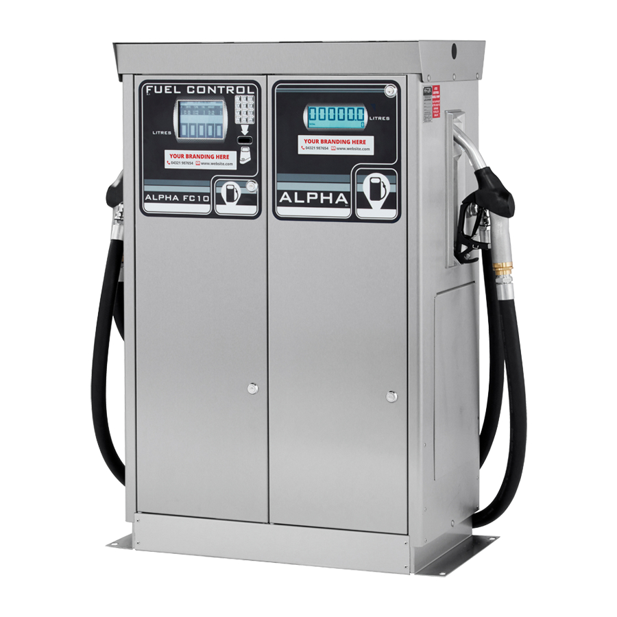
- Page 17 USING THE FC10 FUEL CONTROL UNIT ALPHA PUMP TERMINAL FEATURES The Alpha Pump Terminal, pictured below is fitted into the front of the Alpha fuel dispenser. FEATURES: Display: This shows pump totals as well as user information and instructions. The display is backlit to allow the pump to be used in all light conditions.
-
Page 18: Display Information
THE ALPHA PUMP TERMINAL IN STANDBY MODE This is when the Alpha Pump Terminal is powered up, with the display illuminated, but not in use. DISPLAY INFORMATION: Total Pump 1: This is the number shown in the top left-hand corner of the display screen. - Page 19 "PLEASE ENTER DRIVER ID". Type the identity PIN number of the driver, on the keypad, followed by pressing the "ENT" key. e.) If an additional pump is connected to the ALPHA FC10 and all the access protocol entered has been accepted then the display will show “PLEASE SELECT A PUMP……”.
- Page 20 ALPHA ATEX TWIN PARTS LIST PART DESCRIPTION PART NUMBER EXTERNAL COMPONENTS TOP CAP ALP.CAP3T FC10 OR ALPHA LCD DISPLAY UNIT CONTACT HYTEK ALP.NOZBOOT.A OR NOZZLE HOLSTER WITH SWITCH (X2) ALP.NOZBOOT.FC10 OUTLET ELBOW (X2) ELB.4FFCR DOOR (X2) ALP.DOORASS3A OR ALP.DOOR.FC3 DOOR (FRONT NOZZLE OPTION)* (X2) ALP.DOORASS.F3A...
- Page 21 ALPHA TWIN EXTERNAL VIEW S858/4...
- Page 22 ALPHA TWIN INTERNAL VIEW S858/4...
- Page 23 BLANK PAGE S858/4...
-
Page 24: Declaration Of Conformity
THE INFORMATION CONTAINED IN THIS DOCUMENT IS PROTECTED BY COPYRIGHT © AND PROPERTY LAWS AND IS THE SOLE PROPERTY OF HYTEK (GB) LTD. ANY REPRODUCTION IN PART OR AS A WHOLE WITHOUT THE WRITTEN PERMISSION OF HYTEK (GB) LTD IS PROHIBITED.
Need help?
Do you have a question about the ALPHA and is the answer not in the manual?
Questions and answers