
Related Manuals for Newco Mini-Cappuccino


Summary of Contents for Newco Mini-Cappuccino
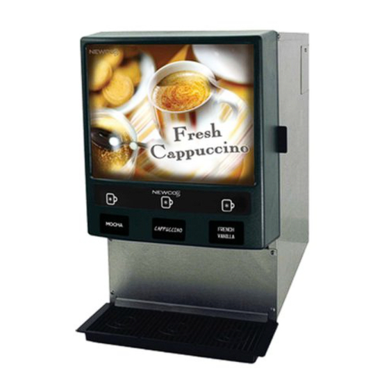
- Page 1 Mini Cappuccino Instruction Manual Features • Under 17” Tall-Fits On Counter Under Cabinets • Programmable Auto Dispense Feature • Auto Rinse Feature • Pump Technology for Precise Liquid Control Date: 03 29 2004...
-
Page 2: Table Of Contents
Unpacking and Start-up………………………..Page 4 Troubleshooting…………………………………Page 6 Product Loading…………………………………Page 7 Machine Operation………………………………Page 8 Cleaning and Sanitizing …………………………Page 10 Service Procedures & Diagrams...………………Page17 Wiring Diagram…………………………………..Page 24 Newco Enterprises, Inc. 3065 New Town Blvd Saint Charles, MO 63301 Telephone 1-800-325-7867 Technical Support 1-800-556-3926 Fax 1-636-925-0029... -
Page 3: Specifications
3 # Mach 17 1/2" 20 1/8" + 4" Legs 24 1/8" 4 25/32" 10 3/4" MODEL MINI CAP-3 SPECIFICATIONS: Shipping Weight: 39 Lbs Body Construction: 300 series Stainless Electrical: 120 VAC 15 A Heater: 1400 W Tank Capacity: 1 US Gallon Products: 3 Canister Size: 2 Lbs * Dispense Mode: Portion or Manual... -
Page 4: Unpacking Instructions
Carefully unpack the Mini Cap-3 Machine and inspect immediately for shipping damage. Your MC-3 Machine was shipped in a carton designed to give it maximum protection in normal handling. It was thoroughly inspected before leaving the factory. In case of damage, contact Newco. INSTALLATION INSTRUCTIONS... - Page 5 Cleaning 1. Remove the drip tray with grill and empty the contents. 2. Wash and let dry the tray and grill (use a mild dishwasher detergent). 3. Wash and let dry the dispense area. 4. Turn the power switch to ON. Flushing the Whipper Chambers (See Illustration of Membrane Switch Page 8 ) 1.
-
Page 6: Troubleshooting
Make sure harness is seated and locked Replace water pump (PN 781690) Adjust temperature setting (see instructions page 9) Reset hi-limit thermostat (Call Newco ) Replace heater element (Call Newco) Check probe connections (see page 21) Check valve and connections-replace if... -
Page 7: Product Loading
Product Loading Instructions Turn Nozzles Up Prior to Removing Product Hoppers Product Hopper Removal: Turn Nozzle UP as illustrated above Grasp Hopper at Nozzle and lift slightly to disengage locating pin Pull Hopper assembly forward and remove from machine The Hoppers hold approximately two pounds of Product. Do not overfill or pack product in canisters. Pour Product into Hoppers in a back and forth motion to evenly distribute the powder, to avoid spilling. -
Page 8: Machine Operation
Machine operation and calibration settings Dispense Membrane Switch Dispense Button (Left) *Note: The Hidden Button has a slight depression in the face of the membrane switch and is centered between Dispense Buttons Two and Three below the 'TM' Portion Control Mode: To initialize the portion control mode perform the following steps: 1. - Page 9 Manual Dispense Mode (Momentary) To cancel Portion Control Mode and return to Manual Mode, follow the Portion Control Instructions-release Hidden Button in step 5 after product dispense starts in less than 5 seconds. When using Manual Mode release the hidden button when cup is approximately 2/3 full or less.
-
Page 10: Cleaning And Sanitizing
Heater Adjustment The Heater is adjustable from a range of 150 F-195F (see illustration page 9) Note: Temperature at dispense point will be slightly lower. Flushing the Mixing Chambers The Mixing Chambers should be sanitized at least once per day. To initialize Sanitation Mode perform the following steps: 1. -
Page 11: Weekly Cleaning
Whipper and Mixing Chamber Disassembly and Cleaning (see Illustration page 5 & 12 ) 1. Remove the Steam Caps by Turning Clockwise to free 2. Remove the Mixing Bowl by lifting the front edge of the bowl until it is free of the Whipper Chamber and pull forward to free the Mixing Bowl water inlet stem free of the Bulkhead Fitting. - Page 12 Mixing/Whipper Chambers Disassembly Steam Cap PN 781568 Mixing Bowl PN 781571 Bulkhead Fitting PN 781040 Slinger Washer PN 781717 Whipper Motor PN 781563 Whipper Chamber PN 781558 Whipper Base PN 781557 Flow Restrictor Shaft Seal PN 781562 PN 781566 Whipper Blade PN 781564...
- Page 13 Product Canister Disassembly and Cleaning (see illustration page 15) With door open turn the Dispense Nozzles facing up (see page 7) 2. Remove the Product Canister and dispenser nozzle. 3. Rotate the front Threaded Retaining wheel counterclockwise and remove 4. Remove the Nozzle Bushing 5.
- Page 14 Product Canister Reassembly (continued) 5. Insert the Nozzle Bushing “facing up” as shown in the diagram 6. Ensure the locating tabs on the seat of the Nozzle Bushing drop into the recesses of the hole in the Canister 7. Screw the read Threaded Retaining ring clockwise locking down the Drive Link Assembly and Auger Spring 8.
- Page 15 Product Canister Disassembly A. Canister Body -PN 781855 B. Elbow-Dispense-PN 781833 C. Nozzle-PN 781584 D. Auger Spring -PN 781835 E. Front Motor Drive-PN 781836 F. Bushing-PN 781838 G. Nut-PN 781839 (2) Note - 3 lb Cannister Ass'y is PN 781864 . 3 lb Cannister body is PN 781582 PN 781857 H.
- Page 16 Steam Tray Removal Steam Tray PN 781649 Door Ass'y PN 781776 Cleaning Brush is PN 111622, Brushholder bracket is PN 104023...
-
Page 17: Service Procedures & Diagrams
Service Procedures Note: Servicing this unit should be done by authorized personel only. Before Servicing unit: 1. Turn Power Switch to Off Position 2. Unplug Power Cord from outlet 3. Disconnect water line (ensure water supply to machine is turned OFF!) 4. -
Page 18: Front Access Panel Removal
Front Access Panel Removal Board Access Panel PN 108014 Heater Leads Heater Indicator Light PN 100667 Front Access Panel Drain Hose Access PN 781576 Area... - Page 19 Sheet Metal Panel Removal Access Screws 2 LB Cover PN 781597 3 LB Cover PN 781851 Back Panel PN 781676 2 LB Legs PN 111377 3 lb 4" Legs PN 100542 Loosen Screws: Note: It is not necessary to completely remove these six screws to remove cover and back panels...
- Page 20 Tank Release Screws Front PN 100425...
- Page 21 Tank Disconnects Prior to Removal Disconnect: 1. Pump Tubes (3) 2. Main Power Connector 3. Float Switch Connector 4. Thermistor 5. Relay Connector 6. Pump Connector 7. Probe Connector 8. Water Line...
-
Page 22: Tank Assembly
Float Switch PN 781694 Heater Relay 12 vdc PN 110958 Water Pump W/Elbow PN 781772 Tank Assembly PN 781673 Tank Lid Punched PN 781770 Tank Gasket PN 781181 Punched Tank PN 781672 Temperature Thermistor PN 151800 Grommet #102836 Barbed Fitting PN 107329 Heater Element 1400 w... - Page 23 Auger Drive Motor PN 781587 Control Board PN 103401 Inlet Solenoid Valve PN 781782 Water Inlet Liquid Level Probe PN 107077 Grommet #102836 Components Top and Rear Access Transformer 110VAC 12-24 VAC PN 105115 Steam Vent Blower Motor PN 781647 Power Switch PN 100500...
-
Page 24: Wiring Diagram
WATER VOLTAGE LEVEL CIRCUIT PROBE YELLOW BROWN TANK THERMISTOR GROUND PROBE DC MOTOR NOTES NOTE: ALL MOTORS ARE DC. DOT BY YELLOW MOTOR TERMINAL INDICATES POSITIVE THE AUGER DRIVE AUGER MOTORS MUST HAVE NEGATIVE WIRE ON DRIVE POSITIVE TERMINALS 1 (LEFT) AND POSITIVE WIRE ON NEGATIVE TERMINALS...
Need help?
Do you have a question about the Mini-Cappuccino and is the answer not in the manual?
Questions and answers