
Related Manuals for Newco Bistro Touch


Summary of Contents for Newco Bistro Touch
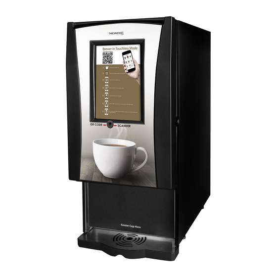
- Page 1 PN. 128142 1-30-2018 Bistro Touch Operating Instruction Manual Model BISTRO-TCH 1-800-325-7867 3650 NEW TOWN BLVD ST. CHARLES MO 63301 WWW.NEWCOCOFFEE.COM 1 ...
-
Page 2: Table Of Contents
Table of Contents Introduction & Newco Product Warranty ....4 Machine Dimensions & Specifications ......5 Machine Features ............6 Plumbing Connections ........... 7 Installation Instructions..........8 Setup Instructions Bistro Touch..……...…....9 Product Installation Procedure........9 Touch Screen Startup Instructions…......12 Machine Startup Instructions ........14... - Page 3 Warning Labels NOTICE: Read and follow all notices posted on this machine. Do not damage or destroy these notices as they are for your protection WARNING DO NOT OVERLOAD CIRCUIT. ALWAYS ELECTRICALLY GROUND THE CHASSIS OR ADAPTOR PLUG. ...
-
Page 4: Introduction & Newco Product Warranty
(800) 556-3926 or by writing to PO Box 852, Saint Charles, MO 63302; 2) if requested by Newco, shipping the defective equipment prepaid to an authorized Newco service location; and 3) receiving prior authorization from Newco that the defective equipment is under warranty. -
Page 5: Machine Dimensions & Specifications
Machine Dimensions & Specifications 120 VAC-1600W HEATER-15A USA POWER SUPPLY 120 VAC-1400W HEATER-15A CANADIAN POWER SUPPLY ½ GALLON TANK 6-8-10-12-16 OZ CUP SIZES 5 LB HOPPERS DRIP TRAY & DRIP TRAY GRATE REGULAR COFFEE CHOCOLATE HOPPER TOUCHSCREEN MILK HOPPER ON/OFF SWITCH RINSE BUTTON DECAF COFFEE WHIPPER CHAMBER ... -
Page 6: Machine Features
Machine Features NO CALIBRATION NEEDED-PLUG & PLAY DECAF BUTTON SWITCHES TO DECAF BIB WHIPPER RINSE BUTTON AUTOMATIC POWDER LEVEL RESET PRE- PROGRAMMED DRINK RECIPES BUTTON ASSIGNMENT FOR RECIPES INDEPENDENT POWDER HOPPER COUNTDOWN &... -
Page 7: Plumbing Connections
Plumbing Connections Plumber’s Installation Instructions CAUTION: Disconnect Power to machine before proceeding with plumbing installation. Attach water line to water filter, rear of machine. Flush water line before installing machine. Machine should be connected to COLD WATER LINE ONLY. - Page 8 Machine Installation Instructions WARNING: - Read and follow installation instructions before plugging or wiring in machine to electrical circuit. Warranty will be void if machine is connected to any voltage other than that specified on the nameplate serial tag. Machine must be on a flat and level surface.
-
Page 9: Product Installation Procedure
Product Installation Procedure Open product box and remove the BIB product, Fig 1. Place in Coffee BIB Tray, Fig. 2, (Newco PN 121929) as shown in Fig. 3. Fig. 3 Fig. 2 Fig. 1 Fig. 4 Remove the plastic insert from the BIB fitment as shown in Figure 4. - Page 10 Product Installation Procedure Cont’d Fig. 5 Using finger and thumb only to prevent over-tightening, thread the BIB connector on to the BIB fitment until seated as shown in Figure 5. Fig. 6 Place the product in the storage compartment as shown in Figure 6.
- Page 11 Product Installation Procedure Cont’d Position the tubing as shown in Figure 7-repeat for 2 BIB- NOTE COFFEE BIB IS LH CONNECTOR AND DECAF BIB IS RH CONNECTOR Fig. 7 NOTE: REFER TO “PRIMING” INSTRUCTIONS AFTER FOLLOWING MACHINE STARTUP PROCEDURES 11 ...
-
Page 12: Touch Screen Startup Instructions
Touch Screen Startup Instructions 1 . OPEN DOOR, PRESS AND HOLD ON/OFF BUTTON FOR 10 SECONDS. RELEASE BUTTON WHEN DISPLAY SHOWS STARTUP SCREEN 2 . WAIT 30 SECONDS‐‐ THEN CYCLE POWER SWITCH TO ‘ON’ POSITION. Note: This machine is designed to be run with power cycled on at all times. Refer to the Startup and Power down instructions below and also attached to the inside of the cabinet door for shutting down the Touch Screen Display when the machine is not in use. - Page 13 Touch Screen Shutdown Instructions Note: This machine is designed to be run with power cycled on at all times. Refer to the Startup and Power down instructions below and also attached to the inside of the sidecar door for shutting down the Touch Screen Display when the ...
-
Page 14: Machine Startup Instructions
Machine Startup Instructions Fill and install 2lb hoppers with nozzles turned up, Chocolate on left and Milk on right. Make sure “button” on bottom of hopper is seated in slot in sheet metal. Slight manual rotation of the auger gear may be necessary to seat hopper in correct location. Rotate dispense nozzles down into whipper bowl. - Page 15 Brewing Drinks To dispense a drink, place a cup under the dispense area, press a brew selection Once a selection is made a Submenu for Drink Settings will appear-see page 13 ICED COFFEE IS SIZED FOR CUP TO Coffee Drinks Small –...
- Page 16 Drinks Submenu Cup Size Coffee Strength Indicator Indicator Cup Strength Selections Cup Size Selections Mild –Regular- Bold Small –Medium- Large Use to Change Use to Change Coffee Strength Cup Size Default Regular Default 8-10-12 Return Button Brew Button ...
-
Page 17: Programming Instructions
be shown on “Call for Drink Selection Menu‐See Service “ Screens Below Restore Factory Settings Exit Setup Mode Total run cycles‐Total drinks Water Filter Remaining Gal* Primary Newco Server dispensed *NOT SHOWN IF NOT USING (Future Use) Secondary A WATER FILTER Water filter Reset‐‐Select Pod brew cycles—Tea & Coffee Server (Future drinks dispensed this after changing filters to Use) reset water filter ... -
Page 18: Custom Logo Setup
Custom Logo--Wifi Setup TURN ON POWER TO MACHINE SETTING UP A CUSTOM LOGO SCREEN USING SWITCH AT LOWER LEFT REQUIRES A WIFI CONNECTION TO THE BISTRO REAR OF MACHINE TOUCH MACH INE. NOTE THAT AFTER THE LOGO IS INSTALLED, THE WIFI CONNECTION NEEDS TO BE TURNED BACK TO “OFF” STATUS 1. TOUCH TO ACCESS 2. ... - Page 19 INSTALL CUSTOM LOGO TAP 3 TIMES TO ENTER PROGRAMMING MODE ‐‐IF A BREWING ICON IS THIS ADDRESS IS UNIQUE FOR EVERY ACCIDENTLY TOUCHED USE THE RETURN MACHINE. NOTE THAT IT IS USED FOR ARROW TO TRY AGAIN THE HOST ADDRESS WHEN SETTING UP COMMUNICATION SITE Install Logo Instructions-Custom Sleep Screen 1. ...
- Page 20 Install Logo Instructions-Custom Sleep Screen (IOS Apple Version) 1. OPEN THE APP AND SLELCT FTP/FTPS/ SFTH, ADD SERVER, INSTALL THE “ITRANSFER” APP ONTO A LOCAL PHONE OR TABLET. CONNECT THE LOCAL PHONE OR TABLET TO THE SAME WIFI NETWORK AS THE BISTRO‐TOUCH. APPLICATION EXAMPLE SHOWN IS “ITRANSFER” FOR I‐PHONE/IOS/APPLE SETUP FTP CONNECTION AS SHOWN‐COPY HOST ADDRESS FROM BISTRO‐TOUCH AS SHOWN ON SCREEN‐ NOTE‐EACH MACHINE HAS A UNIQUE ADDRESS ...
- Page 21 Install Logo Instructions-Custom Sleep Screen (IOS Apple Version) Cont’d 7. STATUS ON BISTRO‐TOUCH 8. TO SELECT A FILE TO TRANSFER 9. SELECT THE DIRECTORY WHERE MACHINE CHANGES TO SELECT THE UPLOAD BUTTON THE IMAGE FILE TO BE Connected‐Waiting for transfer TRANSFERRED RESIDES 10. SELECT THE IMAGE TO BE 11. FILE WILL TRANSFER TO THE 12. SELECT FINISH TO COMPLETE TRANSFER, THEN BISTRO‐ TRANSFERRED THEN SELECT EXIT FROM PROGRAMMING SCREENS. TURN OFF TOUCH MACHINE Upload WIFI, SEE BELOW. FINISH Turning off WIFI Mode TURN ON POWER TO MACHINE USING SWITCH AT LOWER LEFT REAR OF MACHINE OPEN ICONS, SETTINGS, WIFI. TURN WIFI SWITCH OFF & THEN POWER DOWN TOUCHSCREEN—SEE INSTRUCTIONS ...
- Page 22 Load Software Update Future updates to the Touch Screen Software will be delivered via e-mail. Instructions for updating the firmware from a Smart Phone or Tablet will be included in the e-mail. TROUBLESHOOTING SCREENS These error screens will display a service phone number to call if entered in “Setup” Menu (Page 15) *Usually repairing a bad connection or replacing the indicated motor will remedy the problem.
-
Page 23: Whipper Disassembly
Whipper Disassembly 767376 WHIPPER STEAM CAP 767195 WHIPPER MOTOR 767196 BASE, WHIPPER MOUNTING 767197 WHIPPER IMPELLER 767365 WHIPPER BOWL 767200 WHIPPER NOZZLE 781566 WHIPPER SEAL (REPLACE AFTER 2500 CYCLES) 23 ... -
Page 24: Cleaning & Sanitizing Instructions
Cleaning & Sanitizing Instructions Fig. 1 Fig. 2 1. Remove product from storage area and disconnect BIB connectors as shown in figures 1 & 2. 24 ... - Page 25 Cleaning & Sanitizing Instructions-Cont’d Fig. 3 2. Place an empty container in the dispense area of the machine as shown in figure 3. *NOTE: MODEL B-10 SHOWN-MODEL B-10 T AND BISTRO TOUCH HAVE 2 CONNECTORS. 25 ...
- Page 26 Cleaning & Sanitizing Instructions-Cont’d Fig. 4 Fig. 5 3. Connect the sanitizing solution adaptor (PN 120513) to the BIB connector for Pump and connect sanitizing BIB (PN 120509) as shown in figures 4 & 5. 26 ...
- Page 27 Sanitizing Instructions 1. Remove the product BIBs from the machine and connect a BIB of sanitizing solution to the PUMP 1 BIB connector as shown in figs. 1-4 pages 22-24 2. Enter “Programming Mode” (See Page 17) 3. Enter ‘Maintenance” Mode. 4.
- Page 28 Weekly Cleaning Instructions 1. Following cleaning instructions above page 27. 2. Remove the bag connector from the product box and disassemble or prop open the internal valve to allow free flow of product through the connector. NOTE: Cutting the mating fittings from an empty bag makes an excellent “free flowing”...
- Page 29 29 ...
-
Page 30: Service Notes
Service Notes This machine uses advanced diagnostics to alert the operator should any of the motors or motor controllers sense the motors are not turning at the correct rate or sense a bad connection. These errors highlighted by a scrolling display such as “Call for Service— (Left Auger) Motor Error”, and the Service Number entered during machine set-up will be displayed. -
Page 31: Wiring Diagram
WIRING DIAGRAM w 31 ...
Need help?
Do you have a question about the Bistro Touch and is the answer not in the manual?
Questions and answers