Table of Contents
Advertisement
Available languages
Available languages
Quick Links
NATURAL GAS MODELS:
PROPANE GAS MODELS:
SAFETY INFORMATION
WARNING
!
FIRE OR EXPLOSION HAZARD
Failure to follow safety warnings exactly
could result in serious injury, death, or
property damage.
- Do not store or use gasoline or other
fl ammable vapors and liquids in the vicinity of
this or any other appliance.
- WHAT TO DO IF YOU SMELL GAS:
•
Do not try to light any appliance.
•
Do not touch any electrical switch; do not
use any phone in your building.
•
Immediately call your gas supplier from a
neighbour's phone. Follow the gas
supplier's instructions.
•
If you cannot reach your gas supplier, call
the fi re department.
- Installation and service must be
performed by a qualifi ed installer, service
agency, or the supplier.
This appliance may be installed in an aftermarket,
permanently located, manufactured home (USA
only) or mobile home, where not prohibited by
local codes.
This appliance is only for use with the type of gas
indicated on the rating plate. This appliance is
not convertible for use with other gases, unless
a certifi ed kit is used.
INSTALLER:
Leave this manual with the appliance
CONSUMER:
Retain this manual for future reference
Wolf Steel Ltd., 24 Napoleon Rd., Barrie, ON, L4M 0G8 Canada / 103 Miller Drive, Crittenden, Kentucky, USA, 41030
$10.00
ADD PRODUCT CODE HERE (TRADE GOTHIC LT STD FONT)
HDX35NT
HDX35PT
Phone 1 (866) 820-8686 • www.napoleon.com • hearth@napoleon.com
INSTALLATION AND
ADD MANUAL TITLE
OPERATION MANUAL
CERTIFIED TO THE CANADIAN AND AMERICAN NATIONAL STANDARDS:
CSA 2.22 AND ANSI Z21.50 FOR VENTED DECORATIVE GAS APPLIANCES
IF INSTALLATION + OPERATION, ADD SERIAL
CSA /
INTERTEK
BARCODE LABEL ON THE OWNER'S MANUAL"
LOGO
Product Name / Code
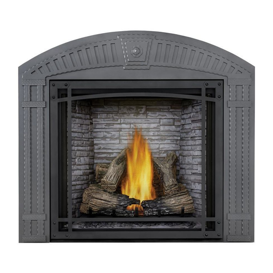
STARfire™ Series
(MUST use title from Price Book)
ADD ____ ILLUSTRATED
ADD PRODUCT IMAGE
FOR INDOOR USE ONLY
NUMBER LABEL HERE
IF SEPARATE MANUALS, ADD "PLACE
ENGLISH
FRENCH PG. 65
HDX35 Illustrated
W415-2372 / B / 12.09.20
Advertisement
Chapters
Table of Contents

Subscribe to Our Youtube Channel
Related Manuals for Napoleon STARfire Series


Summary of Contents for Napoleon STARfire Series
- Page 1 INTERTEK BARCODE LABEL ON THE OWNER’S MANUAL” LOGO Wolf Steel Ltd., 24 Napoleon Rd., Barrie, ON, L4M 0G8 Canada / 103 Miller Drive, Crittenden, Kentucky, USA, 41030 Phone 1 (866) 820-8686 • www.napoleon.com • hearth@napoleon.com $10.00 W415-2372 / B / 12.09.20...
- Page 2 safety information WARNING DANGER • This appliance is hot when operated and can cause severe burns if contacted. • Any changes or alterations to this appliance or its controls can be dangerous and is prohibited. HOT GLASS WILL CAUSE • Do not operate appliance before reading and BURNS.
- Page 3 patterns. RAAK HET GLAS NIET AAN TOT HET IS AFGEKOELD. DUTCH safety information LAAT KINDEREN NOOIT HET GLAS AANRAKEN. WARNING Dit apparaat is voorzien van een barrière die is ontworpen om het risico van brandwonden door het hete kijkglas te beperken. Deze barrière moet worden geïnstalleerd ter bescherming van kinderen •...
-
Page 4: Table Of Contents
table of contents general information operation rates and efficiencies general transmitter layout rating plate information initializing the transmitter/battery holder mobile home installation for the first time dimensions temperature display venting smart thermostat typical vent installation room temperature vent terminal clearances flame height vent application flow chart night light dimmer control... -
Page 5: General Information
standard checklist Installer, please fill out the following information: Customer: ________________________________________________________________________ Address: ________________________________________________________________________ Date of Installation: ________________________________________________________________________ Location of Appliance: ________________________________________________________________________ Installer: ________________________________________________________________________ Dealer/Distributor contact number: ________________________________________________________________________ Serial #: ________________________________________________________________________ Model: Natural Gas: HDX35NT Propane: HDX35PT 1.0 general information This appliance is approved for bathroom, bedroom and bed-sitting room installations and is certified for mobile home installation. - Page 6 general information WARNING • Always light the pilot - whether for the first time or if the gas supply has run out - with the glass door opened or removed. • Provide adequate clearance for servicing and operating the appliance. •...
-
Page 7: Rating Plate Information
Recessed depth X” Profondeur d’encastré une face X” L’appareil doit être ventilé à l’aide de l’ensemble d’évacuation propre à Napoleon. Référez au *** Mantel X” from appliance opening *** Tablette X” de l’ouverture de l’appareil manuel d’installation pour les spécifications d’évacuation. Il est nécessaire de bien réinstaller et *** Maximum horizontal extension: *** L’extension horizontale maximale: X”. -
Page 8: Dimensions
general information dimensions W415-2372 / B / 12.09.20... -
Page 9: Venting
2.0 venting WARNING • Risk of fi re. Maintain specifi ed air space clearances to vent pipe and appliance. • The vent system must be supported every 3’(0.9m) for both vertical and horizontal runs. Use support ring assembly W010- 0067 or equivalent non-combustible strapping to maintain the minimum clearance to combustibles for both vertical and horizontal runs. -
Page 10: Typical Vent Installation
The air terminal must remain unobstructed at all times. Examine the air terminal at least once a year to verify that it is unobstructed and undamaged. Rigid and fl exible venting systems must not be combined. Different venting manufacturer components must not venting be combined. -
Page 11: Vent Terminal Clearances
venting vent terminal clearances Covered balcony applications ††* ≤ 15 feet = 3 feet = 2 x ACTUAL (0.9m) (4.6m) note: INSTALLATIONS Wall terminals are for illustration purposes only. Size and shapes may vary. CANADA U.S.A. 12” (30.5cm) 12” (30.5cm) Clearance above grade, veranda porch, deck or balcony. -
Page 12: Vent Application Flow Chart
venting vent application flow chart Top Exit Horizontal Termination Vertical Termination Vertical rise is equal Vertical rise is equal Vertical rise is less Vertical rise is less to or greater than the to or greater than the than horizontal run than horizontal run horizontal run horizontal run... -
Page 13: Horizontal Termination
venting horizontal termination ) < (V Simple venting configuration (only one 90° elbow) See graph to determine the required vertical rise V for the required horizontal run H 40 (12.2) 39 (11.9) REQUIRED 30 (9.1) VERTICAL RISE IN FEET 20 (6.1) (METERS)V 10 (3.1) 14"... - Page 14 venting ) > (V See graph to determine the required vertical rise V for the Simple venting configuration (only one 90° elbow) required horizontal run H 150 (3810) (3733.8) REQUIRED VERTICAL RISE 100 (2540) IN INCHES (MILLIMETERS) 57 (1447.8) 50 (1270) 19 1/2 14"...
-
Page 15: Vertical Termination
venting vertical termination ) < (V Simple venting configurations. See graph to determine the required vertical rise V for the required horizontal run H 40 (12.2) 30 (9.1) REQUIRED VERTICAL RISE IN FEET 20 (6.1) (METERS) V 10 (3.1) 3 (0.9) (1.5) (3.1) (4.6) - Page 16 venting ) > (V Simple venting configurations. See graph to determine the required vertical rise V for the required horizontal run H 20 (6.1) 19 (5.8) REQUIRED VERTICAL RISE IN FEET 10 (3.1) (METERS) V 3 (0.9) 14" (356mm) (7.6) (9.1) (1.5) (3.1)
-
Page 17: Installation
3.0 installation WARNING • Ensure to unpack all loose materials from inside the fi rebox prior to connecting the gas and electrical supply • If your appliance is supplied with a remote, ensure the remote receiver is in the “OFF” position prior to connecting the gas and electrical supply to the appliance. -
Page 18: Horizontal Installation
installation horizontal installation WARNING • The fi restop assembly must be installed with the vent shield to the top. • Terminals must not be recessed into a wall or siding more than the depth of the return fl ange of the mounting plate. -
Page 19: Vertical Installation
installation vertical installation This application occurs when venting through a roof. Installation kits for various roof pitches are available from your authorized dealer / distributor. See the “accessories” section to order specifi c kits required. A. Determine the air terminal location, cut and frame a square opening, as illustrated, in the ceiling and the roof to provide the minimum 1"... -
Page 20: Using Flexible Vent Components
installation using flexible vent components WARNING • Do not allow the inner fl ex pipe to bunch up on horizontal or vertical runs and elbows. Keep it pulled tight. • Spacers are attached to the inner fl ex pipe at predetermined intervals to maintain an even air gap to the outer fl ex pipe. -
Page 21: Vertical Air Terminal Installation
installation vertical air terminal installation WARNING • Maintain a minimum 2” (51mm) space between the air inlet base and the storm collar. note: Fastening hardware provided with appropriate roof terminal and liner kits. Fasten the roof support to the roof using 6 screws. The roof support is optional. -
Page 22: Appliance Vent Connection
installation ADD FASTENER TYPE appliance vent connection REAR VENT TOP VENT - FLEX TOP VENT - RIGID/FLEX INSERT A. Install the inner fl ex pipe to the appliance. Secure with a minimum of three screws when installing 3”/5”, 4”/7” or 5”/8” venting, or six screws #8 X 1/ #8 X 1/2”... -
Page 23: Framing
4.0 framing note: When using optional fi nishing accessories, the framing dimensions and fi nishing materials may differ from what is outlined in the section below; refer to the leafl et instructions supplied in the accessory kit for specifi c framing and fi nishing specifi cations. - Page 24 framing * When constructing the enclosure allow for finishing material thickness to maintain clearances. important: Before finishing in the appliance test the operation using the remote control, cycling it through all of its different modes, see “OPERATION” section. Should trouble shooting be required, access to the controls can be made through the pre-finishing access panel.
- Page 25 framing 1" CORNER CHASE [25mm] SIDE WALL INSIDE CHASE 6" [152mm] 48" [1219mm] 19 7/8" [505mm] 43 7/8" [1114mm] 19 7/8" [505mm] OUTSIDE CHASE W415-2372 / B / 12.09.20...
-
Page 26: Installing Non-Combustible Board
framing installing non-combustible board WARNING • A non-combustible finishing material border such as brick, marble, granite, etc. is required. Finishing with just non-combustible board to the side and top of the appliance is not recommended. • The surface above the appliance gets very hot. If proper finishing materials are not used, cracking can occur. With the frame assembly in place, use drywall screws to install the non-combustible board sides (1) and center (2). - Page 27 framing Depending on finishing material thickness, the frame assembly can be adjusted out from the appliance by 1 1/2" (38mm), as shown below: note: Framing dimensions will vary depending on finishing material thickness. For recessed depths greater than 2” (51mm), refer to “non-combustible finishing material” section. SIDE VIEW 1 1/2"...
-
Page 28: Minimum Clearance To Combustible
framing minimum clearance to combustible enclosures WARNING • Risk of fire! • The front of the appliance must be finished with any non-combustible materials such as brick, marble, granite, etc. provided that these materials do not cover the appliance opening. important: The HDX35 requires a minimum inside enclosure height of 70”... -
Page 29: Clearance To Combustible Enclosure Without Alcove
framing 4.2.1 clearance to combustible enclosure without alcove 2" 51mm 0” IF NON-COMBUSTIBLE FINISHING MATERIAL IS USED SUCH AS BRICK AND STONE. INSULATED STEEL STUD SLEEVE FRAMING NON-COMBUSTIBLE 1" * MATERIAL 25mm 56 3/4" FIRESTOP 10" 1441mm ASSEMBLY 254mm CEILING 70"... -
Page 30: Alcove Clearance To Combustible
framing 4.2.2 alcove clearance to combustible enclosure note: When framing with an alcove, the enclosure height must be 72” (1829mm), not 70” (1778mm). 2" 51mm 0” IF NON-COMBUSTIBLE FINISHING MATERIAL INSULATED IS USED SUCH AS COMBUSTIBLE SLEEVE BRICK AND STONE. STEEL STUD 6"... -
Page 31: Minimum Combustible Mantel
framing minimum combustible mantel clearances WARNING • Risk of fi re. Maintain all specifi ed air space clearances to combustibles. Failure to comply with these instructions may cause a fi re or cause the appliance to overheat. Ensure all clearances (i.e. back, side, top, vent, mantel, front, etc.) are clearly maintained. -
Page 32: Non-Combustible Finishing Material
framing non-combustible finishing material WARNING: The appliance opening may be recessed in non-combustible facing material provided it does not project more than 2" (50.8mm) past the face of the appliance. If greater projections are desired, increase the clearance to the sides, bottom and top by 2" (50.8mm) for every additional 1" (25.4mm) of projection. If using an optional surround, then 2"... -
Page 33: Finishing
5.0 finishing WARNING • Risk of fi re! • Never obstruct the front opening of the appliance. • The front of the appliance must be fi nished with any non-combustible materials such as brick, marble, granite, etc., provided that these materials do not go below the specifi ed dimension, as illustrated. •... -
Page 34: Latch Door Removal / Installation
finishing latch door removal / installation There are 4 spring latches securing the main glass door, 2 of those latches are across the top and 2 along the bottom. To access these latches ensure the screen is removed. Using the tool provided, pull the latch forward and upwards / downwards, out of the slot in the door, as shown. -
Page 35: Glass Door Removal / Installation
finishing glass door removal / installation Release the 4 door latches from the top and bottom of the door. Refer to ‘LATCH DOOR REMOVAL / INSTALLATION’ section. Slide the glass door forward from the appliance. It will sit on the door slides attached to the appliance, refer to Figure 1. -
Page 36: Burner Installation
finishing burner installation See instructions accompanying burner assembly (sold separately). logo placement SAFETY BARRIER LOGO W415-2372 / B / 12.09.20... -
Page 37: Electrical Information
6.0 electrical information WARNING • Ensure to unpack all loose materials from inside the fi rebox prior to connecting the gas and electrical supply • If your appliance is supplied with a remote, ensure the remote receiver is in the “OFF” position prior to connecting the gas and electrical supply to the appliance. -
Page 38: Battery Holder Installation
electrical information battery holder installation The battery holder must be located within 8 feet of this side of the appliance and must be accessible for programming the remote. Install 4 AA batteries, ensure that the positive and negative ends correspond with those identified in the battery holder. -
Page 39: Wiring Diagram
electrical information wiring diagram WARNING • Do not wire 110 volts to the valve or wall switch. 43.3A W415-2372 / B / 12.09.20... -
Page 40: Operation
7.0 operation general transmitter layout Key Lock Low battery alarm Transmission Room Temperature CPI mode Flame ON Light Blower (NOT AVAILABLE WITH THIS MODEL) initializing the transmitter/battery holder for the first time Install the 4 AA batteries into the Proflame 2 battery holder, note the polarity of the batteries and insert as indicated on the cover (+/-). -
Page 41: Temperature Display
Temperature Key Mode Key Up / Down Arrow Key Up / Down Arrow Key Mode Key Up / Down Arrow Key Room Temperature Room Temperature Mode Key Mode Key Mode Key Up / Down Arrow Key Mode Key ADD TITLE: ROOM THERMOSTAT Room Temperature °F °F... -
Page 42: Continuous Pilot/Intermittent Pilot (Cpi/Ipi) Selection
OFF ON A. Use the Mode Key to guide you to the Night Light icon. Temperature Key B. Pressing the Up Arrow Key will activate the NIGHT LIGHT™. °F °F °F °F Up / Down Arrow Key B. The intensity of the output can be adjusted through 6 levels. SMART C. -
Page 43: Operation
8.0 operation operation WARNING • If you do not follow these instructions exactly, a fi re or explosion may result causing property damage, personal injury, or loss of life. • If applicable, always light the pilot whether for the fi rst time or if the gas supply has run out with the glass door opened or removed. -
Page 44: Pilot-On-Demand
In order to start your pilot, turning the main burner on with the switch, remote or thermostat and then turning it off will reactivate the continuous pilot mode and reset the seven day timer. For further information, refer to www.napoleon.com/pilotondemand. 31.2A... -
Page 45: Adjustments
9.0 adjustments operation restricting vertical vents Vertical installations may display a very active fl ame. If this appearance is not desirable, the vent exit must be restricted using a restrictor vent kit. Refer to the “replacement parts” section of the owner’s manual for the appropriate kit. -
Page 46: Venturi Adjustment
adjustments venturi adjustment This appliance has an air shutter that has been factory set open according to the chart below: VENTURI Regardless of venturi orientation, closing the air shutter will cause a more BURNER yellow flame, but can lead to carbonization. Opening the air shutter will cause a more blue flame, but can cause flame lifting from the burner ports. -
Page 47: Maintenance
10.0 maintenance WARNING • Turn off the gas and electrical power before servicing the appliance. • Appliance may be hot. Do not service until appliance has cooled. • Do not use abrasive cleaners on glass. • Do not paint the pilot assembly. This appliance and its venting system should be inspected before use and at least annually by a qualifi ed service person. -
Page 48: Annual Maintenance
maintenance 10.1 annual maintenance WARNING • Annual maintenance should be performed by a qualifi ed service technician • The fi rebox becomes very hot during operation. Let the appliance cool completely or wear heat resistant gloves before conducting service. • Never vacuum hot embers. -
Page 49: Control Access
maintenance 10.2 control access Once the appliance has been framed and finished, control access can only be achieved by removing the access panel from the inside right side of the firebox. The following sub sections take you through the steps of accessing the control as if the appliance is installed. -
Page 50: Burner Removal
maintenance 10.3 burner removal Remove any media and/or media tray from the applaince, refer to “MEDIA TRAY REMOVAL” section. Remove the screws from the burner assembly base and carefully lift from the firebox. 10.4 brick panel removal Remove the 2 screws securing the brick panel brackets from the top left of the appliance. Remove the screws securing the front brick retainers. -
Page 51: Night Light™ Replacement
maintenance 10.7 night light™ replacement Your HDX35 comes equipped with a “Night Lights™”. The light has been pre-wired and is controlled from the remote control. If in the event the lamps or lens need replacing, follow the instructions below: A. Shut off breaker at main power supply B. -
Page 52: Glass / Door Replacement
maintenance 10.8 glass / door replacement WARNING • Do not use substitute materials. • Glass may be hot. Do not touch glass until cooled. • Care must be taken when removing and disposing of any broken door glass or damaged components. Be sure to vacuum up any broken glass from inside appliance before operation. -
Page 53: Replacement Parts
11.0 replacement parts WARNING • Failure to position the parts in accordance with this manual or failure to use only parts specifi cally approved with this appliance may result in property damage or personal injury. Contact your dealer for questions concerning prices and policies on replacement parts. Normally, all parts can be ordered through your Authorized dealer / distributor. -
Page 54: Overview
replacement parts W415-2372 / B / 12.09.20... -
Page 55: Valve Train Assembly
replacement parts W415-2372 / B / 12.09.20... -
Page 56: Log Burner
replacement parts W415-2372 / B / 12.09.20... -
Page 57: Glass Burner
replacement parts W415-2372 / B / 12.09.20... -
Page 58: Accessories
12.0 accessories W415-2372 / B / 12.09.20... -
Page 59: Troubleshooting
13.0 troubleshooting WARNING • Always light the pilot whether for the fi rst time or if the gas supply has run out, with the glass door open or removed. • Turn off gas and electrical power before servicing the appliance. •... - Page 60 Check that venting is installed correctly. appliances). Room is in negative pressure; increase fresh air supply. troubleshooting symptom problem test solution Pilot will not light. Makes Wiring: short, loose, or damaged Verify the thermocouple/sensor is clean and the wiring is undamaged. Verify the interrupter block is not damaged or too tight.
- Page 61 Wire connector pins are bent. Straighten pins. Wire connector pins are bent. Straighten pins. symptom problem test solution Valve wiring is damaged. Replace valve. Valve wiring is damaged. Replace valve. troubleshooting Lights or blower Control module switch in Verify ON/OFF switch is in the “I” position which denotes on. won’t function (if wrong position.
-
Page 62: Warranty
Napoleon neither assumes, nor authorizes any third party to assume, on its behalf, any other liabilities with respect to the sale of this product. Napoleon will not be responsible for: over- fi ring, downdrafts, spillage caused by environmental conditions such as rooftops, buildings, nearby trees, hills, mountains, inadequate vents or ventilation, excessive venting confi gurations, insuffi cient makeup air, or negative air pressures which may or may not be caused by mechanical systems such as exhaust fans, furnaces, clothes dryers, etc. - Page 63 notes 29.1 W415-2372 / B / 12.09.20...
- Page 64 NAPOLEON CELEBRATING OVER 40 YEARS OF HOME COMFORT PRODUCTS 7200, Route Transcanadienne, Montréal, Québec H4T 1A3 24 Napoleon Road, Barrie, Ontario, Canada L4M 0G8 214 Bayview Drive, Barrie, Ontario, Canada L4N 4Y8 103 Miller Drive, Crittenden, Kentucky, USA 41030 De Riemsdijk 22, 4004 LC Tiel, The Netherlands Phone: 1-866-820-8686 napoleon.com...
- Page 65 IF SEPARATE MANUALS, ADD “PLACE LOGO BARCODE LABEL ON THE OWNER’S MANUAL” Wolf Steel Ltd., 24 Napoleon Rd., Barrie, ON, L4M 0G8 Canada / 103 Miller Drive, Crittenden, Kentucky, USA, 41030 Téléphone 1(866)820-8686 • www.napoleon.com • hearth@napoleon.com SERIENNUMMER VOM KARTON AUFBRINGEN $10.00...
- Page 66 NEVER ALLOW CHILDREN TO TOUCH GLASS. A barrier designed to reduce the risk of burns from the hot consignes de sécurité viewing glass is provided with this appliance and must be installed for the protection of children and other at-risk AVERTISSEMENT individuals.
- Page 67 continue de s’éteindre, faire réparer. Garder propres le brûleur et le compartiment de contrôle. • Cet appareil ne devra être modifi é en aucun cas. • Ne laissez pas les ventilateurs souffl er directement sur l’appareil. Empêchez les courants d’air de modifi er consignes de sécurité...
- Page 68 table de matières information générale installation du brûleur taux et efficacités mise en place du logo information à propos de la plaque information électrique d’homologation branchement par câble installation dans une maison mobile 71 schéma de câblage du réceptacle dimensions installation du récepteur évacuation schéma de câblage...
-
Page 69: Information Générale
liste de vérification Installateur, veuillez rempli les informations suivants: Client: ________________________________________________________________________ Adresse: ________________________________________________________________________ Date d'Installation: ________________________________________________________________________ Location de l'Appareil: ________________________________________________________________________ Installateur: ________________________________________________________________________ Numéro de Contact du Détaillant / Distributeur: ________________________________________________________________________ # de Série: ________________________________________________________________________ Modèle: Gaz Naturel: HDX35NT Propane: HDX35PT 1.0 information générale Cet appareil est approuvé... - Page 70 information générale AVERTISSEMENT • Allumez toujours la veilleuse, que ce soit pour la première fois ou lorsque l’approvisionnement en gaz est épuisé, avec la porte vitrée ouverte ou retirée. • Prévoyez un accès suffisant pour entretenir et opérer l’appareil. Assurez-vous d’une quantité suffisante d’air de ventilation.
-
Page 71: Information À Propos De La Plaque
Recessed depth X” Profondeur d’encastré une face X” L’appareil doit être ventilé à l’aide de l’ensemble d’évacuation propre à Napoleon. Référez au *** Mantel X” from appliance opening *** Tablette X” de l’ouverture de l’appareil manuel d’installation pour les spécifications d’évacuation. Il est nécessaire de bien réinstaller et *** Maximum horizontal extension: *** L’extension horizontale maximale: X”. - Page 72 information générale dimensions W415-2372 / B / 12.09.20...
-
Page 73: Évacuation
2.0 évacuation AVERTISSEMENT • Risque d’incendie. Conservez les dégagements nécessaires au conduit d’évent et à l’appareil. • Les courses horizontales et verticales du système doivent être supportées à tous les 3 pi (0,9m). Utilisez l’ensemble de support mural Wolf Steel W010-0067 ou des attaches incombustibles équivalents afi n de maintenir le dégagement aux matériaux combustibles pour les courses verticales et horizontales. -
Page 74: Installation Typique D'évents
This template must be used in conjunction with templates 7.1.1 or 7.1.2, depending on termination shape (i.e. round, or round and square). See appropriate templates folder. évacuation Pour une performance optimale de l’appareil et une apparence optimale des fl ammes, gardez la longueur des évents et le nombre de coudes au minimum. -
Page 75: Emplacement Et Dégagements
évacuation emplacement et dégagements minimaux de la terminaison Applications pour balcon couvert ††* = 3 feet ≤ 15 feet = 2 x ACTUAL (0.9m) (4.6m) note: INSTALLATIONS Les terminaux du mur sont à des fi ns d’illustration seulement. La taille et les formes peuvent varier. CANADA É.-U. -
Page 76: Charte D'application Des Évacuations
évacuation charte d’application des évacuations Évacuation sur le dessus Terminaison horizontale Terminaison verticale La course verticale La course verticale La course verticale est La course verticale plus grande ou égale à est plus petite que la est plus grande ou est plus petite que la la course horizontale course horizontale... -
Page 77: Terminaison Horizontale
évacuation terminaison horizontale ) < (V Configuration d'évacuation simple (un coude de 90° Consultez le graphique pour déterminer la course verticale seulement). nécessaire V par rapport à la course horizontale requise H 40 (12,2) 39 (11,9) COURSE 30 (9,1) VERTICALE REQUISE EN 20 (6,1) PIEDS... - Page 78 évacuation ) > (V Consultez le graphique pour déterminer la course verticale Configuration d'évacuation simple (un coude de 90° nécessaire V par rapport à la course horizontale requise H seulement). 150 (3810) 150 (3810) 147 (3733.8) 147 (3733.8) COURSE 100 (2540) 100 (2540) VERTICALE REQUISE EN...
-
Page 79: Termination Verticale
évacuation termination verticale ) < (V Configuration d'évacuation simple. Consultez le graphique pour déterminer la course verticale nécessaire V par rapport à la course horizontale requise H 40 (12,2) 30 (9,1) COURSE VERTICALE REQUISE EN 20 (6,1) PIEDS (MÈTRES)V 10 (3,1) 3 (0,9) (1,5) (3,1) - Page 80 évacuation ) > (V Configuration d'évacuation simple. Consultez le graphique pour déterminer la course verticale nécessaire V par rapport à la course horizontale requise H 20 (6,1) 19 (5,8) COURSE VERTICALE REQUISE EN 10 (3,1) PIEDS (MÈTRES) V 3 (0,9) 2 (0.6) (7,6) (9,1)
-
Page 81: Installation
3.0 installation AVERTISSEMENT • Avant d’effectuer les branchements pour l’alimentation en gaz et électronique, assurez-vous de retirer toute composante non fi xée à l’intérieur de la chambre de combustion. • Si votre appareil comprend un système de télécommande, assurez-vous que le récepteur est à la position «... -
Page 82: Installation Horizontale
installation installation horizontale AVERTISSEMENT • L’espaceur coupe-feu doit être installé avec l’écran protecteur orienté vers le haut. • La terminaison ne doit pas être enchâssée dans le mur ou le revêtement extérieur plus que l’épaisseur de la bride de la plaque de montage. •... -
Page 83: Installation Verticale
installation installation verticale Cette confi guration s’applique lorsque l’évacuation se fait à travers un toit. Des ensembles d’installation pour les différentes pentes de toit sont disponibles chez votre détaillant autorisé. Voir la section « accessoires » dans le manuel du propriétairepour commander l’ensemble spécifi que dont vous avez besoin. -
Page 84: Utilisation De Composants Flexibles
installation utilisation de composants flexibles d’évacuation AVERTISSEMENT • Ne laissez pas la gaine fl exible se tasser contre les courses horizontales ou verticales et les coudes. Gardez-la tendue. • Des espaceurs sont fi xés à la gaine fl exible à intervalles prédéterminés afi n de garder un espace vide avec le conduit extérieur. -
Page 85: Installation De La Terminaison Verticale
installation installation de la terminaison verticale AVERTISSEMENT • Conservez un espace minimale de 2 po (51mm) entre la base de la prise d’air et le collet de solin. Matériel de fi xation fourni avec les ensembles de terminal pour toit et raccord appropriées. Fixez le support de toit au toit à... -
Page 86: Raccordement Des Évents À
installation raccordement des évents à l’appareil REAR VENT TOP VENT - FLEX TOP VENT - RIGID/FLEX A. Raccordez la gaine fl exible intérieure à l’appareil. Fixez-la à l’aide d’au #8 X 1/2” moins trois vis et rondelles lorsque vous utilisant une évent de 3”/5”, 4”/7” #8 X 1/2”... -
Page 87: Ossature
4.0 ossature note: Lorsque vous installez les accessoires de fi nition optionelles, les dimensions de l’ossature et les matériaux de fi nition peuvent différer de ce qui est décrit dans ces instructions ci-dessous, voir les instructions fournies dans le trousse de l’accessoire pour les spécifi cations détaillées. AVERTISSEMENT •... - Page 88 ossature * Lorsque vous construisez l’enceinte, prévoyez l’épaisseur des matériaux de finition pour maintenir les dégagements. important: Avant d’effectuer la finition, vérifiez le fonctionnement de l’appareil à l’aide de la télécommande en testant chacun des différents modes. Voir la section « FONCTIONNEMENT ». Si un dépannage s’avère nécessaire, l’accès aux contrôles peut se faire par le panneau d’accès de préinstallation.
- Page 89 ossature 1" ENCEINTE EN COIN CORNER CHASE [25mm] SIDE WALL ENCEINTE INSIDE CHASE INTÉRIEURE 6" [152mm] 48" [1219mm] 19 7/8" [505mm] 43 7/8" [1114mm] 19 7/8" [505mm] OUTSIDE CHASE ENCEINTE EXTÉRIEURE W415-2372 / B / 12.09.20...
-
Page 90: Installation Du Matériaux
ossature installation du matériaux incombustible AVERTISSEMENT • Une finition incombustible comme de la brique, du marbre, du granite, etc. est requise. Il est interdit d’utiliser seulement des panneaux de incombustibles pour la finition des côtés et du dessus de l’appareil. •... - Page 91 ossature Selon les matériaux de finition, l’assemblage de châssis peut être réglé à partir de l’unité de 1 1/2 “(38mm), comme indiqué ci-dessous: note: Dimensions d’ossature varient en fonction de l’épaisseur du matériaux de finition. Pour des profondeurs supéri- eures à 2” (51mm), référez à la section « matériau de finition incombustible ». VUE DE CÔTÉ...
- Page 92 ossature dégagements minimaux aux enceintes combustibles AVERTISSEMENT • Risque d’incendie! • La façade du foyer doit être faite de matériaux non combustibles comme de la brique, du marbre, du granite, etc. à condition que ces matériaux ne couvrent pas l’ouverture du foyer. important: Le HDX35 requiert une hauteur d’enceinte minimale de 70”...
-
Page 93: Dégagements Minimaux Aux Enceintes Combustibles Sans Alcôve
ossature 4.2.1 dégagements minimaux aux enceintes combustibles sans alcôve 2" 51mm 0” SI LA FINITION NON 0” IF NON-COMBUSTIBLE COMBUSTIBLE UTILISÉE FINISHING MATERIAL DE LA BRIQUE OU DE LA IS USED SUCH AS PIERRE BRICK AND STONE. INSULATED OSSATURE AVEC MANCHON STEEL STUD D’ISOLANT... -
Page 94: Dégagements Minimaux Aux Enceintes Combustilbes Avec Alcôve
ossature 4.2.2 dégagements minimaux aux enceintes combustilbes avec alcôve note: Lorsque de l’élaboration d’une alcôve, la hauteur de l’enceinte doit être 72” (1829mm), pas 70” (1778mm). 2" 51mm 0” SI LA FINITION NON 0” IF NON-COMBUSTIBLE COMBUSTIBLE UTILISÉE FINISHING MATERIAL DE LA BRIQUE OU DE LA INSULATED MANCHON... -
Page 95: Dégagements Minimaux De La
ossature dégagements minimaux de la tablette AVERTISSEMENT • Rique d’incendie. Conservez tous les dégagements aux matériaux combustibles spécifi és. Incapacité de se conformer à ces instructions peut causer un incendie ou une surchauffe. Assurez-vous que tous les dégagements (arrière, côtés, dessus, évents, tablette, façade, etc.) sont respectés à la lettre. •... -
Page 96: Matériau De Finition Incombustible
ossature matériau de finition incombustible AVERTISSEMENT: L'ouverture de l'appareil peut être encastré dans le matériaux de finition incombustibles à condition ne pas dépasser de plus de 2" (50,8mm) la façade de la porte (sur toutes côtés). Si des projections plus grandes sont requises, augmentez les dégagements des côtés, au dessous et au dessus de 2" (50,8mm) pour chaque pouce (25,4mm) supplémentaire de projection. -
Page 97: Finitions
5.0 finitions AVERTISSEMENT • Risque d’incendie! • N’obstruez jamais l’ouverture sur le devant de l’appareil. • La façade de l’appareil doit être faite de matériaux incombustibles comme de la brique, du marbre, du granite, etc., à condition que ces matériaux ne se trouvent pas en deçà de la dimension spécifi ée tel qu’illustré. Comme alternative, vous pouvez utiliser le panneau de gypse comme fi nition pour votre appareil, voir les illustrations à... -
Page 98: Enlèvement / Installation De Loquet De Porte
finitions enlèvement / installation de loquet de porte Il y a 4 loquets de porte qui obtient la porte, 2 sont à travers le sommet et 2 à travers le sommet. Pour accéder à ces loquets, la porte à 4 pièces doit être enlevée. -
Page 99: Enlèvement / Installation De La Porte
finitions enlèvement / installation de la porte vitrée Déverrouillez les quatre loquets situés dans le haut et le bas de la porte, voir la section “RETRAITS DU LOQUET DE PORTE”. Glissez la porte vitrée vers l’avant. Elle reposera sur les glissières de porte fixées à l’appareil, refer to Figure 1. -
Page 100: Installation Du Brûleur
finitions installation du brûleur Voir les instructions accompagnant l’assemblage du brûleur (vendu séparément). mise en place du logo SAFETY BARRIER BARRIÈRE DE PROTECTION LOGO W415-2372 / B / 12.09.20... -
Page 101: Information Électrique
6.0 information électrique AVERTISSEMENT • Avant d’effectuer les branchements pour l’alimentation en gaz et électronique, assurez-vous de retirer toute composante non fi xée à l’intérieur de la chambre de combustion. • Si votre appareil comprend un système de télécommande, assurez-vous que le récepteur est à la position «... -
Page 102: Installation Du Récepteur
information électrique installation du récepteur 1. Le récepteur doit être situé à une distance maximale de 8 pieds (2,4m) de ce côté de l’appareil et doit être accessible pour programmer la télécommande. 2. Installez 4 piles AA. Assurez-vous que les extremités positives et négatives correspondent avec ceux dans le récepteur. -
Page 103: Schéma De Câblage
information électrique schéma de câblage AVERTISSEMENT • Ne raccordez pas l’interrupteur mural ou la soupape de gaz à l’alimentation électrique (110 volts) 43.3A W415-2372 / B / 12.09.20... -
Page 104: Fonctionnement
7.0 fonctionnement dessin générale de la télécommande Serrure à clé L’alarme de faible pils Transmission Température du salle Mode CPI Flamme Marche Lumière DEL Soufflerie (PAS DISPONIBLE AVEC CE MODÈLE) première initialisation de la télécommande / bloc piles Installez 4 piles AA dans le bloc-piles du Proflame 2, notez la polarité des piles puis insérez-les comme indiqué... -
Page 105: Afficheur De Température
bip unique du récepteur confi rmera la réception de la commande. TOUCHE MODE TOUCHE HAUT/BAS TOUCHE MODE TOUCHE HAUT/BAS TOUCHE HAUT/BAS température de la pièce. TOUCHE MODE TOUCHE HAUT/BAS TOUCHE MODE TOUCHE HAUT/BAS °F TOUCHE MODE TEMPÉRATURE RÉELLE TOUCHE MODE ADD TITLE: THERMOSTAT DE PIÈCE TOUCHE MODE TOUCHE MODE... -
Page 106: La Sélection Pilote Continu/Pilote Intermittente (Cpi/Ipi)
°F °F SMART Appuyez sur la touche fl échée bas pour éteindre la lumière de veille. Un L’intensité de la production peut être ajustée par 6 niveaux. Utiliser les TOUCHE HAUT/BAS °F AFFICHEUR ACL BLEU bip unique confi rmera la réception de la commande. SMART controls en haut/en bas pour ajuster le niveau de puissance. -
Page 107: Opération
8.0 opération AVERTISSEMENT • Si ces instructions ne sont pas suivies à la lettre, un incendie ou une explosion pourraient s’ensuivre, causant des dommages matériels, des blessures corporelles ou des pertes de vie. • Si applicable, allumez toujours la veilleuse, que ce soit pour la première fois ou lorsque l’approvisionnement en gaz est épuisé, avec la porte vitrée ouverte ou retirée. -
Page 108: Veilleuse Sur Demande
Pour démarrer la veilleuse, en allumant le brûleur principal à l’aide de l’interrupteur, de la télécommande ou du thermostat, et ensuite en l’éteignant, réactivera le mode veilleuse permanente et réinitialisera la minuterie de sept jours. Pour plus d’informations, consultez le site www.napoleon.com/pilotondemand. 31.2A W415-2372 / B / 12.09.20... -
Page 109: Réglages
9.0 réglages réglages PILOT ELECTRODE BURNER étranglement des évents verticaux 3/8” - 1/2” (9.5mm - 12.7mm) Certaines confi gurations d’évacuation verticales peuvent avoir une fl amme très active. Si cette apparence n’est FLAME pas désirée, la sortie du conduit d’évacuation doit être réduite en utilisant une plaque de restriction. Pour obtenir SENSOR l’ensemble approprié, voir la section «... -
Page 110: Réglage Du Venturi
réglages réglage du venturi L’ouverture du volet d’air a été préréglée en usine selon le tableau ci-dessous: Indépendamment de l’orientation du venturi, plus le volet est fermé, plus la VENTURI flamme est jaune et aura tendance à causer des dépôts de carbone. Plus le volet est ouvert, plus la flamme est bleue et plus elle a tendance à... -
Page 111: Entretien
10.0 entretien AVERTISSEMENT • Coupez l’alimentation en gaz et l’alimentation électrique avant de procéder à l’entretien de l’appareil. • L’appareil peut être chaud. Attendez qu’il soit refroidi avant d’en faire l’entretien. • N’utilisez pas de produits abrasifs. • Ne peinture pas l’assemblage de la veilleuse. Cet appareil et son système d’évacuation devraient être inspectés avant la première utilisation et au moins une fois l’an par un technicien de service qualifi é. -
Page 112: Entretien Annuel
entretien 10.2 entretien annuel AVERTISSEMENT • Le caisson devient trés chaud lors du fonctionnement. Laissez l’appareil se refroidir complétement ou portez des gants antichaleur avant d’effectuer l’entretien. • Ne jamais aspirer des braises qui sont chaudes. • Ne peinturez pas l’assemblage de la veilleuse. •... -
Page 113: Enlèvement Du Brûleur
entretien CÔTÉ DROIT ACCÈS AVANT INSTALLATION 10.3 enlèvement du brûleur Retirez les composants décoratif et/ou plateau de composants décoratif à partir de l’appareil, référer a la section “ENLÈVEMENT DES ENSEMBLES DÉCORATIFS” Retirez les vis à partir de l’assemblage du brûleur et soulevez à partir de l’appareil. 10.4 enlèvement du panneau de brique Retirez les 2 vis de fixation du briques de la panneau situées du côté... -
Page 114: Enlèvement Des Ensembles Décoratifs (Seulement Verre)
entretien 10.6 enlèvement des ensembles décoratifs (seulement verre) Aspirez les braises de verre de l’appareil. Retirez les 4 vis de fixation du plateau brûleur et soulevez-le dehors, voir Figure 1. Soulevez le plateau inférieur avec précaution hors de l’appareil, voir Figure 2. Fig. -
Page 115: Remplacement De La Vitre / Porte
entretien 10.8 remplacement de la vitre / porte AVERTISSEMENT • N’utilisez pas de matériaux de substitution. • La vitre peut étre chaude, ne touchez pas la vitre jusqu’à ce qu’elle ait refroidi. • Usez de prudence lorsque vous enlevez et jetez des débris de verrou des composants endommagés. Assurez-vous d’aspirer tous les débris deverre à... -
Page 116: Pièces De Rechange
11.0 pièces de rechange AVERTISSEMENT • Omettre de positionner les pièces conformément à ce manuel ou d’utiliser uniquement des pièces spécifi quement approuvées pour cet appareil peut causer des dommages matériels ou des blessures corporelles. Contactez votre détaillant pour les questions concernant les prix et la disponibilité des pièces de remplace- ment. -
Page 117: Vue D'ensemble
pièces de rechange W415-2372 / B / 12.09.20... -
Page 118: Assemblage De La Soupape
pièces de rechange W415-2372 / B / 12.09.20... -
Page 119: Brûleur De Bûche
pièces de rechange W415-2372 / B / 12.09.20... -
Page 120: Brûleur De Verre
pièces de rechange W415-2372 / B / 12.09.20... -
Page 121: Accessoires
12.0 accessoires W415-2372 / B / 12.09.20... -
Page 122: Guide De Dépannage
13.0 guide de dépannage AVERTISSEMENT • Allumez toujours la veilleuse, que ce soit pour la première fois ou lorsque l’approvisionnement en gaz est épuisé, avec la porte vitrée ouverte ou retirée. • Coupez l’alimentation en gaz et l’alimentation électrique avant de procéder à l’entretien de l’appareil. •... - Page 123 guide de dépannage symptôme problème solution La veilleuse ne s’allume Câblage: pénurie, connexion Vérifi ez qu’il n’y a pas de connexions desserrées du thermocouple ni sonde de fl amme. pas. Il y a du bruit mais desserrée (rectifi cation de la Vérifi ez l’interrupteur de bloc n’est pas endommagée ou trop serré.
- Page 124 Câble défecteux. Remplacer. rectement. télécommande est verrouillé). fi ls sont courbeés. Si les piles de sauvegarde sont installés, ils doivent être Le télécommande ne La télécommande s’allume mais Réinitiliser en tourant l’alimentation « off » puis « on ». Les piles du récepteur ou Remplacez les piles.
-
Page 125: Garantie
14.0 garantie Les produtits Napoléon sont fabriqués conformément aux normes strictes du Système de Gestion de la Qualité mondialement reconnu ISO 9001 : 2015. Les produits Napoléon sont conçus avec des composants et des matériaux de qualité supérieure, assemblés par des artisans qualifi és qui sont fi ers de leur travail. - Page 126 notes 29.1 W415-2372 / B / 12.09.20...
- Page 127 notes 29.1 W415-2372 / B / 12.09.20...
- Page 128 NAPOLÉON CÉLÈBRE PLUS DE 40 ANS D’EXISTENCE CONSACRÉS À LA CONCEPTION DE PRODUITS DE CONFORT 7200, Route Transcanadienne, Montréal, Québec H4T 1A3 24 Napoleon Road, Barrie, Ontario, Canada L4M 0G8 214 Bayview Drive, Barrie, Ontario, Canada L4N 4Y8 103 Miller Drive, Crittenden, Kentucky, USA 41030 De Riemsdijk 22, 4004 LC Tiel, Pays-Bas Téléphone: 1-866-820-8686...
Need help?
Do you have a question about the STARfire Series and is the answer not in the manual?
Questions and answers