Advertisement
Quick Links
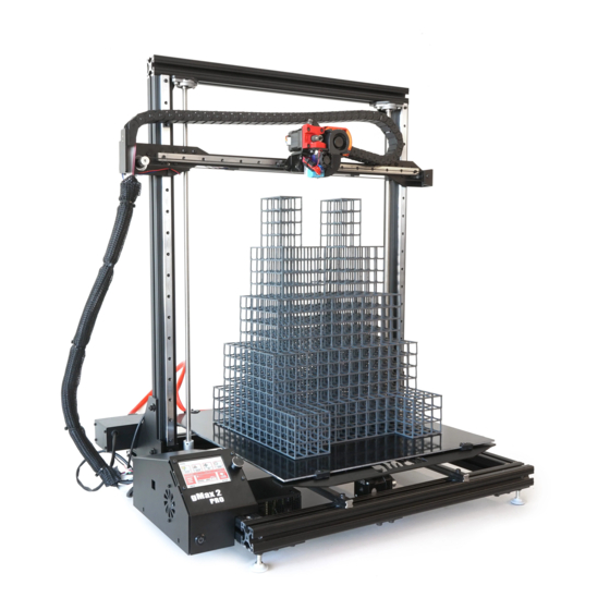
gMax 2 PRO
Unboxing and Setup
v210707
For Single and Dual Extruders
This guide should be used for the ini al unboxing and setup of your gMax2 3D printer.
Please Use the addi onal guide for the first use of your printer.
Make sure to inspect the printer through the unboxing process for loose
wires or damage. Retain the original packaging for future use.
Advertisement

Related Manuals for gCreate gMax 2 PRO


Summary of Contents for gCreate gMax 2 PRO
- Page 1 2 PRO Unboxing and Setup v210707 For Single and Dual Extruders This guide should be used for the ini al unboxing and setup of your gMax2 3D printer. Please Use the addi onal guide for the first use of your printer.
- Page 2 Install Extruder Images show a Single extruder. Pages 1-5 follow the same installa on process for both Single and Dual Extruders 1. Open the accessory box and remove the extruder and hardware. The extruder needs to be installed on the linear block using (3) M3x8mm socket head screws.
- Page 3 Plug In Extruder Flip Up 1. Loosen the two bolts on the extruder blower fan to gain access to the electronics. Loosen 2. Plug in the ribbon cable #1 into the socket closest to the motor and #2 in the other socket. 3.
- Page 4 Rotate Upper Gantry Tall Rubber Spacer Note Make sure T-Nut rubber spacers are in place. They can be easily reinstalled if they fall out. Short Rubber Spacer Use M5 hex key to loosen bolts on both sides. See next Page Pg 3...
- Page 5 Slide Down Upper Gantry Slide into Slide un l flat against coupler the lower frame 1. Slide the upper rails down un l they lay flat against the lower frame. Make sure the lead screw slides all the way into the coupler. Turn the coupler by hand to ensure a solid connec on.
- Page 6 Tighten Set Screws 1. Line up the coupler set screw with the flat spot on the lead screw and ghten both set screws on each coupler. Insert and ghten set screw Insert and ghten set screw Match set screw loca on with the flat spot on the lead screw.
- Page 7 Plug in Filament Run-Out Sensor 1. Plug in the (red, black, white) filament sensor wire from the runout sensor to the back of the printer in the spot labeled “Runout”. Note The runout sensor wire has two connectors to allow for two sensors to be plugged in.
- Page 8 Install Filament Spool Holder 1. Loosen the filament spool bracket knob and t-nut. 2. Slide the filament spool bracket on to the le side of the top rail and ghten the knob to secure it. Runout sensor 3. Install the runout sensor on the top rail with M6x16mm and tnut.
-
Page 9: Plug In And Turn On
Plug In and Turn On 1. Use the supplied power cable from the accessory box and plug in the printer. 2. Make sure to turn on the power supply and push the power bu on on the printer Plug in Printer Turn On Printer Turn On Power Supply 3.
Need help?
Do you have a question about the gMax 2 PRO and is the answer not in the manual?
Questions and answers