Table of Contents
Advertisement
Quick Links
Advertisement
Table of Contents

Related Manuals for Merits P335


Summary of Contents for Merits P335
- Page 1 ��mErits www.meritsusa.com > Power Chair P335...
-
Page 2: Table Of Contents
Owner's Manual Table of Contents Introduction Indi cati ons For Use -- -- -- -- -- -- -- -- -- -- -- -- -- -- -- - -- -- -- -- -- -- -- -- -- -- -- -- -- - Qu ant ity of C ont ent s -- Dev ice Des crip tion -- -- -- -- -- -- -- -- -- -- -- -- -- -- -- -- Safety Instructions... - Page 3 Welcome aboard your new powerbase wheelchair, and thank you for choosing our product. Please read this manual carefully, and follow all instructions before attempting to operate your powerbase wheelchair for the first time. If there is anything in this manual that you do not understand, or if you require additional assistance for setting up your powerbase wheelchair, please contact your local dealer.
-
Page 4: Indications For Use
Owner's Manual ■ Indications For Use The Merits P335 Powered Wheelchair is to provide indoor and outdoor mobility to p ersons limited to a seating position that are capable of operating a powered wheelchair. [雲震;孟悶言悶 Cauhons dewceto sale byoron theorderofa physlClan | 小... -
Page 5: Device Description
Merits Flux-P335 Powered Wheelchair is battery powered, front wheel motor driven and is controlled by the PG power wheelchair R-Net 120amp controller. The user interface is a joystick. P335 is powered by two 12 VDC 60ah (M34) batteries. The batteries are charged by a 6A off-board charger connected with 3-pin Microphone Connector to the charging socket on the joystick. - Page 6 The Seating System f o r Powered Wheelchair use the Merits Model P335 Power Wheelchair as the base unit f o r the tilting, reclining and elevating System. The Seating System and base unit is to be sold together. Model P335 Powered Wheelchai「is battery powered, center wheel motor driven and is...
- Page 7 Introduction...
-
Page 8: Practice Before Operating
Owner's Manual FaiIure tofoIIow these instructions may resuIt in damage to the powerbase wheelchair or serious injury. ■ Practice Before Operating Find an open area such as a park and have an assistant to help you practice until you have confidence operating this vehicle. Make sure that the power is off before getting in or out of the seat. - Page 9 Getting familiar with this vehicle First, practice moving forward. Be sure to set the speed to the lowest setting. � After becoming familiar with moving forward, practice making "S" turns. Once you are familiar with "S" turns, practice moving in reverse. Note that at any speed control setting, the vehicle moves more slowly in reverse than forward...
-
Page 10: Safety Considerations
Owner's Manual - Safety Considerations ■ Do not carry any passengers Do not drive across a slope Do not drink and drive Do not tow a trailer Consul t your p h ysician to determine if your med ications impair your ability to control this vehicle Do not turn on or use hand-held personal communication devices such as citizens band(CB) -
Page 11: Occupied Motor Vehicle Transport
■ Occupied Motor Vehicle Transport The power chair user should transfer into the vehicle seat a nd use the vehicle-installed restraint system if and whenever feasible. The power chair should then be stored and secured in the vehicle If it is found necessary at the user's discretion to secure a power chair to a vehicle, the vehicle must be equipped with a Wheelchair Tie-down and Occupant Restraint System that has been installed in accordance with the tie-down manufacturer's instructions. - Page 12 Owner's Manual Warnings • WARNING! No alterations or substitutions should be made to the power chair securement points or to the structural frame components without prior consent from your authorized provider • WARNING! Belt restraints must not be held away from the body by power chair components such as armrests or wheels.
- Page 13 Warnings Cautions...
-
Page 14: Emc
Owner's Manual •EMC This vehicle has an immunity level of 20 v/m which should protect it from Electromagnetic lnterference(EMI) from radio wave sources. The rapid development of electronics, especially in the area of communications, has saturated our environment with electromagnetic (radio) waves that are emitted by television, radio and communication signals. - Page 15 3) If unintended movement or brake release occurs, turn the powered wheelchair off as soon as it is safe. 4) Be aware that adding accessories or components, or modifying the powered wheelchair, may make it more susceptible to interference from radio wave sources.
-
Page 16: Driving Outdoors
Owner's Manual Driving Outdoors ■ When you are on the road, please pay attention to the following: Do not drive in traffic. Do not drive beside a river, port, or lake without a fence or railing. If possible, do not drive If possible, do not drive during the rain. - Page 17 Make sure that there are no obstacles behind you when in reverse. We recommend to set up the speed at the lowest setting for reversing. Do not make sudden stops, weave erratically, or make sharp turns. Keep your arms on or inside the armrests and feet on the footrest at all times.
-
Page 18: Driving On Various Terrains
Owner's Manual Driving on Various Terrains [ 三三三三三 三 三 三 三 三f盃\ ■ 璧 闆 \ [ ° Do not attempt to climb a hill greater than 7.5 (Refer to specification on page 17.) Do not reverse while driving up a hill. Forward only. - Page 19 , Use low speed while driving down hill. When braking while moving down hill, the wheelchair will take longer to come to a complete stop. Do not get on and off on a hill. Always stop on the level surface to get in and get out of the vehicle.
-
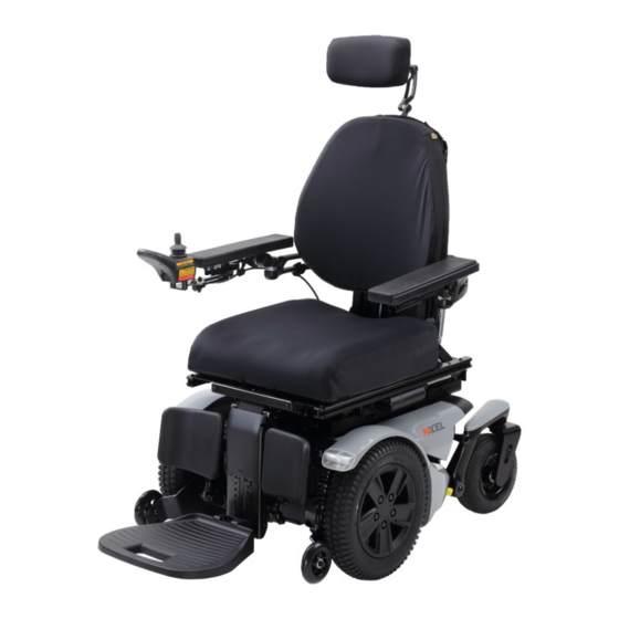
Page 20: Familiarize Yourself With Your Powerbase Wheelchair Feature Diagram
Owner's Manual Familiarize yourself with your powerbase wheelchair ■ Feature Diagram 三 :菩言三三三 三三三[三三写y P335 _ Armrest m all 『 言 薑 三 一 『 = 一 量 『 『... -
Page 21: Te Rm Ino Log Y
Powerbase Wheelchair Specifications ■ Model No P335 (Rehab seat) Length 46.5" Width 25.25" Seat Width 14"-22" 17.5"-19 .5" Seat Height (from ground) up to 6mph Speed Range up to 12.2 miles Weight Capacity 3001bs Base Weight 1471bs Seat Weight 221bs... - Page 22 Owner's Manual Freewheel Lever: For convenience, your powerbase wheelchair is equipped with freewheel levers. These levers allow you to disengage the drive motors and maneuver the chair manually. Type B applied parts: seat, armrest, foot plate, joystick module. Classification: Internal powered equipment by 24 VDC, Class II in charging mode. Mains connection of battery charger: 100-120 VAC, 50/60 Hz.
- Page 23 ■ Battery Removal: (1) Turn off the power to the controller (2) Make sure that the power chai「is in drive mode (3) Remove the rear cover by squeezing the release handles. (Fig A 1) (4) Lifting the rear cover up and away from the power base. (Fig A2) (5) Disconnect the quick release battery connectors.
-
Page 24: Armrest Adjustment
Owner's Manual ■ Armrest adjustment Fig 81 Angle ad」ustment: (1) Position (A), use the hexagonal open-end wrench to adjust the upward and downward angles of the armrest assembly. (Fig 81-1) Fig B1-1 (2) Position (B), use a hexagon wrench to ad」ust the outward and inward angles of the armrest assembly. -
Page 25: Joystick Adjustment -- - 一
■ Joystick Adjustment Adjustment of the joystick position Swing back controller bracket. (Fig C1) Fig C1 (1) Use Allen key to loosen both screws, then move controller bracket forward and backward to desired position, tretighten screws and lock armrest brace in receiver. (Fig C2) Fig C2 -... -
Page 26: Seat Width Adjustment
Owner's Manual ■ Seat width adjustment l � . " 二 Fig D1 (1) Use a hexagonal wrench to remove 9 screws. The seat width is 14"-22", and the width of the seat can be adjusted every 2". After adjusting as required, tighten the 9 screws.(Fig D1-1, Fig D1-2) -... -
Page 27: Seat Depth Adjustment
■ Seat depth adjustment (1) Use a hex wrench to remove the screws and remove the 4 seat plates.(Fig D2-1) Fig D2-1 (2) Use a hex open-end wrench to loosen the No. 1 hex screw(total 8 pcs) without removing it.(Fig D2-2) (3) Use a hexagon wrench to remove the No. -
Page 28: Power Articulating Foot Platform
To accomplish this it may be necessary to raise the Footplate to Floor Height which is adjustable in 0.6"(16mm ) increments. Failure to do so may result in damage to the wheelchair or personal injury to the user Unit P335 Footplate Clearance 60 mm(2. 4" ) 一... - Page 29 ■ Assemble Power Articulating Foot Platform to seating system The power articulating foot platform maintains the correct knee-to-heel measurements when the user's legs are elevated. (1)Install the power articulating foot platform . (a)lnstall the power articulating foot platform <81 > onto the square bar stock of seat.
- Page 30 Owner's Manual ■ Calf-pad horizontal position adjustment Parallel screws fix the lateral positioning (width) of the calf-pad. (1)Use Allen key to loosen four screws <D2>. (Fig 6) (2)Adjust the calf-pad <D1 > to desired position. (Fig 6) (3)Use Allen key to tighten four screws <D2>. (Fig 6) Fig 6 一...
- Page 31 ■ Calf-pad depth and height position adjustment Single point of adjustment allows for depth an d height of the calf-pad. (1)Calf-pad depth adjustment. (a)Use Allen key to loosen the screw <D3>. (Fig 7) (b)Adjust the calf-pad <D1> to desired position. (Fig 7) (c)Use Allen key to tighten the screw <D3>.
- Page 32 Owner's Manual ■ Calf-pad angle adjustment The calf-pad will rotate with the use's leg, this sets a stop for the lowest position - loosen and rotated as needed. (1)Use Allen key to loosen the screw <D4>. (Fig 9) (2)Adjust the calf-pad <D1 > to desired position. (Fig 9) (3)Use Allen key to tighten the screw <D4>.
- Page 33 ■ Leg length setup (1)Use Allen key to loosen four screws <E2>. (Fig 11) (2)Pull out leg length <E1> . (Fig 11) (3)Setup the Footplate <E3> to desired position. (Fig 11) (4)Use Allen key to tighten four screws <E2>. (Fig 11) -P1: Highest fixed position 1 O"...
- Page 34 Owner's Manual ■ Filp-up footplate angle adjustment (1)Filp-up the footplate <E3> for easy access. (Fig 12) (2)With an Allen key, simply turn the bolt <E6> clockwise to increase the angle or counterclockwise to decrease it. (Fig 12) (3)Hold bolt <E6> with wrench and loosen the nut <E5>. (Fig 12) (4)Choose the right angle and tighten the bolt <E6>...
- Page 35 Power Articulating Foot Platform...
-
Page 36: Manual Freewheel Lever
Owner's Manual ' . ■ Manual Freewheel Levers: The powerbase wheelchair has a manual freewheel lever on each parking brake Manual freewheel levers enable you to disengage parking brake and maneuver the chair manually. WARNING! Do not use the powerbase wheelchair while the drive motors are disengaged! Do not disengage the drive motors when the powerbase wheelchair is on an incline, as the unit could roll on its own, causing... - Page 37 2.R-NET Controller Operation 2.1 Controls/JSM-LED LED JOYSTICK MODULE Joystick Charger Socket Communication Cable CONTROL PANEL VAfllANTS Without Lighting JSM-LED 2.1.1 Buttons/Indicator BUTTONS 二口 乙工 Hom Button On/Off Button Battery Gouge Actuator Indicator Mode Button 『 雪 CO 0CX 》 『 Maximum Speed / Profile Indicator 羣...
- Page 38 Owner's Manual Battery Gauge The battery gauge shows you that the wheelchai「is switched on. It also indicates the operating status of the wheelchair. Details are given in section 3 If the battery gauge shows red, yellow and green, the batteries are charged (LEDs 1-10) If the battery gauge shows」ust red and yellow, then you should charge the batteries as soon as you can.
- Page 39 Speed I Profile Decrease Button This button decreases the maximum speed setting or, if the control system is programmed for drive profile operation, selects a lower drive profile It is possible to program the control system so this button has no effect while the wheelchai「is being driven Speed I Profile Increase Button This button increases the maximum speed setting or, if the control system is...
- Page 40 Owner's Manual 2.1.2 Control System Status indication The battery gauge and maximum speed /profile indicator show the status of the control system. A number of supposedly defective control systems returned to us are subsequently found to operate correctly. This indicates that many reported faults are due to wheelchair problems rather than the control system Battery Gauge is Steady This indicates that all is well...
- Page 41 Below is a list of self-help actions. Try to use this list before you contact your service agent. Go to the number in the list which matches the number of flashing LEDs and follow the instructions If the problem persists after you have made the checks described below contact your service agent 1 LED The battery needs charging or there is a bad connection to the battery Check the connections to...
- Page 42 Owner's Manual Speed Indication The number of LEDs illuminated shows the maximum speed setting. For example, if the setting is speed level 4, then the four left hand LEDs will be illuminated Profile Indication The LED illuminated shows the selected drive profile. For example, if drive profile 4 is selected, then the fourth LEDs from the left will be illuminated Maximum Speed I Profile Indicator Ripples Up and Down This indicates the control system is locked...
- Page 43 R-NET Controller Operation...
- Page 44 Owner's Manual 2.3 Module Wiring 2.3. l Power Module Wiring The following diagram gives details of the LED Power Module connections 戶 翌 MOTOR Lett• : 「二二 三 ]: 「 二 otk: 壼 * Assumes no Motor Swa p progra m ming has been u n derta k en Jo y sl d AcUol...
- Page 45 2.3.2 ISM Wiring The following diagram gives details o the ISM connections k;luolor Chomels 鬪缸 Lett L lnh 4 ig h ts Model: ISM-X-L X=4, Actuator channels 1-4 Axis 雲 峒 户 6, Actuator channels 1-6 Axis L=Lights Function Right Lights lnh 5 '...
- Page 46 Owner's Manual 2.4 ISM Actuators Channels Channel 1 : Tilt Channel 2 : Recline Channel 3 : L-ELR Channel 4 : R-ELR Channel 5 : Seat Elevator Channel 6 : Footplate JSM-LED Actuators Display _ 『 · Til t Recline L-ELR...
- Page 47 · · · ·· · 巴璽l - 「 l ,0U. uo'" '" `noc umw ,MOJ '"n ' " 己"' LR MC ·"·u `'T, S P0" 0EO' -' R-ELR Footglate Recline+ Footplate 『 雪 『 Seat Elevator...
- Page 48 Owner's Manual 3. Charger Connector An Off-Board Charger can be connected to the Joystick Module's charger connector The charger connector is Neutrik 3 pin type NC3FPP or equivalent, and the maximum charging current is 12A rms. Only chargers fitted with Neutrik NC3MX plugs should be connected into the Joystick Module.
-
Page 49: Batteries And Charging
■ Batteries and Charging Your Power Wheelchair uses two long-lasting, 12-volt batteries. These batteries are sealed, maintenance free, deep-cycle batteries. Since they are sealed, there is no need to check the electrolyte (fluid) level. Deep-cycle batteries are designed to handle a deep discharge. Though they are similar in appearance to automotive batteries, they are not interchangeable. - Page 50 Owner's Manual Note: If you are storing a power wheelchair for an extended period of time, you may wish to block the unit up off the ground with several boards under the frame. This keeps the tires off the ground to prevent the possibility of flat spots developing. If you intend to use public transportation while using your power wheelchair, you must contact in advance the transportation provider to determine their specific requirements.
-
Page 51: Care And Maintenance
CARE AND MAINTENANCE Your powerbase wheelchair requires a minimal amount of care and maintenance. If you do not feel confident in your ability to perform the maintenance listed below, you may schedule inspection and maintenance at your authorized. The following areas require periodic inspection and/or care and maintenance. - Page 52 Owner's Manual Cleaning and disinfection • Use a damp cloth and mild, non-abrasive cleanser to clean the plastic and metal parts of your powerbase wheelchair. Avoid using products that may scratch the surface of your powerbase wheelchair. • If necessary, clean your product with an approved disinfectant. Make sure the disinfectant is safe for use on your product before application.
- Page 53 DAILY CHECKS • With the controller turned off, check the joystick. Make sure it is not bent or damaged and that it returns to center when you release it. Check the rubber boot around the base of the joystick for damage. Visually inspect the boot only. Do not handle or try to repai「it. See your authorized service center if there is a problem.
- Page 54 Owner's Manual MONTHLY CHECKS • Check that the anti-tip wheels do not rub the ground when you are operating the powerbase wheelchair; adjust them as necessary. • Check for extreme wear on the anti-tip wheels. Replace them as necessary. • Check for drive tire wear. See an authorized provider for repair. •...
- Page 55 Wheel replacement If your powerbase wheelchair is equipped with pneumatic tires and you have a flat tire , you can have the tube replaced. If your powerbase wheelchair is equipped with a solid tire insert, either the solid insert or the entire wheel must be replaced depending on the model.
- Page 56 Owner's Manual Wiring harnesses • Regularly check all wiring connections. • Regularly check all wiring insulation, including the charger power cord, for wear or damage. • Have your authorized dealer repair or replace any damaged connector, connection, or insulation that you find before using your powerbase wheelchair again. •...
- Page 57 Console, charger, and electronic controller module • Keep these areas away from moisture. • Before operating your powerbase wheelchair, allow any of these areas to dry thoroughly if they have been exposed to moisture. Fuses To replace a fuse: 1. Remove the fuse by pulling it straight out of its slot. 2.
- Page 58 Owner's Manual Storing your powerbase wheelchair If you plan on not using your powerbase wheelchair for an extended period of time, it is best to: 1. Fully charge its batteries prior to storage. 2. Disconnect the batteries from the powerbase wheelchair. 3.
- Page 59 - 』 \_·一- 「 - -一-—-— — — — — -— —-一 — -—-—-—-—-j\__-—-—-—-—-—- 亂渾 [ 『 晝 = 王 臺...
-
Page 60: Iec Symbols
Owner's Manual - - - IEC Symbols Direct current Protect against splashing water IPX4 心、 Attention, consult accompanying document. ON/ OFF Button on the controller 6A/24V Use DC 24V/6A charger . Follow the instructions for use 介 T ype B appli ed part 回... -
Page 61: Warranty
► ◄ W a rr a n ty |Limited Warranty| Corporation warrants to the original purchaser of this wheelchair product that it is free of defect in material and workmanship and that, when operated within the guidelines and restrictions of this manual, will remain so free of defect in material and workmanship for a period of 18 months from the original date of purchase. -
Page 62: Warranty Registration
Owner's Manual ► ◄ Warranty Registration WARRANTY REGISTRATION MODEL NO. SERIAL NO. DATE PURCHASED NAME ADDRESS CITY STATE DEALER NAME STAMP RETURN ADDRESS · 『 『... -
Page 63: Troubleshooting Tips
TROUBlESHOOTING TIPS If your power chair or scooter is not operating properly, please take the following steps prior to calling Technical Support. Load-test Batteries-See Figure 1 1. Attach Battery Load-tester to battery. Observe polarity: Red is Positive-Black is Negative 2. Hold load switch on for 10 seconds. - Page 64 Disclosure Information (150 7176-15:1996) Min. Max. Max. ° ° Overall length with legrest 1210mm/47.6" Seat plane angle -- Overall width 627mm/24. 7 " Effective depth 356mm/14" 508mm/20" -- Folded length Effective seat 356mm/14" 560mm/22" -- -- width Folded height Seat surface 445mm/17.5"...
- Page 68 www.meritsusa.com 4245 EVANS AVENUE. FORT MYERS. FL 33901 TEL: 1-800-963-7487, 1-239-772-0579 FAX: 1-239-574-2661 Rev. 0. 2021/10/04...
Need help?
Do you have a question about the P335 and is the answer not in the manual?
Questions and answers