Table of Contents
Advertisement
Quick Links
Advertisement
Table of Contents

Related Manuals for Merits P321 Series


Summary of Contents for Merits P321 Series
- Page 1 Merits P321 series Service Manual Nov.10.2006 V1...
-
Page 2: Table Of Contents
Index 1. Introduction ................1 2. Service guide ................1 2.1. How to replace or repair the seat assembly ..........1 2.1.1. To replace the seat body ................... 1 2.1.2. To replace the seat base plate assembly ............2 2.1.3. To replace the seat post..................2 2.1.4. -
Page 3: Introduction
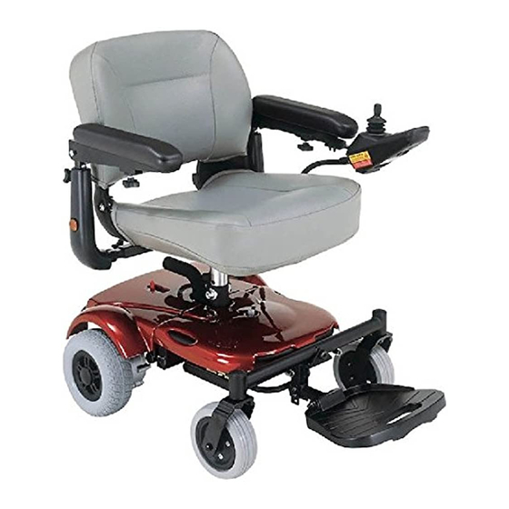
1. Introduction The purpose of this manual is to provide dealers and/or distributors with the product information and instructions that are required for servicing the P321 powerchair. 2. Service guide The P321 powerchair consists of three main parts: n Seat assembly n Body assembly n Electrical system (Please refer to P3 series Shark or VR2 service manual) -
Page 4: To Replace The Seat Base Plate Assembly
2.1.2. To replace the seat base plate assembly ◆ When should you replace the seat base plate assembly? ◇ If the seat base plate is deformation. ◇ If the seat base plate out of shape due to an accident. ◆ How to replace the seat base plate assembly? ◇... -
Page 5: To Replace The Left/Right Armrest
2.1.4. To replace the left/right armrest ◆ When should you replace the armrest? ◇ If the armrest is worn out. ◇ If the armrest is pierced or scratched by something. ◇ If the powerchair crashed cause the armrest out of shape. ◆... -
Page 6: How To Replace Or Repair The Body Assembly
Note: The arm tube protective shrouds (4.43 and 4.45) are option parts for powerchair. 2.2. How to replace or repair the body assembly The Body Assembly includes shroud, footplate, anti- tipper wheel, caster wheel assembly, driver wheel assembly, front frame assembly and rear frame assembly. -
Page 7: To Replace The Anti-Tipper Wheel
the screw (8.08) and loosen the nut (8.10) and then replace the footplate assembly. Hole the screw (8.02) and loosen the nut (8.04) then remove the footplate. If the footplate is worn out, then replace it. 2.2.3. To replace the anti-tipper wheel ◆... -
Page 8: To Replace The Caster Wheel Assembly
2.2.4. To replace the caster wheel assembly ◆ When should you replace the caster wheel assembly? ◇ If the caster wheel assembly is worn out. ◇ If the stud (5.05) of caster wheel assembly is broken. ◇ If the caster wheel assembly is out of shape due to an accident. ◆... -
Page 9: To Replace The Driver Wheel Assembly
deformed. a. Hold the screw (5.06) and loosen the nut (5.09) and then remove the caster wheel. b. If the PU tire is worn out, then replace it. 2.2.5. To replace the driver wheel assembly ◆ When should you replace the driver wheel assembly? ◇... -
Page 10: To Replace The Frame
Replace the driver wheel by the following steps if it is worn out or deformed. Remove the cap(5.62) and follow preceding step above. 2.2.6. To replace the frame ◆ When should you replace the frame? ◇ If the frame is deformation. ◇... - Page 11 noise or sticking motion during operation of the powerchair. a. Remove the seat assembly, the shroud, the footplate and the caster wheel assembly by step 2.1, 2.2.1, 2.2.2, 2.2.4 previously. b. Use hex tools to loosen six pieces the screw (5.60) to remove motor and gearbox assembly.
- Page 12 articulating beam assembly. g. Remove the main tube cap (1.03 and 1.04). h. Check for deformations or cracks on the front frame and replace the front frame should they exist. i. Remove the shroud, the anti-tipper wheel and the driver wheel assembly by step 2.2.1, 2.2.3, 2.2.5 previously.
- Page 13 q. Remove the cap (1.36, 1.37 and 1.43). r. Remove the foam sleeve (1.42). s. Check for deformations or cracks on the rear frame and replace the rear frame should they exist.
Need help?
Do you have a question about the P321 Series and is the answer not in the manual?
Questions and answers