Table of Contents
Advertisement
Advertisement
Table of Contents

Related Manuals for Merits P322


Summary of Contents for Merits P322
- Page 1 Power Chair P322...
-
Page 2: Table Of Contents
Indications For Use Quantity of Contents Device Description Seat Removal Shroud Removal Attach Shroud Remove Battery Operating Your Powerbase Wheelcaair Seat Height Adjustment Armrest Width/Height Adjustment Armrest Angle Adjustment Footrest Angle Adjustment Headrest Height Adjustment Joystick Postion Adjustment Manual Freewheel Levers VR2 Controller Operation Batteries and Charging Care And Maintenance... - Page 3 adjusted...
-
Page 4: Indications For Use
Indications For Use The Merits Model P322 Powered Wheelchair is to provide mobility to persons limited to a seated position that are capable of operating a powered wheelchair. Cautions Federal law restricts this device to sale by or on the order of a physician. -
Page 5: Device Description
Model P322 Powered Wheelchair is battery powered, front wheel motor driven and is controlled by the PG power wheelchair VR-2 50amp controller. The user interface is a joystick. P322 is powered by two 12 VDC 34ah (U1) batteries. The batteries are charged by a 4A off-board charger connected with 3-pin Microphone Connector to the charging socket on the joystick. - Page 6 Battery Gauge On / Off Horn Speed Meter Decrease Speed Increase Speed Joystick...
- Page 7 SAFETY WARNING YOUR AUTHORIZED DEALER, PROVIDER, THERAPIST(S), AND/OR OTHER HEALTHCARE PROFESSIONALS ARE RESPONSIBLE FOR DETERMINING YOUR REQUIREMENT FOR A SEAT BELT FOR SAFE OPERATION OF YOUR MOBILITY DEVICE. REQUIRING A SEAT BELT TO SAFELY OPERATE YOUR MOBILITY PRODUCT, MAKE SURE IT IS FASTENED SECURELY IN ORDER TO REDUCE THE POSSIBILITY OF A FALL FROM THE MOBILITY PRODUCT.
- Page 9 Warnings DO NOT use an escalator to move a wheelchair between floors. Serious bodily injury may occur. DO NOT lean over the top of the back upholstery to reach objects from behind as this may cause the wheelchair to tip over. DO NOT shift your weight or sitting position toward the direction you are reaching as the wheelchair may tip over backwards or sideways.
- Page 11 to do so. Warning: The wheelchair might disturb the operation of devices in its environment that emit electromagnetic fields (e.g. alarm systems of shops, automatic doors)
- Page 15 Electrically Powered Wheelchair P322 maximum user weight 136Kg Year of production: Protect against splashing water:IPX4 MERITS HEALTH PRODUCTS CO., LTD. No. 18, Jingke Road, T.P.M. T Park, Nantun District, Taichung City 40852, Taiwan, R.O.C. Made In Taiwan...
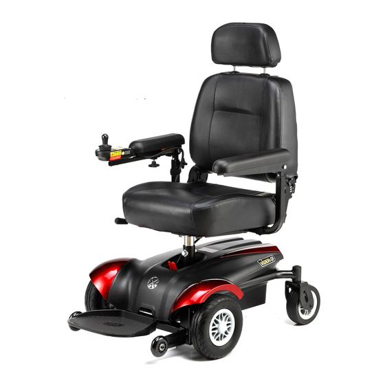
- Page 16 Joystick Armrest Seat Manual Freewheel Lever Shroud Rear Caster Footrest Drive Wheel Anti-Tipper...
- Page 17 P322 規格表 Mode No. P322 Length 84.7cm/33.4” Width 60.6cm/23.9” Seat Width 18” Seat Height 51cm~56.1cm/ (from ground) 20.1”~22.1” Seat Height 42cm~47.1cm/ (from deck) 16.5”~18.5” Speed 6.4kph/4mph Range up to 28km/18mi Weight Capacity 136kg/300lbs BaseWeight 28.5kg/62.7lb Seat Weight 17.4kg/34.8lb Battery Weight/ea...
- Page 18 Type B applied parts: seat, armrest, foot plate, joystick module. Classification: Internal powered equipment by 24 VDC, Class II in charging mode. Mains connection of battery charger: 100-120 VAC, 50/60 Hz. Braking information: 1) Running brake: Your electrical wheelchair is equipped with electromagnetic and regenerative brakes.
-
Page 20: Shroud Removal
Shroud Removal 1. Use two hands to hold the rear end of the shroud. Slightly pull up the rear end of the shroud. This will release the rear hooks from the bracket at the battery tray.(Fig D1) Fig D1 2. Holding it the same pull the shroud up, this will release the the front hooks from the bracket at the front frame. -
Page 21: Attach Shroud
Attach Shroud 1. Please note there are two hooks at the front end of shroud for matching with the front frame. (one for each LH and (Fig D4) Fig D4 2. Please note there are two hooks at the rear end of shroud for matching with the battery tray. - Page 22 5. Make sure the shroud front end touches the front frame and then slightly move the shroud from rear to front. This will make the front hooks attach to the bracket at the frame. (Fig D8) Fig D8 6. Push the rear end of the shroud. This will make the rear shroud hooks attach to the bracket at the battery tray.
-
Page 23: Remove Battery
Remove Take apart (Fig E1) (Fig E2) Take off .(Fig E3) (Fig E3) (Fig E1) (Fig E2) (Fig F) (Fig F) -
Page 26: Manual Freewheel Levers
To engage or disengage the drive motors: 1. Locate the lever on the top of the power base. 2. Push both lever forward away from the seat post to engage the drive motors (drive mode). (Fig L1) 3. Pull both lever rearward toward the seat post to disengage the drive motors (freewheel mode). -
Page 32: Batteries And Charging
Warning: Use only the battery charger supplied with the chair or an approved substitute of equal voltage and current output... - Page 33 Plug the charger outpet plug into the charging socket in the front of the controller,then plug the charger input plug into an electrical outlet.
-
Page 34: Care And Maintenance
CARE AND MAINTENANCE Your powerbase wheelchair requires a minimal amount of care and maintenance. If you do not feel confident in your ability to perform the maintenance listed below, you may schedule inspection and maintenance at your authorized dealer. The following areas require periodic inspection and/or care and maintenance. - Page 35 Cleaning and disinfection ● Use a damp cloth and mild, non-abrasive cleanser to clean the plastic and metal parts of your powerbase wheelchair. Avoid using products that may scratch the surface of your powerbase wheelchair. ● If necessary, clean your product with an approved disinfectant. Make sure the disinfectant is safe for use on your product before application.
- Page 36 DAILY CHECKS ● With the controller turned off, check the joystick. Make sure it is not bent or damaged and that it returns to center when you release it. Check the rubber boot around the base of the joystick for damage. Visually inspect the boot only. Do not handle or try to repair it. See your authorized service center if there is a problem.
-
Page 37: Monthly Checks、Yearly Checks
MONTHLY CHECKS ● Check that the anti-tip wheels do not rub the ground when you are operating the powerbase wheelchair; adjust them as necessary. ● Check for extreme wear on the anti-tip wheels. Replace them as necessary. ● Check for drive tire wear. See an authorized provider for repair. ●... -
Page 38: Wheel Replacement
Wheel replacement If your powerbase wheelchair is equipped with pneumatic tires and you have a flat tire, you can have the tube replaced. If your powerbase wheelchair is equipped with a solid tire insert, either the solid insert or the entire wheel must be replaced depending on the model. Contact your dealer for information regarding replacement wheels for your powerbase wheelchair. -
Page 39: Wiring Harnesses
Wiring harnesses ● Regularly check all wiring connections. ● Regularly check all wiring insulation, including the charger power cord, for wear or damage. ● Have your authorized dealer repair or replace any damaged connector, connection, or insulation that you find before using your powerbase wheelchair again. ●... - Page 40 Console, charger, and electronic controller module ● Keep these areas away from moisture. ● Before operating your powerbase wheelchair, allow any of these areas to dry thoroughly if they have been exposed to moisture. Fuses To replace a fuse: 1. Remove the fuse by pulling it straight out of its slot. 2.
-
Page 41: Part Lists
Controller, P&G nVR2, PM 50(D51425) Motor & Gearbox Ass’y., M9M01HA-12, LH Shroud Ass'y Motor & Gearbox Ass’y., M9M01HA-12, RH Shroud, P322 Motor Ass’y., M9HA-12, LH Battery Pack, P322 Motor Ass’y., M9HA-12, RH Footplate Ass'y. Gearbox Ass’y., M9M01 Footrest Plate Caster Wheel with Fork Ass'y. -
Page 43: Iec Symbols
IEC Symbols Direct current Protect against splashing water IPX4 Attention, consult accompanying document. ON/ OFF Button on the controller 5A/24V Use DC24V/5A charger Follow the instructions for use Type B applied part Class II Equipment... - Page 44 of the corporation.
- Page 46 elevate the drive wheels. If any of the above tests fail, contact your local dealer.
- Page 49 Rev. 0. 26/09/2012...
Need help?
Do you have a question about the P322 and is the answer not in the manual?
Questions and answers