
Subscribe to Our Youtube Channel
Related Manuals for Woodward MSLC-2


Summary of Contents for Woodward MSLC-2
- Page 1 37444F MSLC-2 Master Synchronizer and Load Control Manual Software Version 1.15xx Manual 37444F...
- Page 2 Provides other helpful information that does not fall under the warning or caution categories. Woodward reserves the right to update any portion of this publication at any time. Information provided by Woodward is believed to be correct and reliable. However, Woodward assumes no responsibility unless otherwise expressly under- taken.
- Page 3 A and 7861 controls network B. These items are found in Menu 5.1 – Interfaces In a Ring Structured application, the MSLC-2 Tie breaker control that connects segment 8 to segment 1, must have item 4544, “Basic segment number”, set for 8. The System A PT will connect on the segment 8 side of the breaker while the System B PT will connect to the segment 1 side.
- Page 4 (see ToolKit homepage, page 61 and Menu 8, page 107). Overview screens for DSLC-2 and MSLC-2 modified for redundant Ethernet with addi- tional LED and text for each Unit ID (page 115ff). For description see page 176ff.
- Page 5 Manual 37444F MSLC-2 - Master Synchronizer and Load Control Rev. Date Editor Changes or higher and device revision A or higher. Synchronizer description: Manual synchronizing. Refer to “Table 4-13: Ramping overview Synchronizing ” on page 155 for details.
-
Page 6: Table Of Contents
Install ToolKit Configuration Files ....................51 Starting ToolKit Software ......................52 Configure ToolKit Software ......................53 Connecting ToolKit and the MSLC-2 Unit ................... 54 View MSLC-2 Data with ToolKit ....................58 Configuring the MSLC-2 with ToolKit ..................59 The MSLC-2 Version Page ......................60 Menu (Setpoint) Description ........................ - Page 7 Manual 37444F MSLC-2 - Master Synchronizer and Load Control Menu 9 – Discrete Inputs / Discrete (Relay) Outputs ..............110 Menu 0 – Diagnostics ........................ 112 Overview Pages ......................... 115 Prestart Setup Procedure ........................118 Configuration Menu ........................118 Prestart Segmenting Setup ......................119 Prestart Synchronizer Setup ......................
- Page 8 Manual 37444F MSLC-2 - Master Synchronizer and Load Control Import / Export Mode ........................... 160 Process Control Mode ......................... 160 Remote Control ............................ 160 Automatic Power Transfer Control Functions ..................160 Ramping Between Modes ......................160 Utility Unload ..........................160 Local Unload ..........................
- Page 9 Figure 3-6: ToolKit - home page (MSLC-2 configured as tie-breaker control) ............62 Figure 3-10: ToolKit - home page - MSLC-2 configured as utility breaker control ........... 64 Figure 3-11: ToolKit - home page - MSLC-2 configured as tie-breaker control ............65 Figure 3-12: ToolKit - home page - segments ......................
- Page 10 Figure 8-8: Not supported application ........................172 Figure 8-9: Visualization and remote control by PLC via RS-485 interface ............173 Figure 9-1: MSLC-2 - interface overview (housing - side view) ................175 Figure 9-2: Modbus - visualization configurations....................181 Figure 9-3: Modbus - sending binary digital orders over interface ................ 185 Figure 9-4: Modbus –...
- Page 11 Manual 37444F MSLC-2 - Master Synchronizer and Load Control Table 2-1: Conversion chart - wire size ........................27 Table 2-2: Power supply - terminal assignment ...................... 28 Table 2-3: Voltage measuring – terminal assignment – System A voltage ............. 29 Table 2-4: Voltage measuring - terminal assignment –...
- Page 12 Table 3-94: Parameter – diagnostics ........................114 Table 3-95: System Status quick info at overview pages ..................115 Table 3-30: Parameter – MSLC-2 overview page ....................116 Table 3-29: Parameter – DSLC-2 overview page ....................117 Table 4-1: Low voltage system 480 V / 277 V – 3-phase with neutral ..............138 Table 4-2: Low voltage system 480 V / 277 V –...
-
Page 13: Chapter 1. General Information
Manual 37444F MSLC-2 - Master Synchronizer and Load Control Chapter 1. General Information Document Overview ≡≡≡≡≡≡≡≡≡≡≡≡≡≡≡≡≡≡≡≡≡≡≡≡≡ This manual describes the Woodward MSLC-2 Master Synchronizer and Load Control. Type English German MSLC-2 DSLC-2 – User Manual 37443 MSLC-2 – User Manual this manual ... -
Page 14: Application
≡≡≡≡≡≡≡≡≡≡≡≡≡≡≡≡≡≡≡≡≡≡≡≡≡ The Woodward MSLC-2™ control is the direct successor of the former MSLC™ master synchronizer and load control. The MSLC-2™ is a microprocessor-based overall plant load control designed for use in a system with Woodward DSLC-2 (“Digital Synchronizer and Load Control”) controls on each gen- erator to provide utility synchronizing, paralleling, loading and unloading of a three-phase generating system. -
Page 15: Load Control
MSLC-2 issues a breaker open command to separate the utility from the local bus. The ramp pause switch can be used to stop the utility unload at any point. The maximum load that the MSLC-2 can tell the individual generators to carry is their rated loads. So, in the event that the plant load is greater than the capacity of the operating generators, the utility unload will stop when 100% rated load is reached on each of the operating generators. -
Page 16: Figure 1-2: Mslc-2 Load Control Overview
Manual 37444F MSLC-2 - Master Synchronizer and Load Control Figure 1-2: MSLC-2 Load Control Overview Page 16/226 © Woodward... -
Page 17: Process Control
100% or 0%, the control will maintain that load reference until process control is established. The MSLC-2 is not capable of overloading or reverse powering the generators in an attempt to meet the process reference. The high and low limit switches mentioned above can be used to indicate that either too many or too few generators are online to maintain the process within its limits. -
Page 18: Dslc-2 / Mslc-2 Systems
DSLC-2 / MSLC-2 Systems ≡≡≡≡≡≡≡≡≡≡≡≡≡≡≡≡≡≡≡≡≡≡≡≡≡ The network addressing of the DSLC-2 / MSLC-2 allows up to 32 DSLC-2s and 16 MSLC-2s in an ap- plication. A DSLC-2 and MSLC-2 application can handle 8 segments. Discrete inputs inform the DSLC- 2s and MSLC-2s which segments each generator and utilities are operating on. If a MSLC-2 receives a discrete input to activate segment 1 and 2, it will share this information with all controls over the Ether- net bus. -
Page 19: Control Relationships In A Mslc-Dslc System
Manual 37444F MSLC-2 - Master Synchronizer and Load Control Figure 1-4: Multiple generators in isolated and utility parallel operation with utility- and tie-breaker Control Relationships in a MSLC-DSLC System A MSLC / DSLC system is defined through minimum of one MSLC device and one DSLC device. -
Page 20: Chapter 2. Installation
CAUTION To prevent damage to electronic components caused by improper handling, read and observe the pre- cautions in Woodward manual 82715, Guide for Handling and Protection of Electronic Controls, Printed Circuit Boards and Modules. NOTE The unit is capable to withstand an electrostatic powder coating process with a voltage of up to 85 kV and a current of up to 40 µA. -
Page 21: Unpacking
Protect the unit from direct exposure to water or to a condensation-prone environment. • The continuous operating range of the MSLC-2 control is –40 to +70 °C (–40 to +158 °F). • Provide adequate ventilation for cooling. Shield the unit from radiant heat sources. -
Page 22: Housing
Manual 37444F MSLC-2 - Master Synchronizer and Load Control Housing ≡≡≡≡≡≡≡≡≡≡≡≡≡≡≡≡≡≡≡≡≡≡≡≡≡ Dimensions Protective Earth Figure 2-1: Housing MSLC-2 - dimensions Page 22/226 © Woodward... -
Page 23: Installation
Manual 37444F MSLC-2 - Master Synchronizer and Load Control Installation The unit is to be mounted to the switch cabinet back using four screws with a maximum diameter of 6 mm. Drill the holes according to the dimensions in Figure 2-2 (dimensions shown in mm). -
Page 24: Terminal Arrangement
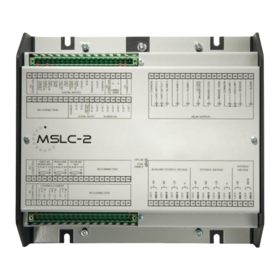
MSLC-2 - Master Synchronizer and Load Control Terminal Arrangement NOTE The Protective Earth terminal 61 is not connected on the MSLC-2. The protective earth connection at the sheet metal housing must be used instead (refer to Figure 1-2). Figure 2-3: MSLC-2 - terminal arrangement LEDs LED “Sync Enable”... -
Page 25: Wiring Diagrams
Manual 37444F MSLC-2 - Master Synchronizer and Load Control Wiring Diagrams ≡≡≡≡≡≡≡≡≡≡≡≡≡≡≡≡≡≡≡≡≡≡≡≡≡ Figure 2-4: Wiring diagram - MSLC-2 - 1/2 © Woodward Page 25/226... -
Page 26: Figure 2-5: Wiring Diagram - Mslc-2 - 2/2
Manual 37444F MSLC-2 - Master Synchronizer and Load Control Figure 2-5: Wiring diagram - MSLC-2 - 2/2 Page 26/226 © Woodward... -
Page 27: Connections
Manual 37444F MSLC-2 - Master Synchronizer and Load Control Connections ≡≡≡≡≡≡≡≡≡≡≡≡≡≡≡≡≡≡≡≡≡≡≡≡≡ WARNING All technical data and ratings indicated in this chapter are not definite! Only the values indicated in par- agraph Appendix A. Technical Data on page 196 are valid! The following chart may be used to convert square millimeters [mm²] to AWG and vice versa:... -
Page 28: Power Supply
Table 2-2: Power supply - terminal assignment Figure 2-7: Power supply - crank waveform at maximum load NOTE Woodward recommends to use one of the following slow-acting protective devices in the supply line to terminal 63: Fuse NEOZED D01 6A or equivalent ... -
Page 29: Voltage Measuring
DO NOT use both sets of voltage measuring inputs. The control unit will not measure voltage correctly if the 120 V and 480 V inputs are utilized simultaneously. NOTE Woodward recommends protecting the voltage measuring inputs with slow-acting fuses rated for 2 to 6 A. Voltage Measuring: System A Figure 2-8: Voltage measuring –... -
Page 30: Figure 2-9: Voltage Measuring - System A Windings, 3Ph 4W Od
Manual 37444F MSLC-2 - Master Synchronizer and Load Control Voltage Measuring: System A Parameter Setting '3Ph 4W OD' (3-phase, 4-wire, Open delta) A generator system that is connected to the load through a 3-phase, 4-wire connection but have the device wired for a 3-phase, 3-wire installation may have the L2 phase grounded on the secondary side. -
Page 31: Figure 2-11: Voltage Measuring - System A Windings, 3Ph 4W
Manual 37444F MSLC-2 - Master Synchronizer and Load Control Voltage Measuring: System A, Parameter Setting '3Ph 4W' (3-phase, 4-wire) Figure 2-11: Voltage measuring – system A windings, 3Ph 4W Figure 2-12: Voltage measuring – system A measuring inputs, 3Ph 4W... -
Page 32: Figure 2-13: Voltage Measuring - System A Windings, 3Ph 3W
Manual 37444F MSLC-2 - Master Synchronizer and Load Control Voltage Measuring: System A, Parameter Setting '3Ph 3W' (3-phase, 3-wire) Figure 2-13: Voltage measuring – system A windings, 3Ph 3W Figure 2-14: Voltage measuring – system A measuring inputs, 3Ph 3W... -
Page 33: Figure 2-15: Voltage Measuring - System B
Manual 37444F MSLC-2 - Master Synchronizer and Load Control Voltage Measuring: System B Figure 2-15: Voltage measuring – system B Figure Terminal Description 120 Vac 2.5 mm² System B Voltage AØ (L1) 480 Vac 2.5 mm² 120 Vac 2.5 mm²... -
Page 34: Figure 2-16: Voltage Measuring - System B Measuring Inputs, 1Ph 2W (Phase-Neutral)
2W' (1-phase, 2-wire) NOTE The 1-phase, 2-wire measurement may be performed phase-neutral or phase-phase. Please note to configure and wire the MSLC-2 consistently. Refer to the chapter Configuration & Operation. '1Ph 2W' Phase-Neutral Measuring Figure 2-16: Voltage measuring – system B measuring inputs, 1Ph 2W (phase-neutral) -
Page 35: Figure 2-18: Voltage Measuring - Auxiliary System B
480 V, the 480 V input terminals must be used for proper measurement. NOTE If the MSLC-2 is intended to be operated in parallel with the mains, the mains voltage measuring inputs must be connected. If an external mains decoupling is performed, jumpers between system B and aux- iliary system B voltage measuring inputs may be installed. -
Page 36: Figure 2-19: Voltage Measuring - Auxiliary System B Pt Windings, 3Ph 4W
Manual 37444F MSLC-2 - Master Synchronizer and Load Control Voltage Measuring: Auxiliary System B, Parameter Setting '3Ph 4W' (3-phase, 4-wire) Figure 2-19: Voltage measuring - auxiliary system B PT windings, 3Ph 4W Figure 2-20: Voltage measuring - auxiliary system B measuring inputs, 3Ph 4W... -
Page 37: Figure 2-21: Voltage Measuring - Auxiliary System B Pt Windings, 3Ph 3W
Manual 37444F MSLC-2 - Master Synchronizer and Load Control Voltage Measuring: Auxiliary System B, Parameter Setting '3Ph 3W' (3-phase, 3-wire) Figure 2-21: Voltage measuring - auxiliary system B PT windings, 3Ph 3W Figure 2-22: Voltage measuring - auxiliary system B measuring inputs, 3Ph 3W... -
Page 38: Current Measuring
Manual 37444F MSLC-2 - Master Synchronizer and Load Control Current Measuring CAUTION Before disconnecting the device, ensure that the current transformer/CT is short-circuited. System A Current NOTE Generally, one line of the current transformers secondary is to be grounded close to the CT. -
Page 39: Figure 2-24: Current Measuring - System A, L1 L2 L3
Manual 37444F MSLC-2 - Master Synchronizer and Load Control Current Measuring: System A, Parameter Setting 'L1 L2 Figure 2-24: Current measuring – system A, L1 L2 L3 L1 L2 L3 Wiring terminals Notes MSLC-2 terminal Phase X2 - A(L1) X1 - A(L1) -
Page 40: Figure 2-26: Power Measuring - Direction Of Power
Manual 37444F MSLC-2 - Master Synchronizer and Load Control Power Measuring If the unit's current transformers are wired according to the diagram shown, the following values are displayed. Utility Breaker MSLC-2 Parameter Description Sign displayed Mains real power Importing KW (from Utility) -
Page 41: Power Factor Definition
Manual 37444F MSLC-2 - Master Synchronizer and Load Control Power Factor Definition The phasor diagram is used from the generator's view. Power factor is defined as follows. Power Factor is defined as a ratio of the real power to apparent power. In a purely resistive circuit, the voltage and current waveforms are instep resulting in a ratio or power factor of 1.00 (often referred to... -
Page 42: Figure 2-27: Phasor Diagram - Inductive / Capacitive
Manual 37444F MSLC-2 - Master Synchronizer and Load Control Phasor diagram: inductive capacitive Figure 2-27: Phasor diagram – inductive / capacitive Page 42/226 © Woodward... -
Page 43: Discrete Inputs
Manual 37444F MSLC-2 - Master Synchronizer and Load Control Discrete Inputs Discrete Inputs: Signal Polarity The discrete inputs are electrically isolated which permits the polarity of the connections to be either positive or negative. NOTE All discrete inputs must use the same polarity, either positive or negative signals, due to the common ground. -
Page 44: Table 2-19: Discrete Input - Terminal Assignment 2/2
Remote reference is activated by closing both setpoint raise and setpoint lower switches at the same time. The MSLC-2 can only load the associated generators to 100%. If this is not enough capacity to un- load the utility, the unload ramps stops at 100% rated load on the associated generators. The genera- tor high limit alarm, if enabled, will activate at this time. -
Page 45: Relay Outputs
Manual 37444F MSLC-2 - Master Synchronizer and Load Control Relay Outputs Figure 2-30: Relay outputs Terminal Description Term. Com. Type Form A, N.O. make contact Relay output [R 01] {all} Alarm (Self-Test OK) N.O. 2.5 mm² Relay output [R 02]... -
Page 46: Table 2-22: Relay Outputs Driven By
Manual 37444F MSLC-2 - Master Synchronizer and Load Control Alarm Reserve High Breaker Breaker LCL/ Alarm 1 Alarm 2 Alarm 3 Load Load Limit Limit Open Close switch 1 switch 2 Breaker Open Self-Test Reserve High load limit High process limit... -
Page 47: Analog Inputs
Manual 37444F MSLC-2 - Master Synchronizer and Load Control Analog Inputs The following senders may be used for the analog inputs: 0 to 20mA 4 to 20mA 0 to 10V 0 to 5V 1 to 5V... -
Page 48: Interfaces
Figure 2-34: RS-485 Modbus - connection for half-duplex operation Full-Duplex with Modbus on RS-485 Figure 2-35: RS-485 Modbus - connection for full-duplex operation NOTE Please note that the MSLC-2 must be configured for half- or full-duplex configuration (parameter 3173). Page 48/226 © Woodward... -
Page 49: Figure 2-36: Rs-232 Interface - Overview
Manual 37444F MSLC-2 - Master Synchronizer and Load Control RS-232 Serial Interface (Serial Interface #1) Figure 2-36: RS-232 interface - overview Terminal Description not connected RxD (receive data) TxD (transmit data) not connected GND (system ground) not connected RTS (request to send) -
Page 50: Chapter 3. Configuration & Operation
≡≡≡≡≡≡≡≡≡≡≡≡≡≡≡≡≡≡≡≡≡≡≡≡≡ Install ToolKit Configuration and Visualization Software NOTE Woodward’s ToolKit software is required to configure the unit via PC. ToolKit Version 5.2 or higher Install ToolKit Software 1. Please insert the enclosed Product CD in the CD-ROM drive of your computer 2. -
Page 51: Install Toolkit Configuration Files
Manual 37444F MSLC-2 - Master Synchronizer and Load Control Install ToolKit Configuration Files 1. Please insert the enclosed Product CD in the CD-ROM drive of your computer 2. The CD is going to start automatically (autostart function needs to be activated) 3. -
Page 52: Starting Toolkit Software
MSLC-2 - Master Synchronizer and Load Control Starting ToolKit Software 1. Start ToolKit via Windows Start menu -> Programs ->Woodward -> ToolKit 4.x 2. Please press the button “Open Tool” 3. Go to the “Application” folder and open then the folder equal to the part number (P/N) of your device (e.g. -
Page 53: Configure Toolkit Software
Manual 37444F MSLC-2 - Master Synchronizer and Load Control Configure ToolKit Software 1. Start the configuration by using the toolbar. Please go to Tools -> Options 2. The options window will be displayed a. Adjust the default locations of the configuration files b. -
Page 54: Connecting Toolkit And The Mslc-2 Unit
Via Ethernet This configuration allows to use the already installed Ethernet connection for communication of the MSLC-2 units itself and the configuration of all (!) units in the network with one ToolKit running @ one PC. This configuration needs more preparation. - Page 55 9. If the device is security enabled, the Login dialog will appear. 10. Enter password. 11. Now you are able to edit the MSLC-2 parameters in the main window. Any changes made are written to the control memory automatically. Connect ToolKit via Ethernet NOTE It is recommended to connect ToolKit via Network A.
- Page 56 Manual 37444F MSLC-2 - Master Synchronizer and Load Control Adding Devices: In the field Host Name/Address an IP Address can be entered - for example for Device ID = 33 - and then pressing the “Add Button“, NOTE Please take care that the IP address is correct. It must fit to the device settings and not be used twice! ...
- Page 57 Manual 37444F MSLC-2 - Master Synchronizer and Load Control Selecting devices for ToolKit communication Click on “Connect”: Click on „Details“: In row of device 35 click on <None> pull-down button and select „ToolConfigurator“: Device 35 is selected: ...
-
Page 58: View Mslc-2 Data With Toolkit
Manual 37444F MSLC-2 - Master Synchronizer and Load Control View MSLC-2 Data with ToolKit The following figure shows an example visualization screen of ToolKit: Figure 3-1: ToolKit - visualization screen Navigation through the various visualization and configuration screens is performed by clicking on the icons, by selecting a navigation button (e.g. -
Page 59: Configuring The Mslc-2 With Toolkit
Manual 37444F MSLC-2 - Master Synchronizer and Load Control Configuring the MSLC-2 with ToolKit The following figure shows an example configuration screen of ToolKit: Figure 3-3: ToolKit - configuration screen Entering a new value or selecting a value from a defined list will change the value in a field. The new value is written to the controller memory by changing to a new field or pressing the Enter key. -
Page 60: The Mslc-2 Version Page
GAP application. Figure 3-4: ToolKit -version page NOTE Flashing a device with another firmware is restricted to Woodward personnel only! It is possible to flash release 2 firmware into already existing release 1 hardware but via RS232 interface only. -
Page 61: Menu (Setpoint) Description
The appearance of the MSLC-2 Homepage depends on the configuration. If the MSLC-2 type is config- ured as “Utility” MSLC-2 (parameter 7628), values and pictures are displayed in the sense being lo- cated at the utility. On the other side, the “Tie” configured MSLC-2 shows values and pictures related to a tie-breaker sense. -
Page 62: Figure 3-6: Toolkit - Home Page (Mslc-2 Configured As Tie-Breaker Control)
Manual 37444F MSLC-2 - Master Synchronizer and Load Control Figure 3-6: ToolKit - home page (MSLC-2 configured as tie-breaker control) General Parameter Setting range Format Description 4602 Synchronizer Off / Display of the different Synchronizer modes: mode Off: The synchronizer is not active. -
Page 63: Table 3-7: Parameter - Homepage - General
Manual 37444F MSLC-2 - Master Synchronizer and Load Control Parameter Setting range Format Description Process Control / Process Lower: A process reference lower command is active. Process Lower / Process Raise: A process reference raise command is active. Process Raise /... -
Page 64: Figure 3-10: Toolkit - Home Page - Mslc-2 Configured As Utility Breaker Control
Manual 37444F MSLC-2 - Master Synchronizer and Load Control Figure 3-10: ToolKit - home page - MSLC-2 configured as utility breaker control If the electrical diagram is shown in “Red” the electrical bar is live. Respectively an electrical diagram shown in “Green” means a dead bar. -
Page 65: Figure 3-11: Toolkit - Home Page - Mslc-2 Configured As Tie-Breaker Control
The parameter Dead bus detection max. volt. (parameter 5820) defines the dead bus condition. Figure 3-12: ToolKit - home page - segments This figure indicates which segments in the DSLC-2 / MSLC-2 system are interconnected. LED: Missing device – Indicates that the configured number of connected members (DSLC-2 and MSLC-2) is not recog- nized on the network. -
Page 66: Menu 1 - Synchronizer
55.00 Hz The frequency controller is activated when the monitored system quency con- 70.00 Hz B frequency has exceeded the value configured in this parameter. trol level This prevents the MSLC-2 from attempting to control the fre- quency while the engine is completing its start sequence. Page 66/226 © Woodward... -
Page 67: Table 3-14: Parameter - Synchronizer - Pid Frequency Control
Manual 37444F MSLC-2 - Master Synchronizer and Load Control Parameter Setting range Default Description 5517 Start fre- 0 to 999 s The frequency controller is enabled after the configured time for quency con- this parameter expires. trol delay 7783 Freq. Control... - Page 68 Manual 37444F MSLC-2 - Master Synchronizer and Load Control Parameter Setting range Default Description 7513 Voltage Disabled / Enabled Enables or disables the synchronizer voltage matching function. matching Enabled Independent on this setting the voltage control is still executed but the synchronizer does not care about the voltage matching.
-
Page 69: Table 3-16: Parameter - Synchronizer - Synchronizer Control
Manual 37444F MSLC-2 - Master Synchronizer and Load Control Parameter Setting range Default Description 5503 Freq. control 0.10 to 2.50 Hz/s The slope of the ramp is used to alter the rate at which the con- setpoint 60.00 Hz/s troller modifies the setpoint value. The greater the value, the ramp faster the change. -
Page 70: Menu 2 - Load Control
Manual 37444F MSLC-2 - Master Synchronizer and Load Control Menu 2 – Load Control This menu contains the adjustments for load control. Figure 3-17: ToolKit – load control PID Import/Export Control Parameter Setting range Default Description 5510 Import/ 0.01 to 100.00 1.00... -
Page 71: Table 3-19: Parameter - Load Control - Power Control Monitoring
The generator high limit alarm is activated when the MSLC-2 is re- quired to output a system load of 100% to the DSLC-2 controls in order to meet its reference NOTE: The “Alarm” relay includes additional the self-test function. -
Page 72: Table 3-20: Parameter - Load Control - Power Control
“Load Lower” DI is given continuously while in the base load con- trol mode. 4506 Utility unload 0 to 30000 kW 5 kW Utility unload trip is the load level that the MSLC-2 must be below trip before issuing the utility breaker open command during a utility unload. 3123 Utility unload... -
Page 73: Table 3-21: Parameter - Load Control - Import/Export Level Via Interface
Manual 37444F MSLC-2 - Master Synchronizer and Load Control Import / Export Level via Interface Parameter Setting range Default Description 7755 Interface Export / Import Export This setting defines the setpoint argument for the power control switch setpoint transferred by interface. This setting gets active when the... -
Page 74: Menu 3 - Process Control
Manual 37444F MSLC-2 - Master Synchronizer and Load Control Menu 3 – Process Control This menu contains the adjustments for process control. Figure 3-22: ToolKit – process control PID Process Control Parameter Setting range Default Description 4500 Process 0.01 to 100.00 3.00... -
Page 75: Table 3-24: Parameter - Process Control - Process Control
Manual 37444F MSLC-2 - Master Synchronizer and Load Control Process Control Parameter Setting range Default Description 7559 Process ´2 Direct / Indirect Direct The Process control action specifies if the process variable is di- control rect or indirect acting. action Direct: If the process variable increases when generator load in- creases. -
Page 76: Menu 4 - Voltage/Var/Pf Control
Manual 37444F MSLC-2 - Master Synchronizer and Load Control Menu 4 – Voltage/Var/PF Control This menu contains the adjustments for reactive load control. Figure 3-26: ToolKit – voltage/var/pf control Voltage Control Parameter Setting range Default Description 7784 Voltage con- Internal /... -
Page 77: Table 3-28: Parameter - Voltage/Var/Pf Control - Voltage Monitoring
Manual 37444F MSLC-2 - Master Synchronizer and Load Control Voltage Monitoring Parameter Setting range Default Description 1770 System A Phase - phase / Phase - This configuration determines the monitored voltage type. voltage Phase - neutral phase Phase – phase: Only the phase - phase voltages VL12, VL23 and monitoring VL31 are monitored. - Page 78 5621 Constant -0.999 to 1.000 0.950 This is the constant reference the MSLC-2 sends to the DSLC-2 gen. PF controls (the reference level at which to maintain each DSLC-2 reference controls generator) when in constant generator power factor con- trol mode.
-
Page 79: Table 3-30: Parameter - Voltage/Var/Pf Control - Var Control
Manual 37444F MSLC-2 - Master Synchronizer and Load Control Parameter Setting range Default Description function is activated. (DI “Voltage Raise” / “Voltage Lower” set). Interface The setpoint comes from the interface (via RS-485 Modbus or TCP/IP Modbus, Address 7640). The setpoint is a power factor setpoint. -
Page 80: Menu 5 - Configuration
General NOTE Beside the System A 3-phase or 1-phase measurement the MSLC-2 provides a busbar 1- phase measurements and an auxiliary busbar 3-phase measurement. The busbar 1-phase measurement at the terminals 37-40 is obligatory and has to be connected in each applica- tion. - Page 81 (PTs). Voltage monitoring is configured in the “Volt- 3Ph 4W OD age/VAR/PF Menu 4”, parameter 1770. This setting determines if the MSLC-2 uses “Phase - phase” or “Phase - neutral” voltage for protection. 3Ph 3W: Delta connected voltages System A voltage is connected using all 3 phases. This measure- ment can be directly connected or through potential transformers (PTs).
-
Page 82: Table 3-32: Parameter - Configuration
(PTs). Voltage monitoring is configured in the “Voltage/VAR/PF Control Menu 4”, parameter 1770. This set- ting determines if the MSLC-2 uses the “Phase - phase” or “Phase - neutral” voltage measurement for protection. 3Ph 3W: Delta connected voltages Auxiliary system B voltage is connected using all 3 phases. -
Page 83: Table 3-33: Parameter - Configuration - Transformer
Manual 37444F MSLC-2 - Master Synchronizer and Load Control Parameter Setting range Default Description Rated voltage: 120 Vac (this parameter configured be- tween 50 and 130 V) – System A voltage: Terminals 29/31/33/35 Rated voltage: 480 Vac (this parameter configured be- tween 131 and 480 V) –... -
Page 84: Table 3-34: Parameter - Configuration - Operating Ranges
1 to 8 The Basic segment number describes where the MSLC-2 is segment placed in relation to other DSLC-2 or MSLC-2. As long as no tie- number breaker is located between the busbar voltage measurements of multiple MSLC-2s, the parameter can be remain on “1”. -
Page 85: Table 3-35: Parameter - Configuration - System Settings
There could come up a situation that both sides of the breaker are deadbus A -> dead and a close command is given to the tie MSLC-2. This con- dead bus B figuration is allowing the closure in such a case. If this closure is not allowed, the MSLC-2 would not close the breaker in this case. -
Page 86: Rule Changes For Mslc-2 Segment Connections
Manual 37444F MSLC-2 - Master Synchronizer and Load Control Communication Parameter Setting range Default Description 7809 Ethernet Single / Redun- Single Single: Network A for UDP messages and Network B for TCP/IP communica- dant communication tion mode Redundant: Network A and Network B are for UDP messages and for TCP/IP communication. - Page 87 Manual 37444F MSLC-2 - Master Synchronizer and Load Control Dual Generator source MSLC-2 38-8 Activate these Bus Segments all the time. When MSLC-2 38-8 is closed you will connect 1 / 8: 4 / 5 5 / 6 6 / 7...
- Page 88 The MSLC-2 Tie Breaker mode will want to steer the System B PT signal into syn- chronization with the System A PT signal. If the System B PT is determined to be connected to a Utility, then System PT A will be driven into synchronization with Sys- tems B PT signal.
- Page 89 3 / 4, that you should steer your PLC to close the 3 / 4 discrete input. The rules are simple, if the breaker is closed, the MSLC-2 should be informed so it can share this information with everyone else on the system.
-
Page 90: Figure 3-38: Toolkit - Interfaces
Manual 37444F MSLC-2 - Master Synchronizer and Load Control Menu 5.1 – Interfaces This menu contains the parameters for the configuration of the interfaces of the MSLC-2. Figure 3-38: ToolKit – interfaces Serial Interface 1 – RS-232 The serial interface 1 – RS-232 is mainly used for the configuration tool ToolKit. This is executed with the Woodward own ServLink protocol. -
Page 91: Table 3-40: Parameter - Interfaces - Serial 1 - Modbus
100ms – UDP messages. The network A – Modbus/TCP Ethernet bus is provided for external communication purposes between all DSLC-2 and MSLC-2 in one system and a PLC. Up to 10 TCP/IP stacks can be built up per unit. Parameter... -
Page 92: Table 3-44: Parameter - Interfaces - Network B
Manual 37444F MSLC-2 - Master Synchronizer and Load Control all DSLC-2 and MSLC-2 in one system and a PLC. Up to 10 TCP/IP stacks can be built up per unit. Parameter Setting range Default Description 5430 TCP/IP xxx.xxx.xxx. 192.168. Ethernet Channel Network B: Type UDP / Modbus /TCP. -
Page 93: Table 3-45: Parameter - Interfaces - Format Modbus Protocol
Manual 37444F MSLC-2 - Master Synchronizer and Load Control Parameter Setting range Default Description 477.8 �� �� Current [A] 3183 -1 to 0 This setting adjusts the format of the 16 bit current values in the exponent data telegram. 10^x... -
Page 94: Figure 3-47: Toolkit - System Management
Figure 3-47: ToolKit – system management Password System The MSLC-2 utilizes a password protected multi-level configuration access hierarchy. This permits var- ying degrees of access to the parameters being granted by assigning unique passwords to designated personnel. A distinction is made between the access levels as follows:... -
Page 95: Table 3-48: Parameter - System Management - Password System
Manual 37444F MSLC-2 - Master Synchronizer and Load Control 0 0 0 3 Code level CL3 (Commissioning Level) Standard password = " " This code level grants complete and total access to most of the parameters. In addition, the user may also change the passwords for levels CL1, CL2 and CL3. -
Page 96: Figure 3-53: Toolkit - Configure Counters
Display of the measured supply voltage in V Table 3-52: Parameter – system management – power supply Menu 5.3 – Configure Counters This menu contains the parameters for the Configuration of the Counters of the MSLC-2. Figure 3-53: ToolKit – configure counters Page 96/226... -
Page 97: Table 3-54: Parameter - Configure Counters
Manual 37444F MSLC-2 - Master Synchronizer and Load Control System A reset values Parameter Setting range Default Description 2515 Counter 0 to 999,999,99 This value is utilized to set the following counters: value pre- operation hours counter sent kWh counter ... -
Page 98: Menu 6 - Analog Inputs
MSLC-2 - Master Synchronizer and Load Control Menu 6 – Analog Inputs This menu contains the parameters for the configuration of the analog inputs of the MSLC-2. Figure 3-55: ToolKit – analog inputs Remote Load Reference Input / Process Reference Input This analog input can be used for two functionalities: 1. -
Page 99: Figure 3-57: Toolkit - Relevant Fields For Remote Process Reference Input
Manual 37444F MSLC-2 - Master Synchronizer and Load Control 2. Process reference input. The input becomes active, if the DI “Setpoint Raise” / “Setpoint Lower” (remote) are closed and the DI “Process Control” is closed. Figure 3-57: ToolKit – relevant fields for remote process reference input The process control interacts with the percentage input value shown in field Remote reference input (parameter 10117). -
Page 100: Figure 3-59: Toolkit - Process Signal Input
Manual 37444F MSLC-2 - Master Synchronizer and Load Control Parameter Setting range Default Description 7738 Remote load Info This is the resulting kW value calculated out of the minimum and reference maximum scaling. input 7726 Process Info This is the resulting Process reference value calculated out of the... -
Page 101: Figure 3-61: Toolkit - Reactive Load Input
Manual 37444F MSLC-2 - Master Synchronizer and Load Control Reactive Load Input This analog input stands for the power factor reference signal. Remote var reference control is not available at this time. To activate the remote reactive load input, the discrete inputs “Voltage raise” and “Voltage lower”... -
Page 102: Menu 7, 7.1 And 7.2 - Electrical Parameters
MSLC-2 - Master Synchronizer and Load Control Menu 7, 7.1 and 7.2 – Electrical Parameters This menu contains the general electrical parameters of the MSLC-2. Figure 3-63: ToolKit – electrical parameters Menu 7, 7.1, and 7.2 provide all the AC measurement, voltage, current, power and reactive power. The System A (menu 7.1) is always a 3-phase measurement and the System B (menu 7.2) is measured as... -
Page 103: Table 3-66: Parameter - System A - Reactive Power
Manual 37444F MSLC-2 - Master Synchronizer and Load Control Reactive Power Parameter Setting range Format Description System A re- Info 0.0 kvar Display of System A reactive power in kvar. active power Table 3-66: Parameter – system A – reactive power... -
Page 104: Table 3-71: Parameter - System A - Current
Manual 37444F MSLC-2 - Master Synchronizer and Load Control Parameter Setting range Format Description System A Info 0.0 A Display of System A current L3 in A. current L3 Table 3-71: Parameter – System A – current Frequency Parameter Setting range... -
Page 105: Menu 7.2 - System B
Manual 37444F MSLC-2 - Master Synchronizer and Load Control Menu 7.2 – System B Only shown, if auxiliary system B is enabled (parameter 7649) Figure 3-74: ToolKit – electrical parameters System B Voltage Parameter Setting range Format Description System B av- Info 0.0 V... -
Page 106: Table 3-79: Parameter - Aux. System B - Voltage Phase-Phase
Manual 37444F MSLC-2 - Master Synchronizer and Load Control Auxiliary System B Measurement (depends on parameter 7649 Auxiliary System B available) Voltage phase-phase (Aux. System B) Parameter Setting range Format Description Aux System Info 0.0 V Display of Auxiliary System B voltage L1-L2 in V. -
Page 107: Menu 8 - Control Status Monitor
MSLC-2 - Master Synchronizer and Load Control Menu 8 – Control Status Monitor This menu contains the parameters of the control status monitor of the MSLC-2 showing the actual modes, references and alarms. Figure 3-83: ToolKit – control status monitor... -
Page 108: Table 3-84: Parameter - Control Status Monitor
Manual 37444F MSLC-2 - Master Synchronizer and Load Control Parameter Setting range Format Description 4603 Load control Off Line / Display of the different Load control modes: mode Inactive / Base Load / Off Line: The load control mode is disabled. -
Page 109: Table 3-85: Parameter - Control Status Monitor - Alarms
Manual 37444F MSLC-2 - Master Synchronizer and Load Control Parameter Setting range Format Description 4613 High voltage Info - / Alarm Display of Alarm: High voltage limit. limit 4612 Low voltage Info - / Alarm Display of Alarm: Low voltage limit. -
Page 110: Menu 9 - Discrete Inputs / Discrete (Relay) Outputs
Menu 9 – Discrete Inputs / Discrete (Relay) Outputs This menu contains the parameters for the discrete inputs, the discrete input source (hardware or com- munication interface) and the discrete outputs (relays) of the MSLC-2. Figure 3-88: ToolKit – discrete inputs / relay outputs Discrete Inputs bit (mask: 0001h) “Check switch”, 2... -
Page 111: Table 3-89: Parameter - Discrete Inputs / Outputs - Discrete Inputs
Manual 37444F MSLC-2 - Master Synchronizer and Load Control Parameter Setting range Default Description 7671 Setpoint Open / Closed Open Display of discrete input state for [DI 10]: Setpoint raise raise switch 7671 Setpoint Open / Closed Open Display of discrete input state for [DI 11]: Setpoint lower... -
Page 112: Menu 0 - Diagnostics
Manual 37444F MSLC-2 - Master Synchronizer and Load Control Parameter Setting range Default Description Indicates that the source of “Modbus reset” switch either DI or 4157 Source DI / COM Modbus re- communication interface. set switch Indicates the source of “System update” switch either DI or com-... -
Page 113: Figure 3-93: Toolkit - Diagnostics
Manual 37444F MSLC-2 - Master Synchronizer and Load Control This menu contains the alarms that can be connected to output either for relays 8, 9 or 10. Figure 3-93: ToolKit – diagnostics Set Alarm to Off / Alarm1 / Alarm2 / Alarm3 Each alarm can be set on relay 8 (Alarm 1), relay 9 (Alarm 2) or relay 10 (Alarm 3). -
Page 114: Table 3-94: Parameter - Diagnostics
Manual 37444F MSLC-2 - Master Synchronizer and Load Control Parameter Setting range Default Description 7597 CB open fail Off / Alarm1 / Passing the alarm to relay Alarm 1, Alarm 2 or Alarm 3. Alarm2 / Alarm3 7598 Deadbus clo- Off / Alarm1 / Passing the alarm to relay Alarm 1, Alarm 2 or Alarm 3. -
Page 115: Overview Pages
Manual 37444F MSLC-2 - Master Synchronizer and Load Control Overview Pages The MSLC-2 provides 2 overview pages showing information from up to 32 DSLC-2 and up to 16 MSLC-2. LED Display for „System Status“ The system status of each device is displayed by a combination of LED color and the additional text beside „System status“. -
Page 116: Figure 3-96: Toolkit - Mslc-2 Overview Page
MSLC-2 - Master Synchronizer and Load Control MSLC-2 Overview Page The MSLC-2 overview informs about the conditions of the MSLC-2 number 33 to 48 connected to the network. This helps for commissioning a DSLC-2 / MSLC-2 system. Figure 3-96: ToolKit – MSLC-2 overview page... -
Page 117: Figure 3-97: Toolkit - Dslc-2 Overview Page
DSLC-2 Overview Page The DSLC-2 overview page 1 informs about the conditions of the DSLC-2 number 1 to 32 connected to the network. This helps for commissioning a DSLC-2 / MSLC-2 system. Figure 3-97: ToolKit – DSLC-2 overview page Parameter... -
Page 118: Prestart Setup Procedure
Prestart Setup Procedure ≡≡≡≡≡≡≡≡≡≡≡≡≡≡≡≡≡≡≡≡≡≡≡≡≡ Apply power to the MSLC-2 control. Verify that the MSLC-2 control passes its power up diagnostics by checking that self-test relay (terminal 41 / 42) is energized. If the unit fails see Chapter 10.Appendix G Service Options for instructions on getting service for the control. Connect the PC configuration soft- ware ToolKit via RS-232 connection to the MSLC-2. -
Page 119: Prestart Segmenting Setup
The system B/Busbar measurement is connected to the busbar (no Aux. measurement in this sample). The MSLC-2 at the tie-breaker usually has the system A on the left side and the system B on the right side. © Woodward... -
Page 120: Figure 3-99: Example Of An Online Diagram With Segment Numbers And Segment Connector Feedbacks
Begin on the left side with segment number 1. The utility and the generators are not segments in sense of the DSLC-2 / MSLC-2 system. The segment numbers have to follow a line and shall not branch. (Please refer there for to the chapter Network/System) for a better understanding. -
Page 121: Figure 3-100: Example Of An Online Diagram With According Network
DSLC-2 and MSLC-2 located at the utility, only. MSLC-2 located at tie-breaker: When the CT at the tie-breaker is located on the right side it is allowed to turn system A and system B measurement at the tie-MSLC-2. But please draw this clear in your online diagram. -
Page 122: Figure 3-101: Example Of An Online Diagram With All Required Information To Setup The Units
Menu 5 Basic segment number (parameter 4544): DSLC-2: Enter the according segment number of the particular unit. MSLC-2 at the utility breaker: Enter the according segment number of the particular unit. MSLC-2 at the tie-breaker: Enter the according segment number which is resided on the left side. -
Page 123: Prestart Synchronizer Setup
Manual 37444F MSLC-2 - Master Synchronizer and Load Control Prestart Synchronizer Setup Set all synchronizer (Menu 1) setpoints according to the descriptions above and the work sheet. Leave unknown values, such as gain and stability, at their default values. Prestart Load Control Setup Set all load control (Menu 2) setpoints according to the descriptions above and the work sheet. -
Page 124: Mslc-2 Control Adjustments
Calibration Check ≡≡≡≡≡≡≡≡≡≡≡≡≡≡≡≡≡≡≡≡≡≡≡≡≡ Load the system up to a typical import/export level. Check Menu 7 to ensure that the MSLC-2 is sens- ing the proper voltages, currents, power levels and power factor. Power must measure positive when being imported from the utility. Use Figure 3-102 to help verify all measurements. -
Page 125: Synchronizer Adjustments
Add delay time for any interposing relays if required. 6. Set CB close hold time (parameter 3417) to the time desired for the MSLC-2 control to hold the breaker closure signal. This time should at least exceed the breaker delay time. -
Page 126: Slip Frequency Synchronizer
Manual 37444F MSLC-2 - Master Synchronizer and Load Control into phase lock. If the synchronizer action is too slow, increase Frequency synchronizer pro- portional gain (parameter 4539) by a factor of two. If increasing sync gain results in unstable operation, reduce the value by at least one-half and proceed to step 6. Otherwise, repeat steps 4 and 5. -
Page 127: Final Synchronizer Setup
Manual 37444F MSLC-2 - Master Synchronizer and Load Control Final Synchronizer Setup 1. Open the circuit breaker to disconnect the system A (usually mains) from system B. 2. Set close attempts (parameter 3419) to the desired number of times the synchronizer should attempt to close the circuit breaker. -
Page 128: Voltage Matching Adjustments
3. With the synchronizer “Off”, manually raise the local bus (system B) voltage until it is approxi- mately 5% higher than the utility voltage. 4. Set the synchronizer mode to “Check”. The MSLC-2 should adjust the local bus voltage until it is within the voltage window selected in Menu 1. -
Page 129: Load Control Adjustment
(parameter 7634) to “Internal”. Check that the DIs setpoint raise and lower are not energized. 2. Switch the MSLC-2 in base load master control. This is done by energizing the DI “Base Load” and the “CB Aux”. 3. Break the parallel between the local bus (system A) and the utility (system B). Place at least one generator in isochronous load sharing (isolated run). -
Page 130: Import/Export Mode Setup
NOTE Do not chose an export level if it is not allowed by the utility. 5. Switch the MSLC-2 in import/export load master control. This is done by energizing the DI “Im- port/Export Control”. 6. Break the parallel between the local bus (system A) and the utility (system B). Place at least one generator in isochronous load sharing. -
Page 131: Final Load Control Setup
Manual 37444F MSLC-2 - Master Synchronizer and Load Control Final Load Control Setup 1. Set Menu 2 Load ramp rate (parameter 4700) and Unload ramp rate (parameter 4524) to de- sired values. 2. Set Raise load rate (parameter 4515) and Lower load rate (parameter 4516) to desired values. -
Page 132: Process Control Adjustment
Observe the process input in Menu 6 or the Homepage to determine the required process reference value. 5. Close the process switch. Select “Run” on the MSLC-2 to parallel the local bus with the utility. The MSLC-2 will ramp into process control. -
Page 133: Var/Pf Control Adjustment
The var/PF control is used, if the DSLC- 2 / MSLC-2 system runs parallel to the utility. The values of kvars and average power factor are available in Menu 7 or the Homepage. -
Page 134: Pf Control At The Utility - Setup
(parameter 7558) to “PF Control”. Set the desired Power factor reference (parameter 5620) in Menu 4. 2. An important assumption for setup is the right connection of the CTs of the MSLC-2. Be sure that incoming power is displayed positive (refer to ToolKit Homepage) and incoming lagging reactive power is displayed positive as well. -
Page 135: Var Control At The Utility - Setup
MSLC-2 system. If unknown take the same amount as for the rated active power (parameter 1752). 4. An important assumption for setup this mode is the right connection of the CTs of the MSLC-2. Be sure that incoming power is displayed positive (refer to ToolKit Homepage) and incoming lagging reactive power is displayed positive as well. -
Page 136: Chapter 4. Synchronizer Description
This section describes how generator and bus matching occurs and how all conditions are verified by the synchronizer functions. The examples shown in chapter “Measurement Connections (Examples)” on page 138 demonstrate the AC measurement connection and configuration of the MSLC-2 system. Operating Modes The operation of the synchronizer is determined by the discrete inputs shown in Figure 4-1. -
Page 137: Figure 4-1: Synchronizer Block Diagram
Manual 37444F MSLC-2 - Master Synchronizer and Load Control The MSLC-2 is no protective device. In case of overvoltage the breaker has to be opened ex- ternally. We recommend Woodward‘s HighPROTEC series. Figure 4-1: Synchronizer block diagram © Woodward Page 137/226... -
Page 138: Measurement Connections (Examples)
Manual 37444F MSLC-2 - Master Synchronizer and Load Control Measurement Connections (Examples) Low Voltage System 480 V / 277 V - 3-Phase with Neutral Phase rotation clockwise System A measurement: 3-Phase with neutral System B measurement : L1-L2 (“Phase – phase”) Figure 4-2: Low voltage system 480 V / 277 V –... -
Page 139: Figure 4-3: Low Voltage System 480 V / 277 V - 3-Phase With Neutral
Manual 37444F MSLC-2 - Master Synchronizer and Load Control Low Voltage System 480 V / 277 V - 3-Phase with Neutral Phase rotation clockwise System A measurement: 3-Phase with neutral System B measurement : L1-N (“Phase – neutral”) Figure 4-3: Low voltage system 480 V / 277 V –... -
Page 140: Figure 4-4: Low Voltage System 480 V - 3-Phase With Neutral
Manual 37444F MSLC-2 - Master Synchronizer and Load Control Low Voltage System 480 V - 3-Phase with Neutral Phase rotation clockwise System A measurement: 3-Phase with neutral System B measurement : L1-N (“Phase – neutral”) Auxiliary system B busbar measurement: 3-Phase with neutral (connection plausibility checked, see page 35) Figure 4-4: Low voltage system 480 V –... -
Page 141: Figure 4-5: Low Voltage System 600 V / 346 V - 3-Phase
Low Voltage System 600 V / 346 V - 3-Phase Phase rotation clockwise System A measurement: 3-Phase PT “Open Delta” (Phase L2 (B) is grounded at the MSLC-2 connection) System B measurement: 1-Phase PT L1-L2 (“Phase – phase”) Figure 4-5: Low voltage system 600 V / 346 V –... -
Page 142: Figure 4-6: Low Voltage System 600 V / 346 V - 3-Phase
Low Voltage System 600 V / 346 V - 3-Phase Phase rotation clockwise System A measurement: 3-Phase PT “Open Delta” (Phase L2 (B) is grounded at the MSLC-2 connection) System B measurement: 1-Phase PT L1-N (“Phase – neutral”) Figure 4-6: Low voltage system 600 V / 346 V –... -
Page 143: Figure 4-7: Low Voltage System 600 V / 346 V - 3-Phase
Low Voltage System 600 V / 346 V - 3-Phase Phase rotation clockwise System A measurement: 3-Phase PT “Open Delta” (Phase L2 (B) is grounded at the MSLC-2 connection) System B measurement: 1-Phase PT L1-L2 (“Phase – phase”) ... -
Page 144: Figure 4-8: Low Voltage System 600 V / 346 V - 3-Phase With Neutral
Low Voltage System 600 V / 346 V - 3-Phase with Neutral Phase rotation clockwise System A measurement: 3-Phase PT “wye” (Phase L2 (B) is grounded at the MSLC-2 connec- tion) System B measurement: 1-Phase PT L1-L2 (“Phase – phase”) Figure 4-8: Low voltage system 600 V / 346 V –... -
Page 145: Figure 4-9: Low Voltage System 600 V / 346 V - 3-Phase With Neutral
Low Voltage System 600 V / 346 V - 3-Phase with Neutral Phase rotation clockwise System A measurement: 3-Phase PT “wye” (Phase L2 (B) is grounded at the MSLC-2 connec- tion) System B measurement: 1-Phase PT L1-N (“Phase – neutral”) Figure 4-9: Low voltage system 600 V / 346 V –... -
Page 146: Figure 4-10: Low Voltage System 600 V / 346 V - 3-Phase With Neutral
Manual 37444F MSLC-2 - Master Synchronizer and Load Control Low Voltage System 600 V / 346 V - 3-Phase with Neutral Phase rotation clockwise System A measurement: 3-Phase PT “wye” System B measurement: 1-Phase PT L1-L2 (“Phase – phase”) ... -
Page 147: Figure 4-11: Low Voltage System 600 V / 346 V - 3-Phase With Neutral
Manual 37444F MSLC-2 - Master Synchronizer and Load Control Low Voltage System 600 V / 346 V - 3-Phase with Neutral Phase rotation clockwise System A measurement: 3-Phase PT “wye” System B measurement: 1-Phase PT L1-N (“Phase – neutral”) ... -
Page 148: Figure 4-12: Middle Voltage System 20 Kv - 3-Phase Without Neutral
Manual 37444F MSLC-2 - Master Synchronizer and Load Control Middle Voltage System 20 kV - 3-Phase without Neutral Phase rotation clockwise System A measurement: 3-Phase PT “Open Delta” System B measurement: 1-Phase PT L1-L2 Figure 4-12: Middle voltage system 20 kV – 3-phase without neutral... -
Page 149: Figure 4-13: Middle Voltage System 20 Kv - 3-Phase Without Neutral
Manual 37444F MSLC-2 - Master Synchronizer and Load Control Middle Voltage System 20 kV - 3-Phase without Neutral Phase rotation clockwise System A measurement: 3-Phase PT “Open Delta” System B measurement: 1-Phase PT L1-L2 Auxiliary system B measurement: 3-Phase PT “Open Delta”... -
Page 150: Dead Bus Closure - Multiple Units
Dead Bus Closure – Multiple Units When a dead bus is detected and dead bus closing mode is “Enabled”, the MSLC-2 is doing a security check before issuing a breaker closure command. This security is required to prevent two or more units from closing their breakers at the same time. -
Page 151: Deadbus Closure Mismatch Alarm
If there is a breaker (GCB and/or MCB) closed in the own segment and/or (own segment+1), then the alarm “Deadbus closure mismatch” is set and the MSLC-2 will not close to a deadbus. The alarm “Deadbus closure mismatch” (parameter 4620) shows the deadbus plausibility in ToolKit Menu 8. Addi- tional, a Relay output: Alarm1, Alarm2 or Alarm3 can be assigned within ID 7598 in ToolKit Menu 0. -
Page 152: Voltage Matching
DSLC-2 controls over the Ethernet network. The MSLC-2 will continue this process until the difference between System B and System A voltage is within a specified window. The automatic voltage matching function may be enabled or disabled with a configuration setpoint. -
Page 153: Gcb Maximum Closing Attempts
This is important when you have multiple utilities attempting to close to a dead bus. The MSLC-2 that receives the dead bus token will not pass the dead bus token until it receives an alarm. So having 1 or 2 close attempts is preferred in a multiple utility application. -
Page 154: Logic Charter Gcb Closure
Manual 37444F MSLC-2 - Master Synchronizer and Load Control Logic Charter GCB Closure Figure 4-15: Logic charter CB closure Page 154/226 © Woodward... -
Page 155: Ramping
With reaching the MSLC-2 setpoint, the DSLC-2 disables the ramp and channels the setpoint through to the load PID. The behavior with the kvar setpoint is the same as long kvar—or PF—control is done over the MSLC-2 interchange point (Kvar Import/Export Control). -
Page 156: Table 4-13: Ramping Overview
Manual 37444F MSLC-2 - Master Synchronizer and Load Control Related ramp rate Mode Function (Parameter) Mains Parallel Operation (I/E kW): A new Export/Import Load setpoint (ID7717) is applied by Toolkit. Imp/Exp ID 4549 Load ramp rate Control Note: The output of the PID is sent to the DSLC as setpoint load level. -
Page 157: Manual Synchronizing
DI “Permissive” (not active) The MSLC-2 is before and during the manual synchronization in Load control mode (parameter 4603) “Off Line”, and in the Synchronizer mode (parameter 4602) “Off”, independent if the MSLC-2 is config- ured to utility or tie. -
Page 158: Breaker Close
CW or CCW. Reset Frequency / Voltage Setpoints Back To Rated (50 Hz or 60 Hz) MSLC-2 configured as utility breaker control: MCB/tie-breaker = closed and breaker feed- back mains parallel operation MSLC-2 configured as tie-breaker control: Manual synchronizer = off and MCB/tie-breaker... -
Page 159: Chapter 5. Real Power Control Description
MSLC-2. The MSLC-2 can synchronize multiple DSLC-2s to the utility. Once the utility breaker is closed, the MSLC-2 must be placed in a load control mode. These are base load, import/export, process control or utility unload. MSLC-2s in the tie-breaker mode will synchronize and close the tie-breaker to connect different bus segments but will not have any load control capabilities. -
Page 160: Import / Export Mode
≡≡≡≡≡≡≡≡≡≡≡≡≡≡≡≡≡≡≡≡≡≡≡≡≡ Ramping Between Modes Whenever the mode of load control is changed, the MSLC-2 will ramp at a user chosen rate until it is within 5% of its new reference. Then, it will begin dynamic control. This provides smooth (bumpless) transitions between all modes. -
Page 161: Local Unload
MSLC-2 - Master Synchronizer and Load Control supplying power to the utility, the MSLC-2 will lower the system load setpoint to obtain a zero power transfer condition. If the local plant is initially operating at some import level, absorbing power from the utility, the MSLC-2 will raise the system load setpoint to obtain a zero power transfer condition. -
Page 162: Chapter 6. Var/Power Factor Control Description
It is important to note that, as with the real load functions, the var/PF control in the MSLC-2 controls only those DSLC-2 controls which are in isochronous load sharing. Any DSLC-2 controls which are in base load mode will control the reactive power on their associated generators in accordance with their own internal reference and chosen mode of var/PF control. -
Page 163: Power Factor Control
ToolKit: Changing the KVAR reference (parameter 7723) in ToolKit will change the reference value being controlled. Control: The PID var control settings in the MSLC-2, Menu 4, will affect the stability of the var control. © Woodward Page 163/226... -
Page 164: Chapter 7. Process Control Description
Introduction ≡≡≡≡≡≡≡≡≡≡≡≡≡≡≡≡≡≡≡≡≡≡≡≡≡ The process control function of the MSLC-2 will control any process where the controlled parameter is determined by the load on the local generators and the controlled parameter can be monitored as an analog input signal (process input). The control compares the input signal to the process reference set- point, or the remote reference if used and adjusts the local generator loading to maintain the desired setpoint. - Page 165 Manual 37444F MSLC-2 - Master Synchronizer and Load Control displayed according to the percentage value. Therefore the scaling of the percentage value is to make with according engineering units (parameter 7732, parameter 7733 and parameter 7734). The units are then displayed in field parameter 7726 and in field parameter 7727 in Menu 6 or the Homepage.
-
Page 166: Figure 7-1: Diagram Process Control
Manual 37444F MSLC-2 - Master Synchronizer and Load Control Figure 7-1: Diagram process control Page 166/226 © Woodward... -
Page 167: Chapter 8. Network / System Description
The MSLC-2s can be configured to utility breaker mode or to tie-breaker mode. In each case it is only allowed to have one MSLC-2 in one segment running as master control. A MSLC-2 gets a master con- trol when base load control, export/import control or process control is activated. If multiple MSLC-2s are in the same segment, the control with the lowest device number will be master. -
Page 168: Applications Without Segmenting
In some applications there is no segmenting to make because the common busbar of DSLC-2 and MSLC-2 cannot be separated. In this case in Menu 5, Basic segment number (parameter 4544) is con- figured to 1 at each unit. The Device number (parameter 1702) needs still to be different because it de- termines the network addressing. -
Page 169: Applications With Segmenting
The rules for setting up the segment numbers are shown in chapter “Prestart Setup Procedure“ on page 118. At next are shown some examples which are covered by the DSLC-2 / MSLC-2 system. Figure 8-3: Isolated operation with multiple generator and tie-breaker Figure 8-4: Isolated / utility parallel operation with multiple generator and tie-breaker ©... -
Page 170: Figure 8-5: Isolated / Utility Parallel Operation With Multiple Generator, Tie-Breaker And Generator Group Breaker
Manual 37444F MSLC-2 - Master Synchronizer and Load Control Figure 8-5: Isolated / utility parallel operation with multiple generator, tie-breaker and generator group breaker Figure 8-5 shows an application with 2 utility feeder breakers, 2 load segments and 2 generator group breakers. -
Page 171: Figure 8-6: Isolated Operation With Multiple Generator And Tie-Breaker (Ring Option)
Special Function - Synchronizing the last breaker in a ring structure For the case the last tie breaker shall be closed in a ring structure the respectively MSLC-2 synchronizes the breaker without guiding voltage and frequency. But the tolerances for voltage and phase angle must be extended. -
Page 172: Not Supported Applications
A main rule in the segmenting is that segment numbers have to follow a line without branches. At next are shown some application examples which are not covered by the DSLC-2 / MSLC-2 system. The application in Figure 8-7 and Figure 8-8 shows how the segment number line can branch. Another indi- cation is the need for a segment breaker between segment 3 and 5, which does not exists. -
Page 173: Remote Control By Plc
Remote Control by PLC ≡≡≡≡≡≡≡≡≡≡≡≡≡≡≡≡≡≡≡≡≡≡≡≡≡ The DSLC-2 / MSLC-2 system offers two channels of Ethernet and one channel serial interface RS- 485. Ethernet channel A and channel B are the dedicated communication bus for the Woodward own UDP message system, which is used to exchange information between all units in the network. In Menu 5.1 the “Network A –UDP TCP/IP address”... -
Page 174: Interface Connection Via Ethernet By Modbus/Tcp Stack
The DSLC-2 / MSLC-2 system provides the Ethernet channel B or Ethernet channel A for Modbus/TCP connection. Each unit gets an own Modbus slave address. The DSLC-2 as the MSLC-2 allows to con- figure each parameter or to inform about each measure. -
Page 175: Chapter 9. Interface
MSLC-2 - Master Synchronizer and Load Control Chapter 9. Interface Interface Overview ≡≡≡≡≡≡≡≡≡≡≡≡≡≡≡≡≡≡≡≡≡≡≡≡≡ The device has several communication interfaces which are described below. Figure 9-1: MSLC-2 - interface overview (housing - side view) Num- Labeled Protocol Network A Network B... -
Page 176: Communication Management
Manual 37444F MSLC-2 - Master Synchronizer and Load Control Communication management Redundant Bus topology In general: if a bus fails, it shall be switched automatically to the other bus and an alarm shall be acti- vated. Each unit in the network system is displayed in the overview screen. The status of each unit can be recognized. -
Page 177: Commissioning Of The Communication Network System
Manual 37444F MSLC-2 - Master Synchronizer and Load Control Visualization of the Bus System ToolKit Overview pages DSLC2 / MSLC2 The overview pages from DSLC2 and MSLC2 are showing the state of the networks in the field "Unit ID available" in the view of a single unit. The dedicated description is shown in the previous chapters. - Page 178 Manual 37444F MSLC-2 - Master Synchronizer and Load Control Changing a device in a running system First it is to check whether there is not yet a "Missing member" alarm active on the Ethernet network. If this alarm is active the reason for this is to clarify first. Otherwise the system update procedure would fade out this alarm situation.
-
Page 179: Ethernet Load Sharing
It is important to know that the load share and load-dependent start/stop functionality is subject to a multi-master principle. This means that there is no dedicated master and slave function. Each MSLC-2 decides for itself how it has to behave. The benefit is that there is no master control, which may cause a complete loss of this functionality in case it fails. -
Page 180: Modbus Communications
The DSLC- 2 / MSLC-2 support a Modbus RTU Slave module. This means that a Master node needs to poll the slave node. Modbus RTU can also be multi-dropped, or in other words, multiple Slave devices can ex- ist on one Modbus RTU network, assuming that the serial interface is a RS-485. -
Page 181: Visualization
Manual 37444F MSLC-2 - Master Synchronizer and Load Control Visualization The visualization over Modbus is provided in a very fast data protocol where important system data like alarm states, AC measurement data, switch states and various other information may be polled. Ac- cording to the DSLC-2 / MSCL-2 Modbus addressing range, the visualization protocol can be reached on addresses starting at 450001. -
Page 182: Configuration
MSLC-2 - Master Synchronizer and Load Control Configuration The Modbus interface can be used to read/write parameters of the DSLC-2 / MSLC-2. According to the DSLC-2 / MSLC-2 Modbus addressing range for the configuration addresses, the range starts at 40001 and ends at 450000. -
Page 183: Mslc-2 Interface Remote Control
Manual 37444F MSLC-2 - Master Synchronizer and Load Control MSLC-2 Interface Remote Control For a remote setting of the control setpoints, it is necessary to use the interface setpoints instead of the internal setpoints. No password is required to write this value. All other setpoint sources are configured accordingly. -
Page 184: Table 9-7: Modbus - Sending Binary Digital Orders Over Interface
Manual 37444F MSLC-2 - Master Synchronizer and Load Control Sending Binary Digital Orders over Interface Some single functions can be passed over from discrete inputs to the communication interface. Function Terminal Controllable by Check Discrete input or communication interface Permissive... -
Page 185: Figure 9-3: Modbus - Sending Binary Digital Orders Over Interface
Manual 37444F MSLC-2 - Master Synchronizer and Load Control Figure 9-3: Modbus - sending binary digital orders over interface Parameter Setting range Default Description 7645 Release These single bits control if a function shall be switched by discrete discrete in- input or communication interface. -
Page 186: Table 9-8: Modbus - Sending Binary Digital Orders Over Interface
Manual 37444F MSLC-2 - Master Synchronizer and Load Control Parameter Setting range Default Description Bit 11 = 1 Setpoint Lower Bit 12 = 1 Process Bit 13 = 1 Imp./Exp. Control Bit 14 = 1 Modbus Reset Bit 15 = 1 System update... -
Page 187: Figure 9-4: Modbus - Loss Of Connection
Manual 37444F MSLC-2 - Master Synchronizer and Load Control Figure 9-4: Modbus – loss of connection Example 1: Active Power Interface Setpoint Baseload The setpoint for active power control is a long integer to provide a wide range from 1 to 999999.9 kW. -
Page 188: Figure 9-5: Modbus - Configuration Example 1 - Active Power
Manual 37444F MSLC-2 - Master Synchronizer and Load Control Open the preset multiple registers window by selecting Setup > Extended > Preset Regs from the menu. Select OK and enter the desired values. Select Update to take over the entered values. -
Page 189: Figure 9-6: Modbus - Configuration Example 2 - Power Factor
Manual 37444F MSLC-2 - Master Synchronizer and Load Control Example 2: Power Factor Interface Setpoint The setpoint for the power factor control is set as a value between -500 to -999, 1000, 999 to 500. A negative value is capacitive, a positive value is inductive, 1000 = cosphi 1. Other values are not ac- cepted by the unit. -
Page 190: Changing Parameter Settings Via Modus
Manual 37444F MSLC-2 - Master Synchronizer and Load Control Changing Parameter Settings via Modus ≡≡≡≡≡≡≡≡≡≡≡≡≡≡≡≡≡≡≡≡≡≡≡≡≡ Parameter Setting NOTE The example tables below are excerpts of the parameter list in Chapter: “Configuration & Operation”. NOTE Be sure to enter the password for code level 2 or higher for the corresponding interface to get access for changing parameter settings. -
Page 191: Figure 9-8: Modbus - Configuration Example 2
Manual 37444F MSLC-2 - Master Synchronizer and Load Control Example 2: Addressing the generator rated voltage: Par. ID. Parameter Setting range Data type 1766 Generator rated voltage 50 to 650000 V UNSIGNED 32 Table 9-10: Modbus – generator rated voltage Modbus address = 40000 + (Par. -
Page 192: Remotely Resetting The Default Values
Manual 37444F MSLC-2 - Master Synchronizer and Load Control Remotely Resetting the Default Values Modbus via RS-232 / RS-485 or Modbus TCP/IP It is possible to remotely reset the unit to its default values through Modbus (via RS-232 / RS-485) or Modbus TCP/IP using the parameter 10417 and 1701. -
Page 193: Figure 9-12: Modbus - Remote Control Parameter 1701
Manual 37444F MSLC-2 - Master Synchronizer and Load Control In order to reset the default values, parameter 1701 must be enabled. Example: The default values are to be reset. Modbus address = 40000 + (Par. ID + 1) = 41702... -
Page 194: Modbus Parameters
Manual 37444F MSLC-2 - Master Synchronizer and Load Control Modbus Parameters ≡≡≡≡≡≡≡≡≡≡≡≡≡≡≡≡≡≡≡≡≡≡≡≡≡ NOTE The following parameters are available for configuring the Modbus modules on the Serial Interfaces. Refer to Chapter: “Configuration & Operation“ for detailed information about all parameters. Serial Interface 1... -
Page 195: Chapter 10. Application
Phase Angle Compensation ≡≡≡≡≡≡≡≡≡≡≡≡≡≡≡≡≡≡≡≡≡≡≡≡≡ This feature allows the MSLC-2 to adapt the phase angle measurement system according to the trans- former type. The phase angle of the "System B to System A" measurement can be compensated. The controller provides an adjustment for a phase angle deviation in a range of +/-180.0: "Phase angle MCB"... - Page 196 Manual 37444F MSLC-2 - Master Synchronizer and Load Control Appendix A. Technical Data Nameplate Item number Item revision number Serial number (numerical) Serial number (barcode) Date of production (year- month) Type Description (short) Type Description (long) Details Technical data Approval Approvals Measuring values (voltages) –...
-
Page 197: Table 10-1: Technical Data
Manual 37444F MSLC-2 - Master Synchronizer and Load Control Degree of pollution Maximum elevation 2000 m ASL Discrete inputs – galvanically isolated Input range (V Rated voltage 12/24 Vdc (8 to 40.0 Vdc) cont. dig. input Approx. 20 kΩ Input resistance Discrete outputs –... -
Page 198: Table 10-2: Environmental Data
Manual 37444F MSLC-2 - Master Synchronizer and Load Control Appendix B. Environmental Data Vibration Frequency Range – Sine Sweep 5 Hz to 100 Hz Acceleration Frequency Range – Random 10 Hz to 500 Hz Power Intensity 0.015G² / Hz ... -
Page 199: Table 10-3: Accuracy
Manual 37444F MSLC-2 - Master Synchronizer and Load Control Appendix C. Accuracy Measuring value Display Accuracy Measuring start Notes Frequency Generator 15.0 to 85.0 Hz 5% (of PT second- 0.2% (of 85 Hz) ary voltage setting) Busbar 40.0 to 85.0 Hz Voltage 1.5% (of PT second-... -
Page 200: Connecting 24 V Relays
Manual 37444F MSLC-2 - Master Synchronizer and Load Control Appendix D. Useful Information Connecting 24 V Relays ≡≡≡≡≡≡≡≡≡≡≡≡≡≡≡≡≡≡≡≡≡≡≡≡≡ Interferences in the interaction of all components may affect the function of electronic devices. One interference factor is disabling inductive loads, like coils of electromagnetic switching devices. -
Page 201: Data Protocol 5200
Manual 37444F MSLC-2 - Master Synchronizer and Load Control Appendix E. Data Protocols Data Protocol 5200 ≡≡≡≡≡≡≡≡≡≡≡≡≡≡≡≡≡≡≡≡≡≡≡≡≡ Modbus Modicon Size For- Para- Description DSLC-2 Multiplier Units Address Address [bits meter (BUS-data * Multiplier = real value) 50000 450001 signed Protocol-ID, always 5200... - Page 202 Manual 37444F MSLC-2 - Master Synchronizer and Load Control Modbus Modicon Size For- Para- Description DSLC-2 Multiplier Units Address Address [bits meter (BUS-data * Multiplier = real value) 50026 450027 signed Auxiliary System B voltage scaled defined by index L1-L2...
- Page 203 Manual 37444F MSLC-2 - Master Synchronizer and Load Control Modbus Modicon Size For- Para- Description DSLC-2 Multiplier Units Address Address [bits meter (BUS-data * Multiplier = real value) 50056 450057 signed 4636 Sync Control State 0: Off 1: Check mode active...
- Page 204 Manual 37444F MSLC-2 - Master Synchronizer and Load Control Modbus Modicon Size For- Para- Description DSLC-2 Multiplier Units Address Address [bits meter (BUS-data * Multiplier = real value) System A counter clock wise system is recog- Mask: 0004h nized System A clock wise system is recognized...
- Page 205 Manual 37444F MSLC-2 - Master Synchronizer and Load Control Modbus Modicon Size For- Para- Description DSLC-2 Multiplier Units Address Address [bits meter (BUS-data * Multiplier = real value) 0 (reserve) Mask: 0002h 0 (reserve) Mask: 0001h 50062 450063 signed 4637 Automatic Segment Allocation (ASA) 1...8...
- Page 206 Manual 37444F MSLC-2 - Master Synchronizer and Load Control Modbus Modicon Size For- Para- Description DSLC-2 Multiplier Units Address Address [bits meter (BUS-data * Multiplier = real value) Alarm 3 (R10) Mask: 0200h Alarm 2 (R9) Mask: 0100h Alarm 1 (R8)
- Page 207 Manual 37444F MSLC-2 - Master Synchronizer and Load Control Modbus Modicon Size For- Para- Description DSLC-2 Multiplier Units Address Address [bits meter (BUS-data * Multiplier = real value) 50080 450081 0 (reserve) Discrete Inputs 50081 450082 bit ar- 4624 Discrete Inputs 1...
- Page 208 Manual 37444F MSLC-2 - Master Synchronizer and Load Control Modbus Modicon Size For- Para- Description DSLC-2 Multiplier Units Address Address [bits meter (BUS-data * Multiplier = real value) Segment connection 12 is closed (DI13) Mask: 0001h 50083 450084 bit ar-...
- Page 209 Manual 37444F MSLC-2 - Master Synchronizer and Load Control Modbus Modicon Size For- Para- Description DSLC-2 Multiplier Units Address Address [bits meter (BUS-data * Multiplier = real value) 50100 450101 signed Total System A power 50102 450103 signed Total System A reactive power...
-
Page 210: Table 10-5: Data Protocol 5200
Manual 37444F MSLC-2 - Master Synchronizer and Load Control Modbus Modicon Size For- Para- Description DSLC-2 Multiplier Units Address Address [bits meter (BUS-data * Multiplier = real value) 50172 450173 0 (reserve) 50174 450175 signed 2520 0.01 Syst.A.pos.act.energy 50176 450177... -
Page 211: Introduction
Manual 37444F MSLC-2 - Master Synchronizer and Load Control Appendix F. Parameter Overview Introduction ≡≡≡≡≡≡≡≡≡≡≡≡≡≡≡≡≡≡≡≡≡≡≡≡≡ Parameter List Columns The parameter list consists of the following columns, which provide important information for each pa- rameter: NamespaceX The namespaces 1 and 2 are used to combine all parameters within functional groups. -
Page 212: Parameter List
Manual 37444F MSLC-2 - Master Synchronizer and Load Control Parameter List ≡≡≡≡≡≡≡≡≡≡≡≡≡≡≡≡≡≡≡≡≡≡≡≡≡ (Sequence following ID number) Default Menu Parameter Text Setting range Data Type value No ; 0 UNSIGNED Lamp test Yes ; 1 No ; 0 UNSIGNED 1701 Reset factory default values MENU 5.2... - Page 213 Manual 37444F MSLC-2 - Master Synchronizer and Load Control Default Menu Parameter Text Setting range Data Type value No ; 0 UNSIGNED 3171 MENU 5.1 Parity Even ; 1 Odd ; 2 One ; 0 UNSIGNED 3172 Stop bits MENU 5.1 Two ;...
- Page 214 Manual 37444F MSLC-2 - Master Synchronizer and Load Control Default Menu Parameter Text Setting range Data Type value Off ; 0 Alarm1 ; 1 UNSIGNED 7584 Synchronizer timeout alarm MENU 0 Alarm2 ; 2 Alarm3 ; 3 Off ; 0 Alarm1 ;...
- Page 215 Manual 37444F MSLC-2 - Master Synchronizer and Load Control Default Menu Parameter Text Setting range Data Type value Off ; 0 Alarm1 ; 1 UNSIGNED 7598 Deadbus closure mismatch MENU 0 Alarm2 ; 2 Alarm3 ; 3 Disabled ; 0...
- Page 216 Manual 37444F MSLC-2 - Master Synchronizer and Load Control Default Menu Parameter Text Setting range Data Type value Off ; 0 Alarm1 ; 1 UNSIGNED 7771 System B mismatch alarm MENU 0 Alarm2 ; 2 Alarm3 ; 3 Off ; 0 Alarm1 ;...
- Page 217 Manual 37444F MSLC-2 - Master Synchronizer and Load Control Default Menu Parameter Text Setting range Data Type value UNSIGNED 1766 System A rated voltage 000050 to 650000 V 000480 V MENU 5 UNSIGNED 1781 MENU 5 System B rated voltage...
- Page 218 Manual 37444F MSLC-2 - Master Synchronizer and Load Control Default Menu Parameter Text Setting range Data Type value 4333 User defined min display value -00.999 to 00.999 PF -00.990 PF INTEGER 16 MENU 6 4334 MENU 6 User defined max display value -00.999 to 00.999 PF...
- Page 219 Manual 37444F MSLC-2 - Master Synchronizer and Load Control Default Menu Parameter Text Setting range Data Type value 4544 Basic segment number 00001 to 00008 INTEGER 16 MENU 5 4700 MENU 2 Load ramp rate 000.01 to 100.00 %/s 003.00 %/s...
- Page 220 Manual 37444F MSLC-2 - Master Synchronizer and Load Control Default Menu Parameter Text Setting range Data Type value UNSIGNED 5600 Voltage control setpoint 000050 to 650000 V 000480 V MENU 4 UNSIGNED 5603 MENU 4 Voltage control setpoint ramp 001.00 to 300.00 %/s 005.00 %/s...
-
Page 221: Table 10-6: Parameter List
Manual 37444F MSLC-2 - Master Synchronizer and Load Control Default Menu Parameter Text Setting range Data Type value 000000.0 7735 Remote load ref min value -999999.9 to 999999.9 kW SIGNED 32 MENU 6 000500.0 7736 MENU 6 Remote load ref max value -999999.9 to 999999.9 kW... -
Page 222: Product Service Options
Returning Equipment for Repair ≡≡≡≡≡≡≡≡≡≡≡≡≡≡≡≡≡≡≡≡≡≡≡≡≡ If a control (or any part of an electronic control) is to be returned to Woodward for repair, please con- tact Woodward in advance to obtain a Return Authorization Number. When shipping the unit(s), attach a tag with the following information: ... -
Page 223: Packing A Control
NOTE We highly recommend that you make arrangement in advance for return shipments. Contact a Woodward customer service representative at +49 (0) 711 789 54-0 for instructions and for a Re- turn Authorization Number. Replacement Parts ≡≡≡≡≡≡≡≡≡≡≡≡≡≡≡≡≡≡≡≡≡≡≡≡≡... -
Page 224: How To Contact Woodward
Colorado, or from one of many worldwide Woodward offices or authorized distributors. Field engineers are experienced on both Woodward products as well as on much of the non-Wood- ward equipment with which our products interface. For field service engineering assistance, please contact us via our toll-free or local phone numbers, e-mail us, or use our website and reference field service. -
Page 225: Technical Assistance
Manual 37444F MSLC-2 - Master Synchronizer and Load Control Technical Assistance ≡≡≡≡≡≡≡≡≡≡≡≡≡≡≡≡≡≡≡≡≡≡≡≡≡ If you need to telephone for technical assistance, you will need to provide the following information. Please write it down here before phoning: Contact Your company _____________________________________________ Your name ________________________________________________... - Page 226 Phone +49 (0) 711 789 54-510 Fax +49 (0) 711 789 54-101 stgt-info@woodward.com Homepage http://www.woodward.com Woodward has company-owned plants, subsidiaries and branches, as well as authorized distributors and other authorized service and sales facilities throughout the world. Complete address/phone/fax/e-mail information for all locations is available on our website (www.woodward.com).
Need help?
Do you have a question about the MSLC-2 and is the answer not in the manual?
Questions and answers