User Manuals: Woodward MSLC-2 Synchronizer Load Control
Manuals and User Guides for Woodward MSLC-2 Synchronizer Load Control. We have 1 Woodward MSLC-2 Synchronizer Load Control manual available for free PDF download: Manual
Woodward MSLC-2 Manual (226 pages)
Master Synchronizer and Load Control
Brand: Woodward
|
Category: Control Unit
|
Size: 9 MB
Table of Contents
-
Application14
-
Synchronizer14
-
Load Control15
-
Unpacking21
-
Location21
-
Housing22
-
Dimensions22
-
Installation23
-
Leds24
-
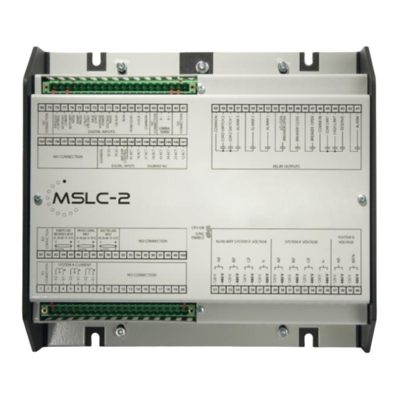
Connections27
-
Power Supply28
-
Interfaces48
-
Overview Pages115
-
Remote Base Load129
-
Introduction136
-
Operating Modes136
-
Voltage Matching152
-
Ramping155
-
Voltage Setpoint157
-
Breaker Close158
-
Introduction159
-
Base Load Mode159
-
Remote Control160
-
Utility Unload160
-
Local Unload161
-
Introduction162
-
Var Control163
-
Introduction164
-
Description164
-
Introduction167
-
Description167
-
Address Range180
-
Visualization181
-
Configuration182
-
Introduction211
-
Parameter List212
Advertisement