
Related Manuals for LeCroy SATASuite


Summary of Contents for LeCroy SATASuite
- Page 1 ROTOCOL OLUTIONS ROUP 3385 S COTT , CA 95054 ANTA LARA LeCroy SATASuite User Manual for SATracer and SATrainer Systems User Manual Version 6.26 For Software Version 6.26 September 2009...
- Page 2 The information in this document has been carefully checked and is believed to be reliable. However, no responsibility can be assumed for inaccuracies that may not have been detected. LeCroy reserves the right to revise the information in this document without notice or penalty. Trademarks and Servicemarks LeCroy, CATC, SATASuite, SATracer, SATrainer, SATracker, InFusion, and BusEngine are trademarks of LeCroy.
-
Page 3: Table Of Contents
Software Overview Starting the SATASuite Program ......25 Opening Sample Traces ....... 25 Tool Tips. - Page 4 Version 6.25 SATASuite User Manual Chapter 4 SATracer Recording Options General Recording Options ......44 Recording Type .
- Page 5 SATASuite User Manual Version 6.25 Creating Event Sequences ......75 States......... . . 75 How to Create an Event Sequence .
- Page 6 Generating Traffic ........154 Creating a Traffic Generation File with SATASuite ..154 Opening a Traffic Generation File .
- Page 7 SATASuite User Manual Version 6.25 Working with Generation Files ......167 Generating Traffic ........168 Stop Traffic Generation .
- Page 8 Version 6.25 SATASuite User Manual Command Log File Reports ......214 Exporting Command Log Files......215 Working with Exported Data Files .
-
Page 9: Overview
SATA frame headers and addresses, and start or stop recording based on user-defined events. The modular LeCroy SATA products allow users to expand and upgrade systems as their needs change. Adding new modules, or adding new BusEngines to existing modules, can economically expand the system capabilities while maintaining a common software interface through the integrated SATASuite Application Software. -
Page 10: General Description
The CATC 10K, in turn, connects to a PC over a Hi-Speed USB cable. The PC functions as the host controller for the CATC 10K. SATASuite software on the PC controls and configures the products and retrieves and displays recorded data. - Page 11 The SATASuite software provides powerful search functions that enable investigation and highlighting of specific events. In addition to immediate analysis, you can print any part of the data.
-
Page 12: Features
Protect your investment with industry-leading warranty LeCroy BusEngine LeCroy’s BusEngine™ Technology is at the heart of the SATA Product Line. The revolutionary BusEngine core uses FPGA technology and incorporates both the real-time recording engine and the configurable building blocks that implement data/state/error detection, triggering, external signal monitoring, and event counting and sequencing. - Page 13 SATASuite User Manual Version 6.25 Power Cord Set Cord Manufacturer and Models: 180-0005-00 Quail 5000.079 UL,CSA 180-0013-00 Quail 8500.098 VDE, KEMA, CEBERC, NEMDO, DEMDO, SETI, OVE, SEV 180-0014-00 Quail 9650.098 ASTA SATA Protocol Analyzer and Exerciser on the CATC 10K Platform CATC 10K is a USB 2.0 Certified Hi-Speed Device.
- Page 14 Version 6.25 SATASuite User Manual LeCroy Corporation...
-
Page 15: Installation
Please consult the readme file on the installation CD for the latest PC requirements. Analyzer Hardware Description LeCroy’s SATA Analyzer System is based on the CATC 10K platform. Plug-in modules for SATA are available with either the Internal SATA style cable connector (SS002MAA-X &... -
Page 16: Analyzer Led Descriptions
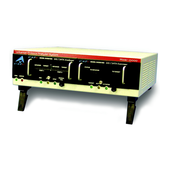
CATC 10K. Warning! Do not open the CATC 10K enclosure. There are no user serviceable parts inside. Refer servicing to LeCroy. Figure 2: Front Panel (Internal single lane connector - SS002MAA & SS003MAA-X) -
Page 17: Rear Panel Description
This connector links the analyzer to the Host PC. for the purpose of transmitting commands from the PC to the analyzer and uploading traces from the analyzer’s recording memory to the SATASuite software for viewing and analysis. RS-232 25 pin "Data Output" Connector This connector links a 25 pin RS-232 cable to an external breakout board. -
Page 18: Setting Up The Analyzer
Step 6 Follow Windows on-screen Plug-and-Play instructions for the automatic installation of the analyzer as a USB device on the Host PC (the required USB files are included on the SATASuite CD). Step through the Windows hardware wizard. The wizard will see that the CATC 10K has an internal USB hub and will begin loading hub drivers. -
Page 19: Connecting Devices To The Analyzer
Only one pair of connectors may be used at a time. Note: User’s with model SS004MAA-X must switch between "repeater" and "non-intrusive" using the SATASuite software. Go to Setup > Probe Control to enable "repeater" or "non-intrusive" mode. Figure 5: Plug-in Module SS004MAA-X offers two types of probing... - Page 20 Version 6.25 SATASuite User Manual Repeater Tap In repeater mode, the analyzer reproduces the exact patterns it receives on the inbound (RX) line. While the repeater does not re-time the signal—it does "clean-up" normal reflections that can occur over a full length cable when the analyzer is not in the line.
- Page 21 SATASuite User Manual Version 6.25 Figure 9: Test Setup With DUT Requiring External 4 Lane Connector Note: When using new External Connector Module (SS004MAA) with standard 4X External InfiniBand style cables, there is no need to use "cross-over" cable. Both cables above are straight.
- Page 22 Version 6.25 SATASuite User Manual LeCroy Analyzer with Internal SATA Connectors (SS002MAA & SS003MAA) When using original single-lane "SATA-style" module (SS002MAA & SS003MAA) with devices that utilize single-lane SATA style connectors, the special octopus cable must be used. The SATA connector side of the octopus cables would be attached to the analyzer (see Figure 10).
-
Page 23: Installing The Satasuite Software
SATASuite User Manual Version 6.25 Installing the SATASuite Software Once the SATA Analyzer has been recognized as a USB device, install the SATASuite software on the Host PC. Step 1 On the PC, run setup on the installation CD and follow the on-screen instructions. -
Page 24: Making A Recording On The Satracer Analyzer
Version 6.25 SATASuite User Manual Making a Recording on the SATracer Analyzer After installation, the software is configured to make a four-Mbyte snapshot recording of your Serial ATA traffic. To make this recording, follow these steps: Step 1 Connect a cable to each of the two connectors on the SATracer module, then connect the other ends to the Serial ATA device under test and Serial ATA host system. -
Page 25: Interrupting The Upload Process
SATASuite User Manual Version 6.25 Interrupting You can interrupt the upload process by pressing the Stop button. Pressing Stop the Upload will cause the following dialog box to open: Process This dialog presents options for stopping, continuing, or aborting the recording: •... -
Page 26: Saving The Trace
Version 6.25 SATASuite User Manual Saving the When the recording session is finished, the bus traffic is uploaded to the PC and is Trace automatically saved to the hard drive as a file named data[sn].sata where [sn] is the serial number of the 10K chassis; or the name you assign as the default filename. -
Page 27: Probe Control Settings
Version 6.25 Probe Control Settings LeCroy analyzers are designed to interface with the communications channel in a non-intrusive manner, to minimize any distruption of traffic or error conditions due to insertion of the analyzer. In some cases, the user may desire to adjust the probe settings to achieve a more optimum balance of complete data capture with minimal traffic disruption, and for that reason direct user access is provided to the probe control settings. - Page 28 Version 6.25 SATASuite User Manual Selecting this option displays the Probe Control Setting dialog: Allowed adjustments include chip selection, port selection, applying input signal equalization, output pre-emphasis, output power, input state, input LOS, and output state. You can Restore Factory Defaults.
- Page 29 SATASuite User Manual Version 6.25 Input Signal Equalization Input signal equalization can be adjusted within a matrix of three time values, with four settings for each time value. The time settings are relative: Short, Medium, and Long. The available levels, from left to right, are Off, Min(imum), Mod(erate), and Max(imum). The default setting is Min for Short.
- Page 30 Version 6.25 SATASuite User Manual Input State You can Terminate to VDD. Input LOS You can set LOS Threshold from 0 to 7. The default value is 2. Output State You can set the Mode from 0 to 15. The default value is 5.
-
Page 31: Sastracer Systems
SATASuite User Manual Version 6.25 SASTracer To access probe control settings for a SASTracer System, select Probe Control from the Systems Setup menu. If there’s more than one analyzer connected, the user will have an option to select Probe Control... - Page 32 Version 6.25 SATASuite User Manual High Swing - Alters the repeaters differential output swing to accommodate for PCB / connector loss. By default, the repeater uses "Normal" swing. "High" swing may be required when tapping between long backplanes or extended cable distances: •...
-
Page 33: Software Overview
Version 6.25 Chapter 3: Software Overview SATASuite is an application that may be used with or without an analyzer unit. When used without an analyzer, the program functions as a viewer to view, analyze, and print captured traces (from SATracer analyzers) or command log files (from the SATracker option on the SATracer). -
Page 34: Tool Tips
Version 6.25 SATASuite User Manual Tool Tips Throughout the application, Tool Tips provide useful information about buttons on the toolbar. To display a Tool Tip, pause the mouse pointer over an item of interest such as part of the trace or a button. -
Page 35: The Menu Bar
Convert .stg to .ssg - Converts SATA traffic generation files created by SATracer (.stg) to the SASTracer generation format (.ssg). Merge Trace Files Merges files which have been recorded as multitrace files (e.g., when using cascaded analyzers) Exit Exits the SATASuite program. LeCroy Corporation... - Page 36 Version 6.25 SATASuite User Manual Menu Function Setup … Display Options Opens a dialog for customizing trace colors, formats, and filters. Recording Options Configures the SASTracer analyzer’s recording behavior. Opens … (UPAS 10K) a dialog for selecting event triggers and filters, and for setting the size of the recording buffer and other recording options.
- Page 37 SATASuite User Manual Version 6.25 Menu Function Tracker Start Tracking Initiates tracking of all commands issued and completed. Stop Tracking Stops command tracking. Tracker Options Opens a dislog box to allow the user to establish settings to control command tracking and set the timeout trigger.
- Page 38 Version 6.25 SATASuite User Manual Menu Function View Toolbars Displays list of available Tool bars. Analyzer Network Opens a dialog that allows users to conduct chat sessions over Chat Bar an IP LAN. In order to send and receive electronic text messages, each user must be working with a PC that is on an IP LAN and also attached to an analyzer.
- Page 39 Online Check for Updates Use the Internet to analyze your system for licensed updates. Display License Opens a dialog box with information about the current status of Information ... the analyzer's license About... Displays version information about SATASuite. LeCroy Corporation...
-
Page 40: Toolbar
SATASuite User Manual Toolbar The Tool Bar provides quick access to most of the SATASuite software functions. You can learn the function of each button by pausing the mouse pointer over them. Descriptions of the buttons appear on the status bar at the bottom of the window and as tooltips above each button. - Page 41 SATASuite User Manual Version 6.25 Reports Buttons File Information Report. Opens a Traffic Summary. Opens a window summary of the trace file including displaying a table summary of traffic when it was made, the Recording recorded in the trace. Options used to create the file, and data on the analyzer that recorded the trace.
- Page 42 Version 6.25 SATASuite User Manual Multisegment Trace File Buttons These buttons become active if a multi-segmented trace file has been opened. Multi-segment traces are traces that have been recorded as a series of small segments rather than as a single, large recording. Multi-segmenting was developed to make it easier to work with large recordings where navigation can sometimes be difficult.
-
Page 43: Pop-Up Menus
SATASuite User Manual Version 6.25 Pop-Up Menus Pop-up menus within the trace provide options for formatting the trace. Left Mouse Button - Opens a menu for expanding fields, viewing data fields, and formatting the trace. The menu is context-sensitive and changes depending on what field of the data file has been clicked. -
Page 44: Status Bar
Version 6.25 SATASuite User Manual Status Bar The Status Bar is located at the bottom of the main display window. Depending on the current activity, the bar can be divided into as many as four segments. Recording When you begin recording on a SATracer Analyzer, the left-most segment of the Status... -
Page 45: Recording Status
SATASuite User Manual Version 6.25 Recording During recording, the current recording status is displayed in the next segment of the Status status bar. (Refer to previous screenshot for examples.) When recording is begun, one of the following messages flashes (depending on the selected Recording Options): •... -
Page 46: Navigation Tools
Version 6.25 SATASuite User Manual Navigation Tools You can zoom in and out, and wrap the recording to fit within the screen by using the following buttons: Zoom In Increases the size of the displayed elements, allowing fewer (but larger) Frame fields per screen. -
Page 47: Set Marker
SATASuite User Manual Version 6.25 Set Marker The Set Marker feature allows Frames to be marked so they can be navigate back to events of interest. Markers also provide you with a way of tagging events so you can perform timing calculations between them. - Page 48 Version 6.25 SATASuite User Manual Step 3 Enter your comment. Step 4 Click OK. A marked Frame is indicated by a vertical red bar along the left edge of the Frame # block: LeCroy Corporation...
-
Page 49: Edit Or Clear Marker
SATASuite User Manual Version 6.25 Edit or Clear Marker To clear or edit comments associated with a Frame marker, Step 1 Click on Frame # for the chosen packet. Step 2 To edit the marker comment, select Edit Marker. The Edit Marker for Frame # comment window appears. -
Page 50: Timing Calculations On Markers
Version 6.25 SATASuite User Manual Timing Calculations on Markers Markers can be used as reference points to calculate timing between events. To perform a timing calculation, select Reports > Timing Calculations, and then click the Markers buttons to select the markers you want to use for the calculation. Afterwards, click Calculate to calculate the timing between the marked events. -
Page 51: Satracer Recording Options
SATASuite User Manual Version 6.25 Chapter 4: SATracer Recording Options The Recording Options dialog box presents options for configuring a trace recording. The dialog box has two pages of options: General and Speed Selection. The General page present general types of options that affect all recordings. The Speed Selection page presents options for configuring the traffic speed that will be recorded. -
Page 52: General Recording Options
Two sets of Recording Type options are presented: Recording Scope and Recording Type. Recording The Recording Type box presents three options that control how SATASuite begins and Type ends a recording. The options are Snapshot, Manual Trigger, and Event Trigger. -
Page 53: Convention-Al Single Buffer Recording
SATASuite User Manual Version 6.25 Convention- In a Conventional recording, the entire trace is recorded and stored in the analyzer buffer al Single before it is uploaded to the host PC. Recordings are thus limited in size to the size of the Buffer analyzer buffer - or 2 GB. -
Page 54: File Structure For Segmented Files
Structure the index file is dataXYZ.smt, where XYZ is the last three digits of the analyzer’s serial number. (You can see the unit’s serial number by selecting Help > About SATASuite) Segmented Thus, for example, if you had an analyzer with the serial number 111, the index file would Files be called data111.smt. - Page 55 SATASuite User Manual Version 6.25 The index file looks something like a trace file but contains packet-like entities that summarize each 10 MB segment. When uploading is complete, the index file will be opened. Each "packet" in this file corresponds to one of the numbered segments. Double clicking on the packet will open the corresponding segment file.
- Page 56 Version 6.25 SATASuite User Manual Spooled Recording In a Spooled recording, uploading commences when the recording is begun. As traffic is uploaded from the analyzer to the host PC, the analyzer memory is freed - creating space for recording additional traffic. Recording can thus continue for long periods of time, and create file lengths well in excess of 2 GBs.
-
Page 57: Channel Settings
SATASuite User Manual Version 6.25 Channel Settings The Channel Settings page lets you to set speed, descrambling and packing options for each channel. It also lets you inhibit channel recording. Speed The SATracer system supports Autodetect Link Rate which is designed to pass through... -
Page 58: Recording Rules
Version 6.25 SATASuite User Manual Recording Rules The Recording Rules page lets you set triggers and filters. The page divides into following areas: • Toolbar - Contains buttons that control the Recording Rules page. • Available Events area -- Part of the screen where you can park buttons that you intend to use in the Global State Cell. -
Page 59: Recording Rules Toolbar
SATASuite User Manual Version 6.25 Recording Rules Toolbar The Recording Rules toolbar exposes functionality for controlling the Recording Rules page. New Event. Opens a menu of events. Selecting an event causes an event button to appear in the Available Events area. -
Page 60: Recording Rules Page - How It Works
Version 6.25 SATASuite User Manual Recording Rules Page - How it Works The Recording Rules page can be thought of as a chalk board where you create a graphical model of the events and actions. In essence, you are creating a visual representation of the rules that the analyzer should follow during a recording. -
Page 61: Assigning An Action
SATASuite User Manual Version 6.25 Assigning an Action Assigning an action tells the analyzer what to do when it has found the targeted event. If you do not assign an action, the analyzer will look for the event but do nothing once the event has been encountered. - Page 62 Version 6.25 SATASuite User Manual There can be up to 255 events linked together into a sequence. Only one sequence can be created. When two or more events have been moved into a Sequence cell, they can be linked into a sequence by assigning the action Advance the sequence to events in the chain.
- Page 63 SATASuite User Manual Version 6.25 Assigning an Action via the Properties Dialog Box Step 1 You can also assign actions to event buttons via the Properties dialog box. Double-click on an event button to open the properties dialog box. Step 2 Select the Actions tab.
-
Page 64: Types Of Pop-Up Menus
Version 6.25 SATASuite User Manual Types of Pop-up Menus The pop-up menu are context-sensitive and will display different options depending on the object you have clicked. Global State If you click on the Global State Cell or Sequence Cell (but not one of the buttons inside... -
Page 65: Action Pop-Up Menu
SATASuite User Manual Version 6.25 Action If you click on an Action button, you will get the following pop-up menu: Pop-up Trigger - Sets or clears Trigger action. Menu Filter In - Sets or clears Filter In action. This option precludes the use of Filter Out. - Page 66 Version 6.25 SATASuite User Manual Restart All - Restarts any sequences or counts you may have set on other buttons. The example on the right illustrates how the Restart All action works. This example reads "Look for a sequence of five SSP Frames and then trigger. If, however, an Error occurs any time before the fifth SSP frame has occurred, restart the count".
-
Page 67: New Events Menu
SATASuite User Manual Version 6.25 New Events Menu To add new Event buttons to the Available Events area, click the New Events button. A menu opens with the following categories: • Primitives • • ATA Commands • Data Pattern •... -
Page 68: Types Of Properties Dialog Boxes
Version 6.25 SATASuite User Manual Types of Properties Dialog Boxes Each cell and button has a properties dialog box that allows refinement of the options being set. Properties dialog boxes can be opened by: • Double-clicking a button or cell. - Page 69 SATASuite User Manual Version 6.25 Pin Button - Allows you to "pin" the Properties dialog box to the application so that it does not go away when another object appears such as an event, state or action. Description String - This area contains a textual description of the event.
- Page 70 Version 6.25 SATASuite User Manual The Pattern Editor has two components: the text boxes themselves, in which a pattern can be entered, and pull-down menus. Pull-down menus are available for some fields. By clicking on any field header, users will either be presented with a drop down menu (below) or they can enter values in decimal or hex and the string will be converted to binary after clicking on a different field.
-
Page 71: Event Properties Dialog Boxes - Descriptions
SATASuite User Manual Version 6.25 Event Properties Dialog Boxes - Descriptions Each Event button has a different Properties dialog box and each Properties dialog box has a different set of options. This section describes the Event Properties dialog boxes and their options. -
Page 72: Primitives
Version 6.25 SATASuite User Manual Primitives There are two types of primitive events: Primitive Categories and Primitives. Primitive Presents options for triggering or filtering on various Primitive categories. If NOT is Categories checked, any unchecked primitive category will generate an event match. -
Page 73: Sata Fis
SATASuite User Manual Version 6.25 SATA FIS There are ten SATA FISs that can be selected from the New Events menu: Register Host to Device, Register Device to Host, Set Device Bits, DMA Setup, BIST Activate, PIO Setup, Data, Route, and Vend FIS: 0xFF. -
Page 74: Ata Commands
Version 6.25 SATASuite User Manual ATA Commands ATA Commands are presented in a single dialog box. Presents several options: Commands Commands - Presents a long list of ATA Commands. Selecting a command will cause Properties the analyzer to search for the selected command. -
Page 75: Atapi Commands
SATASuite User Manual Version 6.25 ATAPI Commands Individual ATAPI 6/7 commands can be selected as a trigger event. Resource limitations restrict ATAPI triggering to a single channel and to a single ATAPI event. ATAPI To specify ATAPI commands as the recording event, select the command using the Command Operation Code or Command name. -
Page 76: Errors
Version 6.25 SATASuite User Manual Errors Errors are presented in a single dialog box. Errors Select from the checkboxes to specify the type(s) of errors you want the analyzer to Properties search for. If NOT is checked, any unchecked primitive will generate an event match. -
Page 77: State Properties Dialog
SATASuite User Manual Version 6.25 State Properties Dialog The State Properties dialog allows you to specify the Global state’s caption. To access this dialog box, click in the Global State Cell (but not on an Event button). Timer Specify the value for the timer in seconds, milliseconds, microseconds, and Properties nanoseconds. -
Page 78: Actions Tab In The Properties Dialog
Version 6.25 SATASuite User Manual Actions Tab in the Properties Dialog The Actions tab at the top of Event Properties dialog boxes lets you set the type of action that the analyzer will perform once an event has been found. - Page 79 SATASuite User Manual Version 6.25 The following table shows the types of Actions you can select. Action Comment Triggers the end of the recording. The end point of the recording is TRIGGER determined by the buffer settings in the Recording Options General page.
-
Page 80: Setting Conditions: The Role Of The Global State Cell
Version 6.25 SATASuite User Manual Setting Conditions: The Role of the Global State Cell The Global State cell is the arena in which you create triggering and/or filtering conditions. The cell is called the Global State cell because the conditions you create are active at all times. -
Page 81: Filter In And Filter Out
SATASuite User Manual Version 6.25 Creating Multiple Event Conditions in the Global State Cell When multiple buttons are placed in the Global Cell, it creates an "AND" condition or an "OR" condition depending on the actions selected. Creating an OR Condition - When two or more buttons in the Global State cell are assigned the same action, the analyzer will search for all of the events and perform the action on which ever event it sees first. -
Page 82: Filter In Or Out Everything
Version 6.25 SATASuite User Manual Filter In or The options Filter Out Everything or Filter In Everything allow you to filter all traffic in or out of the trace. These options are intended for a future release to allow you to Everything selectively exclude and include traffic from a recording. -
Page 83: Creating Event Sequences
SATASuite User Manual Version 6.25 Creating Event Sequences Event sequences are chains of events leading to some action. A sequence is a multi-event "if, then" condition: "If x followed by y followed by z occurs, trigger." Event sequences are created by dragging two or more buttons into the Sequence cell. The Sequence cell is a faintly marked cell just below the Global State cell. -
Page 84: How To Create An Event Sequence
Version 6.25 SATASuite User Manual How to To create an event sequence, you drag event buttons to the Sequence cell, link them Create an with the action Advance the Sequence, then apply a trigger or other action to the end of Event the chain. - Page 85 SATASuite User Manual Version 6.25 Step 7 Close the Properties dialog box by clicking the X in the top right corner. The Properties dialog box closes. Step 8 Drag the second event button to the cell immediately below the cell occupied by your first event button.
-
Page 86: Using A Timer
Version 6.25 SATASuite User Manual Step 13 Select Trigger. A cell will appear to the right of the second button saying "Trigger." Your sequence configuration is now complete and should look like this: Using a Timers let you set a time-delay for a trigger or other action. The following example Timer illustrates how timers work. - Page 87 SATASuite User Manual Version 6.25 Step 8 Select Specify Action(s). A sub-menu opens. Step 9 Select Advance the Sequence. The menu closes and an arrow appears that connects this cell to the State cell below. Step 10 Right-click on the Timer button. A pop-up menu appears.
- Page 88 Version 6.25 SATASuite User Manual Sequential Events and Timers The recording option above shows an example of using a Loop and Timer to trigger on Open Timeout violation. This reads "Wait for an OPEN ADDRESS on I1; If OPEN ACCEPT or an OPEN REJECT occurs on T1 within 1ms, restart the loop; ELSE IF 1 ms elapses (without detecting an OPEN ACCEPT or an OPEN REJECT on T1) then trigger the analyzer".
-
Page 89: Recording Options - Channels
SATASuite User Manual Version 6.25 Recording Options - Channels The Channels page allows the channel names to be customized. To change a channel name, select the channel, then click the edit button and enter the new text, then click OK. - Page 90 Version 6.25 SATASuite User Manual Custom Channel Names in the Trace - Custom channel names do not appear right away in the trace: the original names continue to display. To see the custom channel names, click in the first cell of the trace (the channel cell) and select Format from the pop-up menu, then select Custom.
- Page 91 SATASuite User Manual Version 6.25 Custom Channel Names in the Bus Usage Window - Custom Channel names automatically appear in the Bus Usage window as soon as they have been customized. The easiest way to see this is to open the Bus Usage window and then to open the Properties dialog for the window.
- Page 92 Version 6.25 SATASuite User Manual LeCroy Corporation...
-
Page 93: Display Options
SATASuite User Manual Version 6.25 Chapter 5: Display Options Use the Display Options menu to specify the way data file information is displayed. From the Setup menu, select Display Options. LeCroy Corporation... -
Page 94: General Display Options
Version 6.25 SATASuite User Manual General Display Options Use the General Display Options to specify the basic appearance of a view. • Zoom Level: Adjustable in discrete increments from 10% to 200% percent. • Enable Tips: Select to enable Tool Tips with explanation text to pop up when you position your cursor over various fields in the Trace View. -
Page 95: Setting Color, Formatting, And Hiding Options
SATASuite User Manual Version 6.25 Setting Color, Formatting, and Hiding Options Click the Color/Format/Hiding tab on the Display Options screen. Use this window to customize the colors and formats associated with each field in the Trace view. You can also use this window to hide fields within the trace. -
Page 96: Changing Field Formats
Version 6.25 SATASuite User Manual You can also customize the colors by using the options in the Custom tab. Changing To change field formats, select an item under the Group and Color column. This action Field will enable the formats radio buttons on the right. The format types change with respect Formats to the item selected under the Group and Color column. -
Page 97: Hiding Display Options
SATASuite User Manual Version 6.25 Hiding To hide one or more fields in the trace, select the appropriate item Display from the Group and color column, click the checkbox marked Hidden, Options and click the Save button. You can also hide Frames from a trace by selecting the desired options from the checkboxes. -
Page 98: Saving Display Options
Version 6.25 SATASuite User Manual Saving Display Options To complete your display options settings, use the features at the bottom of the Display Options window. These features remain the same no matter which of the four Display Options windows you are working in. -
Page 99: Reading A Recording
SATASuite User Manual Version 6.25 Chapter 6: Reading a Recording Recording View Features SATA Suite viewing software displays make extensive use of color and graphics to fully document the captured traffic. Frames (for SA Tracer files) or commands (for SA Tracker files) are shown on separate time-stamped rows, with their individual fields both labeled and color coded. - Page 100 Version 6.25 SATASuite User Manual Frame Layer Frame Level view is the default decode level. Frame Level view displays traffic as shown below: FIS Layer When you click the FIS button, the FIS Layer traffic is decoded and presented as shown below.
- Page 101 SATASuite User Manual Version 6.25 OOB (Out of Band) Signaling View The OOB view combines OOB scenarios (establishing link, speed negotiation, etc.) into a simplified and integrated view. These scenarios typically occur at power on and after hardware resets as devices initialize and initiate communications.
- Page 102 Version 6.25 SATASuite User Manual As with other views, you can get additional information on the event by holding your mouse over selected fields or you can "open" any decode level to reveal the components by clicking the small triangle in the upper left corner of the cell.
- Page 103 SATASuite User Manual Version 6.25 Setting Hierarchical View Level Using the Display Options Window You can also set the hierarchical view by selecting checkboxes in the Trace Viewing Level Options in the Display Options window. LeCroy Corporation...
-
Page 104: View Raw Bits
Version 6.25 SATASuite User Manual View Raw Bits SA Tracer allows you to view low-level 8B/10B values for SATA traffic. You can expand a specific Frame to view the raw bits by right clicking on the Frame number and selecting Show Raw Bits. -
Page 105: Running Disparity
SATASuite User Manual Version 6.25 Navigation - To move to the previous or next packet in the trace, click one of the two buttons at the bottom of the window: • Prev - Displays data for the previous Frame in the trace. -
Page 106: Expanding A Data Payload
Version 6.25 SATASuite User Manual Expanding a You can expand a Data Payload field to view it in greater detail or collapse it when you Data want a more compact view. SATA Suite allows you to expand and collapse the data... -
Page 107: View Data Block Window
SATASuite User Manual Version 6.25 View Data Block Window The View Data Block command opens a dialog box that lets you display and navigate the data within Frames and Transport Layer transactions. This dialog box gives you several format choices for the data: binary, hexadecimal, ASCII and decimal. It also gives you the ability to navigate through data fields within different Frames and Transport Layer transactions. -
Page 108: Incomplete Frames Handling And Display
Version 6.25 SATASuite User Manual The menu presents three scrolling options: • Update only on request - Locks whatever data block currently is on display in the Data window unless overridden by a direct request. There are two ways to make a request -- by clicking on the buttons or by right-clicking in the trace on a data block and selecting View Data Block from the pop-up menu. - Page 109 SATASuite User Manual Version 6.25 When incomplete frames are displayed, no field decoding takes place, only the raw payload recorded for the incomplete frame is presented. However, in the Link Tracker some field decoding can be performed, if possible (part of the frame header is received intact).
-
Page 110: Split Frames
Version 6.25 SATASuite User Manual Split Frames Some frames - mostly STP (SATA) - can take a very long time on the bus. For SATA frames it happens when Host and target go into long Hold periods while writing or reading the data. -
Page 111: Compact View
SATASuite User Manual Version 6.25 In the example above, although SATA frames both on Transmitter and Receiver sides are split, they are assembled together in the Transport Layer transaction. The payload, that was split into 6564 and 1632 bytes is assembled together in one 8192 bytes buffer. - Page 112 Version 6.25 SATASuite User Manual When View>Compact (or Ctrl-Q) is selected, the trace file is now shown as follows, which allow far more data to be displayed in the same screen: LeCroy Corporation...
- Page 113 SATASuite User Manual Version 6.25 Note that the occurance of just one frame in the display with a different header ("Idle" instead of "Time Delta") results in the header row being redisplayed. LeCroy Corporation...
-
Page 114: Export Options
Version 6.25 SATASuite User Manual Export Options Trace data captured by SA Tracer can be exported for other uses, including uses outside the system. These options are accessed through the File menu by selecting Export, as shown below. There are four export options supported. The data fields which will be present in the exported files are determined by the current screen view. -
Page 115: Packets To Text (Packet View Format)
SATASuite User Manual Version 6.25 Packets to This option is used to create a text version of the trace (e.g., for use when emailing a trace Text (Packet section). Selecting this option brings up a screen to allow you to define the range of View events that you want to include in the text file. - Page 116 Version 6.25 SATASuite User Manual Select the destination folder and enter the destination filename for the exported data. Select the layer to export (either Transport or ATA Application Layer). Indicate whether you would like hidden packets to be included in the exported file or just displayed packets.
- Page 117 SATASuite User Manual Version 6.25 LeCroy Corporation...
- Page 118 Version 6.25 SATASuite User Manual LeCroy Corporation...
-
Page 119: Searching Recordings
SATASuite User Manual Version 6.25 Chapter 7: Searching Recordings SATA Suite has several search commands that enable you to navigate a recording in search of key events such as errors and triggers. These commands are launched from the Search menu. -
Page 120: Go To Marker
Version 6.25 SATASuite User Manual Go to Marker To instruct the Analyzer to display a marked Frame, follow these steps: Step 1 From the Search menu, select Go to Marker. Step 2 Select the desired Frame from the displayed list. -
Page 121: Go To
SATASuite User Manual Version 6.25 Go To The Go To feature takes you directly to an event in a recording by allowing you to search by a specific criteria. Only the items present in a recording will be displayed in the Go to menu. -
Page 122: Find
Version 6.25 SATASuite User Manual Find Find is a utility for conducting searches of one or more events within a recording. In SA Tracer trace files, Find allows you to search different hierarchical levels within the trace - Frames, Transactions, SCSI Operations, and Mgt Transactions. To start find, •... -
Page 123: Complex Searches
SATASuite User Manual Version 6.25 Right area -- Controls the specific events to be searched within the trace. The box in this right section displays events from the selected Event Group. The right area is context sensitive - the Event Group selected in the Center Area determines what types of events display on the right. -
Page 124: Using Find
Version 6.25 SATASuite User Manual Using Find Step 1 Select the display level to be searched from the Search For box on the left side of the window. For example, to search through Commands, select Commands. The display level affects options presented in the Events Group box. -
Page 125: Find Next
SATASuite User Manual Version 6.25 Find Next To apply the previous Find parameters to the next search, Select Find Next (or F3) under Search on the Menu Bar Click on the Tool Bar. When Link Tracker is open and Find Next is used, the software repositions the LinkTracker (and other views) on the next frame containing the same primitive. - Page 126 Version 6.25 SATASuite User Manual LeCroy Corporation...
-
Page 127: External Interface For Trigger In /Out
Version 6.25 Chapter 8: External Interface for Trigger In /Out With each CATC 10K analyzer, LeCroy includes two mechanisms for low latency communications with general purpose test and measurement equipment: • BNC Trigger in / out - This connection can be used to send clocking information and recording commands from one analyzer to another (see Setup for Cascaded Multiple Analyzer Use in Chapter 10). - Page 128 Version 6.25 SATASuite User Manual Step 3 Select the New Event button and specify the protocol level event desired to initiate the external Trigger Out signal Step 4 Under the Actions Tab, Select the type of External Trigger signal suitable for the external instrument. The 10K chassis support three external trigger-out signal types: •...
-
Page 129: Using The Bnc Trigger In
SATASuite User Manual Version 6.25 Using the Step 1 Attach an appropriate BNC Trigger Out connector on a general BNC Trigger purpose test instrument to the BNC Trigger In connector using the provided BNC cable. Step 2 In the SATA Suite software, under Recording Options, select the General Tab and click the radio button Event Trigger under Recording Type. -
Page 130: Breakout Board Trigger In / Out
Version 6.25 SATASuite User Manual Breakout Board Trigger In / Out The Breakout Board connects via a 25 pin serial interface cable to the Data In/Out connector located on the rear of the analyzer unit. Each signaling pin is isolated by a 100 Ω... -
Page 131: Pin-Outs For The Data In/Out Connector
SATASuite User Manual Version 6.25 Pin-Outs for the Data In/Out Connector The following table lists the pin-out and signal descriptions for the Data In/Out connector on a cable that connects to the Breakout board. Data In/Out Connector – Pin-Out Signal Name... -
Page 132: Prototype Rework Area
Version 6.25 SATASuite User Manual External Interface Breakout Board Prototype The Breakout Board contains a prototype rework area for making custom circuits for rapid Rework development. The area consists of plated-through holes, 20 columns wide by 27 rows Area long. The top row of holes is connected to GND and the bottom row is connected to +5V. -
Page 133: Configuring Input Signaling Through The Breakout Board
SATASuite User Manual Version 6.25 Configuring Input Signaling through the Breakout Board To configure the analyzer to trigger on an input signal from the breakout board, perform the following steps: Step 1 Select Setup > Recording Rules to open the Recording Options dialog. - Page 134 Version 6.25 SATASuite User Manual Step 6 Select Properties from the pop-up menu. The Properties dialog opens. Step 7 If you want to configure the analyzer to trigger on a specific bit pattern, enter it in the box marked Byte0. Alternatively, you can enter a hex pattern and mask into the boxes marked Mask and Match.
-
Page 135: Reports
SATASuite User Manual Version 6.25 Chapter 9: Reports The Report menu provides several reports to assist you in analyzing traffic recorded by the Analyzer. File Information To display data on a trace, select Report >File Information from the menu. The File Information dialog opens and provides information about the recording such as when it was made and version of the Analyzer Firmware and BusEngine. -
Page 136: Traffic Summary
Version 6.25 SATASuite User Manual Traffic Summary The Traffic Summary displays a report of traffic in the data file and appears at the bottom of the SATA Suite main window. The left side contains a tree view where you can expand or collapse types of data you want displayed to the right of the Traffic Summary window. -
Page 137: Error Summary
SATASuite User Manual Version 6.25 Error Summary The Error Summary button opens the Traffic Summary window and displays a list of errors analyzed throughout the recording. Step 1 From the Report menu, select Error Summary. The Traffic Summary window appears with Error information displayed. -
Page 138: Bus Utilization
Version 6.25 SATASuite User Manual Bus Utilization The Bus Utilization window displays information on bandwidth use. To open the Bus Utilization window, select Report >Bus Utilization or click the button marked . A window opens like the one shown below:... - Page 139 SATASuite User Manual Version 6.25 Bus Utilization Buttons The Bus Utilization window has a row of buttons for changing the format of the displayed data and for exporting data: The buttons have the following functions: Save As - Saves the...
- Page 140 Version 6.25 SATASuite User Manual View Settings Menu Clicking the View settings button causes a menu to open with options for formatting the display. • Orient Horizontally - changes the orientation of bus usage to horizontal. After selecting this option, the menu will say "Orient Vertically."...
- Page 141 SATASuite User Manual Version 6.25 Graph Areas Menu The Graph Areas menu allows you to view different information in the Bus Utilization window. Step 1 Click the button. The Graph Areas menu opens. Step 2 Select a graph type from the menu. Repeat for additional graphs.
- Page 142 Version 6.25 SATASuite User Manual Modifying the Appearance of Graphs To modify a Bus Usage graph, follow these steps below. Step 1 With a graph displaying in the Graphs Area, right-click anywhere in the graph and choose Properties from the pop-up menu.
-
Page 143: Link Tracker Window
SATASuite User Manual Version 6.25 Link Tracker Window The Link Tracker window displays a detailed chronological view of events. Events are shown on a primitive-by-primitive basis within columns within the window, each column represents a single upstream or downstream channel. Time is presented as rows. Idle time is shown by empty rows in the window. - Page 144 Version 6.25 SATASuite User Manual Link Tracker Buttons The Link Tracker window has a row of buttons for changing the format of the displayed data and for exporting data: The buttons have the following functions: Full Screen Show Values Synchronize Trace View.
- Page 145 SATASuite User Manual Version 6.25 View Options Menu Clicking the View Options button causes a menu to open with options for formatting the display. • Collapsible Idle Time - Opens a dialog box for setting the Idle time value. By setting a value, you tell the analyzer when to collapse Idle times and display them as grayed out strips within the Link Tracker window.
- Page 146 Version 6.25 SATASuite User Manual Setting Markers Markers can be set on any dword on any event within the Link Tracker window. To set a marker, right-click on an event, then select Set Marker from the pop-up menu. Once marked, events can be easily navigated to via the Go to Marker command in the Search menu.
- Page 147 SATASuite User Manual Version 6.25 Hiding Traffic You can hide Aligns, Channels and other data from the Link Tracker window by clicking the Hide buttons on the toolbar in the Trace window or by selecting one or more of the various Hide options in the Display Options dialog box.
- Page 148 Version 6.25 SATASuite User Manual Collapsing Idle Time, Enabling Tooltips, and Resetting Column Widths Click the View Options button to open a menu with options for formatting the display. Three options are presented: Collapsible Idle Time - Opens a dialog box for setting the Idle time thresholds. Setting a value tells the analyzer when to collapse Idle times and display them as grayed out strips within the Link Tracker window.
-
Page 149: Frame Tracker Window
SATASuite User Manual Version 6.25 Frame Tracker Window The Frame Tracker window displays a detailed chronological view of traffic on a Frame-by-Frame basis. Events are shown within columns within the window, each column representing a channel. Time is presented as rows. Idle time is shown by empty rows in the window. - Page 150 Version 6.25 SATASuite User Manual Frame Tracker Buttons The Frame Tracker window has a row of buttons for changing the format of the displayed data and for exporting data: The buttons have the following functions: Full Screen Zoom In Synchronize Trace View.
- Page 151 SATASuite User Manual Version 6.25 Calculating Time between Frames You can calculate time between cells within Frame Tracker by clicking on an event and then positioning your mouse pointer over a second event and reading the ensuing tooltip. Step 1 Click on the time value for the first event.
- Page 152 Version 6.25 SATASuite User Manual LeCroy Corporation...
-
Page 153: Chapter 10 Networking
SATASuite User Manual Version 6.25 Chapter 10: Networking SATA Suite has networking and cascading functions that are described in this chapter. • Cascading -- Allows two to four SA Tracer analyzers be linked (or "cascaded" ) together into a single, synchronized, logical unit in order to increase the number of ports that can be monitored. -
Page 154: Hardware Setup For Direct Usb Connections
Version 6.25 SATASuite User Manual Hardware Setup for Direct USB Connections Connecting multiple analyzers to a single PC by USB gives you the convenience of being able to control multiple analyzers from a single SATA Suite application. The application provides you with a means of toggling back and forth between the analyzers. -
Page 155: Set Up For Remote Access Over An Ip Lan
SATASuite User Manual Version 6.25 Set Up for Remote Access over an IP LAN Analyzers can be run remotely over an IP network. In an IP network, the analyzers connect their respective hosts via USB and the hosts, in turn, connect to each other via IP. -
Page 156: Configuring The Connection
Version 6.25 SATASuite User Manual Configuring the Connection Once you have completed the physical setup, you are ready to configure the analyzer connection. Configuration for two or more USB connected analyzers is minimal. Connected In the following example, two SA Tracer analyzers are linked via USB to a host PC. You Analyzers connect to one of the two analyzers. -
Page 157: Remote Analyzers Over An Ip Network
SATASuite User Manual Version 6.25 Remote To configure SATA Suite to remotely control an analyzer over an IP LAN, you will need to Analyzers use the Analyzer Network dialog to browse to the host controlling the analyzer and add Over an IP both the host and its PC to the dialog. -
Page 158: Configuring Cascaded Multiple Analyzers
Version 6.25 SATASuite User Manual Step 7 Select Setup > All Connected Devices ... to open the Analyzer Devices dialog box. Step 8 Uncheck all boxes except for the one for the remote analyzer that you wish to connect to. -
Page 159: Network Chat
SATASuite User Manual Version 6.25 Network Chat Analyzer Network Chat is a utility that allows users to conduct chat sessions over an IP LAN. In order to send and receive electronic text messages, each user must be working with a PC that is attached to an analyzer. - Page 160 Version 6.25 SATASuite User Manual LeCroy Corporation...
-
Page 161: Chapter 11 Traffic Generation With Satrainer
SATA Exerciser Hardware LeCroy SA Trainer requires both the SATA Analyzer module and the SATA Exerciser module that plugs into the right slot of the CATC 10K chassis. Installing the SATracer Exerciser module will require that you remove ports 3&4 (if equipped with a 4 port... -
Page 162: Setting Up Sata Exerciser For Target Emulation
Version 6.25 SATASuite User Manual Setting Up SATA Exerciser for Target Emulation Connect the cable from the SATA Exerciser To Initiator port to the Initiator-side port on the unit under test. This transmits the Traffic Generator stream from the To Initiator port on the SA Tracer/Trainer to the initiator-side port on the unit under test. - Page 163 SATASuite User Manual Version 6.25 Step 2 From the menu, select File>Export>to Generator File Format (.ssg). The Export to Generator Text screen appears (.ssg). There are several options . File Name - Enter a user-defined file name. Save As Type - There is but one option: SASTrainer Generator Files (.ssg).
-
Page 164: Opening A Traffic Generation File
Version 6.25 SATASuite User Manual Opening a Traffic Generation File Once the Traffic Generation file (*.ssg) file has been created, you can then open it in the SATA Suite application. To open a Traffic Generation file, Step 1 Select Open under File on the Menu Bar Click on the Tool Bar. -
Page 165: Starting The Script Editor
SATASuite User Manual Version 6.25 Starting the Script Editor To edit an .ssg file, use the Script Editor. The Script Edit is an editing tool that will display the .ssg file and its supporting Include files. To launch the Script Editor: click the Script Editor button on the toolbar or right-click in the trace window and choose Edit as Text. -
Page 166: Toolbar
Version 6.25 SATASuite User Manual Toolbar The toolbar contains buttons for saving your edits, navigating, searching and other functions. The buttons have the following functions: Save. Saves your edits and immediately updates the Go to next bookmark. setting bars and Frames shown in the trace window. -
Page 167: File Tabs
SATASuite User Manual Version 6.25 View Options Menu The View Options button has a menu with three options: • Enable Outlining - Adds an expandable/collapsible tree structure to the left side of the Script Editor showing the hierarchical relationship of the script lines. -
Page 168: Overview Of Generation And Global Settings Files
The include statements provide links to the Include files which, in turn, provide the definitions for primitives, frames, and "global settings" - i.e., settings that hold for most or all of the generation session. The definitions for SATA traffic are contained in five LeCroy-provided Include files: Settings.inc, PrimitivesDecl.inc, AddressFramesDecl.inc, SSPFrames.inc, SMPFrames.inc and SSPFrames.inc. -
Page 169: Settings.inc File
SATASuite User Manual Version 6.25 Settings.inc The Settings.inc file contains global statements about the link, the type of device being File emulated, and other conditions that are to exist throughout part or all of the traffic generation. This file must be included in the traffic generation file. - Page 170 Version 6.25 SATASuite User Manual Editing Settings.inc Text in the Settings.inc file can be edited directly or copied into the beginning of the traffic generation file and edited there. Many users opt for this latter approach. When editing global settings, keep in mind the following rule: •...
- Page 171 SATASuite User Manual Version 6.25 The Global Setting "AutoAlign" AutoAlign is a global setting that may be on or off depending on the type of device you are emulating. There is an AutoAlign setting for SAS and one for SATA - for example, "set AutoAlignSAS = ON"...
- Page 172 Version 6.25 SATASuite User Manual Placing Global Settings in the Generation Block Some global settings such as AutoAlign = On/Off can be set and reset in the generation block. For example, a user might want to set SASAutoAlign = ON prior to traffic generation and then have it change to OFF half way through the generation session.
-
Page 173: Primitive And Frame Definitions
SATASuite User Manual Version 6.25 While most global settings can be set in the generation block, three will be ignored if placed within the generation block: set Link Speed = set GenerationMode = set SSC = These commands should be configured either in the Setting.inc file or at the beginning of the traffic generation file as a global statement. -
Page 174: Primitives Decl.inc
Version 6.25 SATASuite User Manual 2. Data Length Fields can be fixed-length or variable - By default, data frames are of a fixed length. If you want to generate variable length frames, then place an asterisk in the Data definition field in the SSPFramesDecl.inc file: Data : * If you replace the asterisk with a value, then the field becomes fixed length. -
Page 175: Working With Generation Files
SATASuite User Manual Version 6.25 Working with Generation Files The easiest way to generate traffic is to start with one of the sample generation files and edit the settings to see how the script file behaves. As you make and save changes, the trace view of the generation file is automatically updated. -
Page 176: Generating Traffic
Version 6.25 SATASuite User Manual In the lower screenshot, global settings make up the eight bars at the top of the window. Below that are five frames. If you look at the script itself, you will see that there are six frame commands, five active and one commented out. -
Page 177: Chapter 12 Satrainer Generation Language
SATASuite User Manual Version 6.25 Chapter 12: SATrainer Generation Language The SA Trainer File Generation Language is an API that allows you to separate traffic into text commands. These commands are used construct primitives and frames that are sent to the host or the device. -
Page 178: Language
Version 6.25 SATASuite User Manual Language Comments: '#' - Comment symbol. The line remainder after this symbol will be ignored. '/*' '*/' - Comment Block. All the text between '/' '*' and '*' '/' is ignored. This is an example of a block of comments. -
Page 179: Data Patterns
SATASuite User Manual Version 6.25 Data Data patterns are streams of hexadecimal values. Using '['']' lets the user include Patterns constants or predefined data pattern in another pattern. XAMPLES DataPattern PATTERN_1 = AAAABBBB [SOME_HEX_DATA] EEEEFFFF 1210ABB1 AAAABBBB 1210ABB1 AAAABBBB 1210ABB1 AAAABBBB 1210ABB1 ["SOME DEC DATA"] 1210AB... -
Page 180: Packets/Frames
Version 6.25 SATASuite User Manual Packets/ Using the "Frame" or "Packet" keyword, user can define a frame of traffic to be used in Frames the generation stream. Declarations of prolog and epilog may be mixed with field declarations. Frame "name" : "parent name"... - Page 181 SATASuite User Manual Version 6.25 XAMPLES Primitive : * Primitive : SOF, 48 # where 48 = offset Primitive : "CLOSE (NORMAL)", 36, 5 # where 5 = repeat • Prolog and Epilog define Primitive chains to be used at the beginning...
-
Page 182: Generation Block
Version 6.25 SATASuite User Manual Frame Some_Frame_1 : Some_Frame Field32 = "Some Hex Data" Data = { 11111111 22222222 33333333 44444444 55555555 } Opcode : 128, 8, 0x2A : 64 Primitive : * Primitive : "CLOSE (NORMAL)", 24, 48 Prolog = "CHAIN (ONE)"... -
Page 183: Definitions
SATASuite User Manual Version 6.25 Definitions • Chain Definition: • Without any parameters, the chain is sent once • With "Repeat" and "Idle" parameters, the chain is sent N times and then nothing is sent (idle) M times. "Repeat" and "Idle" are optional. -
Page 184: Loops
Version 6.25 SATASuite User Manual Field16 = 0xEEEE # Example of the data payload assignment which uses both integer variables, constants, hex literals and data patterns Data = { y y y y 7a7a7a7a "Some Hex Data" "Some Hex Data" 8b8b8b8b... -
Page 185: Satrainer Generation Commands
SATASuite User Manual Version 6.25 SATrainer Generation Commands General Commands IDLE (n) Generator will insert n idle dwords into gen stream CLEAR_CREDIT_AVAIL This commands clears the credit established with the command WF_CREDIT_AVAIL. (See WF_CREDIT_AVAIL in following section on Wait Commands for explanation). -
Page 186: Sata Commands
Version 6.25 SATASuite User Manual SPEED_NEG_ALIGN0 Generator will go through SPEED_NEG_ALIGN0 stage of SAS SpeedNeg process using current SPEED_NEG_ALIGN0 settings. SPEED_NEG_ALIGN1 Generator will go through SPEED_NEG_ALIGN1 stage of SAS SpeedNeg process using current SPEED_NEG_ALIGN1 settings. SATA Look at STP sample file for syntax. -
Page 187: Primitive Commands
SATASuite User Manual Version 6.25 Primitive The following is a list of SAS and SATA primitives declared in "Primitives.Decl.inc" as Commands Symbol Chains. If you want to use these primitives in your script you must also include "Primitives.Decl.inc" in your script. - Page 188 Version 6.25 SATASuite User Manual • SATA_ERROR • AIP (NORMAL) • AIP (RESERVED 0) • AIP (RESERVED 1) • AIP (RESERVED 2) • AIP (RESERVED WAITING ON PARTIAL) • AIP (WAITING ON CONNECTION) • AIP (WAITING ON DEVICE) • AIP (WAITING ON PARTIAL) •...
- Page 189 SATASuite User Manual Version 6.25 • OPEN_REJECT (STP RESOURCES BUSY) • OPEN_REJECT (WRONG DESTINATION) • DONE (ACK/NAK TIMEOUT) • DONE (CREDIT TIMEOUT) • DONE (NORMAL) • DONE (RESERVED 0) • DONE (RESERVED 1) • DONE (RESERVED TIMEOUT 0) • DONE (RESERVED TIMEOUT 1) •...
-
Page 190: Wait Commands
Version 6.25 SATASuite User Manual Wait Syntax: WAIT_FOR { <command1> <command2> ... <group1> <group2> ... } Commands WaitCommand Name Description WF_TIMEOUT Timeout Credit Available When WF_TIMEOUT is requested in WAIT_FOR command the wait session will be released after timeout has elapsed. - Page 191 SATASuite User Manual Version 6.25 WaitCommand Name Description WF_CREDIT_AVAIL Credit Available This function is based on a 10-bit counter whose value can range from -512 to +511 (twos-complement). This counter is cleared by sending or receiving an OPEN_ACCEPT primitive, or by execution of a CLEAR_CREDIT_AVAIL command in the script.
- Page 192 Version 6.25 SATASuite User Manual WaitCommand Name Description WF_DONE_CREDIT_ primitive TIMEOUT WF_DONE_NORMAL primitive WF_DONE_RESERVED_0 primitive WF_DONE_RESERVED_1 primitive WF_DONE_RESERVED_ primitive TIMEOUT_0 WF_DONE_RESERVED_ primitive TIMEOUT_1 WF_ERROR primitive WF_HARD_RESET primitive WF_AIP_NORMAL primitive WF_AIP_RESERVED_0 primitive WF_AIP_RESERVED_1 primitive WF_AIP_RESERVED_2 primitive WF_AIP_RESERVED_WAIT primitive _ON_PART WF_AIP_WAIT_ON_CONN primitive...
- Page 193 SATASuite User Manual Version 6.25 WaitCommand Name Description WF_REC_RESOURCES_ Advanced Wait Condition A OUTPUT_A This command causes generation to wait for Event "A" to occur that you defined in the Generation Options dialog described at the end of this chapter.
- Page 194 Version 6.25 SATASuite User Manual WaitCommand Name Description WF_BLOCK1_MISC_ reserved RESERVED_4 WF_SATA_CONT primitive WF_SATA_DMAT primitive WF_SATA_EOF primitive WF_SATA_ERROR primitive WF_SATA_HOLD primitive WF_SATA_HOLDA primitive WF_SATA_PMACK primitive WF_SATA_PMNAK primitive WF_SATA_PMREQ_P primitive WF_SATA_PMREQ_S primitive WF_SATA_R_ERR primitive WF_SATA_R_IP primitive WF_SATA_R_OK primitive WF_SATA_R_RDY primitive WF_SATA_SOF...
- Page 195 SATASuite User Manual Version 6.25 WaitCommand Name Description WF_OPEN_REJECT_ primitive PROTOCOL_NOT_ SUPPORTED WF_OPEN_REJECT_ primitive RETRY WF_OPEN_REJECT_ primitive STP_RESOURCES_BUSY WF_OPEN_REJECT_ primitive WRONG_DESTINATION WF_OPEN_REJECT_ primitive RESERVED_ABANDON_0 WF_OPEN_REJECT_ primitive RESERVED_ABANDON_1 WF_OPEN_REJECT_ primitive RESERVED_ABANDON_2 WF_OPEN_REJECT_ primitive RESERVED_ABANDON_3 WF_OPEN_REJECT_ primitive RESERVED_CONTINUE_0 WF_OPEN_REJECT_ primitive RESERVED_CONTINUE_1 WF_OPEN_REJECT_...
- Page 196 Version 6.25 SATASuite User Manual WaitCommand Name Description WF_NOTIFY_ENABLE_ primitive SPINUP WF_NOTIFY_RESERVED_0 primitive WF_NOTIFY_RESERVED_1 primitive WF_NOTIFY_RESERVED_2 primitive WF_BROADCAST_ primitive CHANGE WF_BROADCAST_ primitive RESERVED_0 WF_BROADCAST_ primitive RESERVED_1 WF_BROADCAST_ primitive RESERVED_2 WF_BROADCAST_ primitive RESERVED_3 WF_BROADCAST_ primitive RESERVED_4 WF_BROADCAST_ primitive RESERVED_CHANGE_0 WF_BROADCAST_ primitive...
-
Page 197: Wait Command Groups
SATASuite User Manual Version 6.25 Wait Command Groups Wait Command Group Group Contents WF_TIMEOUT WF_TIMEOUT_BLOCK_ONE WF_TIMEOUT_BLOCK_TWO WF_ALL_SOF WF_SOF WF_SOAF WF_ALL_EOF WF_EOF WF_SOAF WF_NAK WF_NAK_CRC_ERROR WF_NAK_RESERVED_0 WF_NAK_RESERVED_1 WF_NAK_RESERVED_2 WF_RRDY WF_RRDY_NORMAL WF_RRDY_RESERVED_0 WF_RRDY_RESERVED_1 WF_CREDIT_OK WF_CREDIT_AVAIL WF_CREDIT_BLOCKED_RECEIVED WF_CLOSE WF_CLOSE_CLEAR_AFFILIATION WF_CLOSE_NORMAL WF_CLOSE_RESERVED_0 WF_CLOSE_RESERVED_1 LeCroy Corporation... - Page 198 Version 6.25 SATASuite User Manual Wait Command Group Group Contents WF_DONE WF_DONE_ACK_NAK_TIMEOUT WF_DONE_CREDIT_TIMEOUT WF_DONE_NORMAL WF_DONE_RESERVED_0 WF_DONE_RESERVED_1 WF_DONE_RESERVED_TIMEOUT_0 WF_DONE_RESERVED_TIMEOUT_1 WF_AIP WF_AIP_NORMAL WF_AIP_RESERVED_0 WF_AIP_RESERVED_1 WF_AIP_RESERVED_2 WF_AIP_RESERVED_WAIT_ON_PART WF_AIP_WAIT_ON_CONN WF_AIP_WAIT_ON_DEVICE WF_AIP_WAIT_ON_PARTIAL WF_REC_RESOURCES WF_REC_RESOURCES_OUTPUT_A WF_REC_RESOURCES_OUTPUT_B WF_REC_RESOURCES_OUTPUT_C WF_REC_RESOURCES_OUTPUT_D WF_REC_RESOURCES_OUTPUT_E WF_REC_RESOURCES_OUTPUT_F WF_RCV_STATUS WF_SATA_R_ERR WF_SATA_R_OK WF_PM_REQ WF_SATA_PMREQ_P WF_SATA_PMREQ_S...
- Page 199 SATASuite User Manual Version 6.25 Wait Command Group Group Contents WF_PM_STATUS WF_SATA_PMACK WF_SATA_PMNAK WF_OPEN_REJECT WF_OPEN_REJECT_BAD_DESTINATION WF_OPEN_REJECT_CONN_RATE_NOT_SUPPORTED WF_OPEN_REJECT_NO_DESTINATION WF_OPEN_REJECT_PATHWAY_BLOCKED WF_OPEN_REJECT_PROTOCOL_NOT_SUPPORTED WF_OPEN_REJECT_RETRY WF_OPEN_REJECT_STP_RESOURCES_BUSY WF_OPEN_REJECT_WRONG_DESTINATION WF_OPEN_REJECT_RESERVED_ABANDON_0 WF_OPEN_REJECT_RESERVED_ABANDON_1 WF_OPEN_REJECT WF_OPEN_REJECT_RESERVED_ABANDON_2 (continued...) WF_OPEN_REJECT_RESERVED_ABANDON_3 WF_OPEN_REJECT_RESERVED_CONTINUE_0 WF_OPEN_REJECT_RESERVED_CONTINUE_1 WF_OPEN_REJECT_RESERVED_INITIALIZE_0 WF_OPEN_REJECT_RESERVED_INITIALIZE_1 WF_OPEN_REJECT_RESERVED_STOP_0 WF_OPEN_REJECT_RESERVED_STOP_1 WF_OPEN_RESPONSE WF_OPEN_ACCEPT WF_OPEN_REJECT WF_ALIGN WF_ALIGN_0 WF_ALIGN_1...
- Page 200 Version 6.25 SATASuite User Manual Wait Command Group Group Contents WF_NOTIFY WF_NOTIFY_ENABLE_SPINUP WF_NOTIFY_RESERVED_0 WF_NOTIFY_RESERVED_1 WF_NOTIFY_RESERVED_2 WF_BROADCAST WF_BROADCAST_CHANGE WF_BROADCAST_RESERVED_0 WF_BROADCAST_RESERVED_1 WF_BROADCAST_RESERVED_2 WF_BROADCAST_RESERVED_3 WF_BROADCAST_RESERVED_4 WF_BROADCAST_RESERVED_CHANGE_0 WF_BROADCAST_RESERVED_CHANGE_1 LeCroy Corporation...
-
Page 201: Predefined Constants
SATASuite User Manual Version 6.25 Predefined Constants Predefined Constant Internal Value GEN_MODE_ERROR GEN_MODE_SATA_HOST GEN_MODE_SATA_DEVICE GEN_MODE_SAS_INITIATOR GEN_MODE_SAS_TARGET GEN_LINK_SPEED_1_5G GEN_LINK_SPEED_3G SCRAMBLING_MODE_NONE SCRAMBLING_MODE_SAS SCRAMBLING_MODE_SATA LeCroy Corporation... -
Page 202: Generation Settings
Version 6.25 SATASuite User Manual Generation Settings Default Setting Value Description Global Settings GenerationMode >>>>> Generation Mode - must be defined or no generation will take place. Possible Values: GEN_MODE_SATA_HOST GEN_MODE_SATA_DEVICE GEN_MODE_SAS_INITIATOR GEN_MODE_SAS_TARGET Default Value: GEN_MODE_ERROR - undefined mode Spread Spectrum Clocking mode for SATA. - Page 203 SATASuite User Manual Version 6.25 Default Setting Value Description AutoSpeedNeg When set, the generator will automatically go throughthe speed negotiation process, for the speed set in the PINTERFACEC_SERDES register for the Trainer. AutoAlignSATA When set, the generator will automatically inserting the stream 2 Align(0) primitives every 254 dwords, as specified in the SATA spec.
- Page 204 Version 6.25 SATASuite User Manual Default Setting Value Description COMWAKE Settings COMWAKE_NegLen The number of bursts to send as part of this OOB type.Each Burst is followed by an Idle. The Burst-Idle pairs are repeated the requested number of times, and then followed by the Negation_length of Idle.
- Page 205 SATASuite User Manual Version 6.25 Default Setting Value Description SATA Link Init Settings OOB_SATA_D102_Time 100000 D10.2 time for SATA link synchronization in OOBIs.During the specified period, the generator will transmit D10.2 symbols. OOB_SATA_Align_Time 100000 ALIGN(0) time for SATA link synchronization in OOBIs.During the specified period, the...
- Page 206 Version 6.25 SATASuite User Manual Default Setting Value Description Scrambling Mode Settings ScramblingMode >>>>> Raw Data Scrambling Mode - Only those raw dwords will be scrambled that contain only data bytes (no 10bit symbols or 'K' bytes. Scrambling is reset by changing ScramblingMode or by any valid SAS or SATA frame.
- Page 207 SATASuite User Manual Version 6.25 Default Setting Value Description AUTO_WAIT_SAS_BEFORE Settings AUTO_WAIT_SAS_ FALSE When set, the generator will insert WAIT_FOR BEFORE_ CLOSE command right before each CLOSE CLOSE_FOR_CLOSE primitive. AUTO_WAIT_SAS_ FALSE When set, the generator will insert WAIT_FOR BEFORE_ CREDIT command right before each SOF SOF_FOR_CREDIT primitive.
- Page 208 Version 6.25 SATASuite User Manual Default Setting Value Description AUTO_WAIT_SATA_ FALSE When set, the generator will insert WAIT_FOR AFTER_PMREQ_P_ SATA_PMACK or SATA_PMNAK command FOR_RESPONSE immediately after each case of SATA_CONT primitive following SATA_PMREQ_P primitive. AUTO_WAIT_SATA_ FALSE When set, the generator will insert WAIT_FOR...
-
Page 209: Setting Complex "Wait For" Conditions
SATASuite User Manual Version 6.25 Setting Complex "Wait For" Conditions The Generation Options dialog lets users define complex "Wait For" events and assign a letter value ("A" through "F") to the definition so that you can refer to the definition by letter instead of by textual name. - Page 210 Version 6.25 SATASuite User Manual Step 4 Right-click on the new event button and select Specify Action(s). A menu appears showing the letters A through F and the option "No action." Step 5 Select a letter from the menu. The menu closes. The event...
-
Page 211: Chapter 13 Satracker Systems
SATASuite User Manual Version 6.25 Chapter 13: SATracker Systems The SA Tracker Command Analyzer option for SA Tracer systems is designed to track commands in a SATA network that can involve up to 8 initiators and up to 128 targets. -
Page 212: Installing The Satracker Command Analyzer
Both systems reside in the traffic pathway on a SATA link. If not already installed, the SATA Suite software should be installed on the host PC as described in “Installing the SATASuite Software” on page 15. Changing If the system is being operated as both a SA Tracer Protocol Analyzer and a SA Tracker... - Page 213 SATASuite User Manual Version 6.25 Once selected, a screen will appear asking you to confirm the choice. Select "Yes". A progress bar will show the progress of the update. When the update completes, the analyzer will be restarted and a screen will appear confirming the update process.
-
Page 214: Preparing To Track A Command Sequence
Version 6.25 SATASuite User Manual Preparing to Track a Command Sequence Before starting to track commands with the SA Tracker Command Analyzer, you should first set up the recording options by selecting Tracker Options under the Tracker menu (or under the Setup Menu--but do not use "Recording Options", that selection applies to SA Tracer only). - Page 215 SATASuite User Manual Version 6.25 Tracker Buttons Tracker Options (if multiple SATracker systems are connected, this button is Start Tracking used for "All Devices" by default). Stop Tracking Selecting the Tracker Options menu selection brings up the following screen: LeCroy Corporation...
-
Page 216: Tracking Type
Version 6.25 SATASuite User Manual Tracking There are two types of tracking, differentiated by the way the recording is terminated, as Type listed below. • Manual Trigger: In this mode, recording continues until Stop Tracking is selected in the Tracker menu. If the recording memory (defined in the... -
Page 217: Command Log Filename
SATASuite User Manual Version 6.25 Command Under Command Log Filename & Path, the user can define the name of the file to be used for storing the recording when completed. Filename Saving When a specified set of Tracker Options has been established, the conditions may be Tracker saved by giving the options a name (under Options Name) and then choosing "Save..."... -
Page 218: Channel Settings
Version 6.25 SATASuite User Manual Channel These options allow you to inhibit recording on a channel by channel basis. Settings Inhibit - Inhibits recording of traffic from selected channels. For example, if you check the option for T1, it means "record all channels except for Target channel 1 (T1)."... -
Page 219: Viewing Command Log Files
SATASuite User Manual Version 6.25 Viewing Command Log Files Command Log Files are displayed by SATA Suite in a format very similar to trace displays captured by SA Tracer (discussed in “Reading a Recording” on page 91). A typical SA Tracker Command Log File is shown below. - Page 220 Version 6.25 SATASuite User Manual In this view, related events are grouped together as commands, and each command can be expanded to show the Command Start Event and Command End Event, as has been shown above in Command 2. To expand (or combine) commands, click on the small arrow in the upper left corner of the "Command XX"...
- Page 221 SATASuite User Manual Version 6.25 In this Command Log File, the command initiated in "Event 12" did not complete, and as a result the system has indicated this by flagging the event as "TIMED OUT". Expanding the transaction shows the result as "CMD TIMEOUT" to indicate that no command completion for this event was present in the Command Log File.
-
Page 222: Command Log File Reports
Version 6.25 SATASuite User Manual Command Log File Reports As with trace files collected with SA Tracer , command log files generated by SA Tracker have access to reporting capabilities within the SATA Suite program. One of the more useful reports available for SA Tracker Command Log Files is the "Bus Utilization"... -
Page 223: Exporting Command Log Files
SATASuite User Manual Version 6.25 Exporting Command Log Files As with trace files, Command Log Files from SA Tracker can be exported for use by other data analysis programs (such as MicroSoft Excel). The data that is exported depends, to an extent, on the data displayed on the screen. -
Page 224: Working With Exported Data Files
Version 6.25 SATASuite User Manual Working The file type which is exported from SATA Suite is a generic text data file (.csv) which can with be imported into many applications. In this example, we will use Microsoft Excel, but the Exported same procedure can be used with many database and spreadsheet applications. - Page 225 SATASuite User Manual Version 6.25 When the file is opened, a large spreadsheet similar the following will appear: This spreadsheet will have a large number of columns (most of which are blank). This format is used for all SATA Suite data exports, and many of the columns will not have application to SA Tracker data files.
-
Page 226: Creating A Histogram Using Microsoft Excel
Version 6.25 SATASuite User Manual Copy this formula down the length of the column, and all original text data is converted to numeric data expressed in microseconds. Note: If the data fields contain other units such as seconds or nanseconds, the formula will need to be modified to account for all units used. - Page 227 SATASuite User Manual Version 6.25 but instead of pressing ENTER to enter the formula, press CTRL+SHIFT+ENTER. This enters this formula into the entire array of cells you selected. The values shown are the number of datapoint that fall between each "bucket" value.
- Page 228 Version 6.25 SATASuite User Manual LeCroy Corporation...
-
Page 229: Chapter 14 Updates And Licensing
When you download new SATA Suite software, firmware and BusEngine files are included as part of the software package. Occasionally, LeCroy will update these files. The new files will install automatically following installation of the new analyzer software. If you prefer, however, you can manually update firmware and BusEngine. -
Page 230: Software Updates
When contacting LeCroy for technical support, please have available all the revisions reported in the About SATASuite window. Software Updates When a new software release is available, it is posted on the Support page of the LeCroy website at www.LeCroy.com/support.html. To update the software, follow these steps: Step 1 Find the latest released software version on the LeCroy website under Support. -
Page 231: Automatic Busengine And Firmware Updates
SATA Suite software. These updates can be performed automatically or manually. Both processes are described. Updating The BusEngine core is the heart of the LeCroy SATA Analyzer. Using FPGA technology, it incorporates both the high speed recording engine and the configurable building blocks BusEngine that implement data/state/error detections, triggering, capture filtering, external signal monitoring, and event counting and sequencing. - Page 232 Version 6.25 SATASuite User Manual Step 4 Click Yes. The Analyzer Setup window appears. Step 5 Click Update. You can select only one item at this point. If both the BusEngine and the Firmware need to be updated, the update will complete for the first item and then return to the above window so the second update can be performed.
-
Page 233: License Information
SATASuite User Manual Version 6.25 Step 7 Click OK. In this instance, you do not need to power cycle the Analyzer (turn off then back on). License Information Licensing information for SATA Suite can be viewed by selecting Display License Information from the Help menu. -
Page 234: Updating The Software License
LeCroy website. If your license expires, a License Key must be obtained by LeCroy (refer to the contact information at the back of this manual.) Once the License Key is obtained, follow these steps to install it: Step 1 From the Help menu, select Update License. -
Page 235: Limited Hardware Warranty
The Warranty Period commences on the earlier of the date of delivery by LeCroy of a Product to a common carrier for shipment to you or to LeCroy's authorized representative from whom you purchase the Product. - Page 236 LeCroy's then current repair policy. If you chose not to have the Product repaired by LeCroy, you agree to pay LeCroy for the cost to return the Product to you and that LeCroy may require payment in advance of shipment.
- Page 237 Product and notifies LeCroy of the transfer. You may notify LeCroy of the transfer by writing to Technical Support at LeCroy, 3385 Scott Blvd., Santa Clara, CA 95054 USA or by email at: support@catc.com. Please include the transferring owner's name and address, the name and address of the new owner, the date of transfer, and the Product serial number.
- Page 238 Version 6.25 SATASuite User Manual LeCroy Corporation...
-
Page 239: Appendix A Specifications
SATASuite User Manual Version 6.25 Appendix A: Specifications LeCroy SATA analyzers are hardware modules that install into the CATC 10K platform. The following specifications describe a combined SATA 10K based system. Package Dimensions: CATC 10K: 12.2 x 12.2 x 3.5 inches (31.1 x 31.1 x 8.9 cm) - Page 240 Version 6.25 SATASuite User Manual Probing Characteristics (Model SS004MAA) Connector Type: 2 pairs SAS External 4 lane Connector: Non-intrusive tap - samples the signal without re-driving the differential lines (high value resistors contribute to reduction in amplitude ˜ 15%). Repeater tap - re-drives the signal at either SAS (high swing) or SATA (low swing) voltages;...
- Page 241 SATASuite User Manual Version 6.25 Basic SATracer Trigger Events Frames: SSP Command, Data, Response, Task, X_RDY and Vendor Unique, SMP Request, Response, Report, Discover and Configure; Primitives: ACK, CREDIT_BLOCKED, DONE (ACK/NAK TIMEOUT), NAK, RRDY, SOF, AIP, BREAK, BROADCAST, CLOSE, OPEN_ACCEPT,...
- Page 242 Version 6.25 SATASuite User Manual The following tables are supplied in compliance with China’s Restriction of Hazardous Substances (China RoHS) requirements: LeCroy Corporation...
- Page 243 SATASuite User Manual Version 6.25 Index Command Fragments 203 command fragments 203 AC connector 9 Command Log File 203 Action Pop-up Menu 57 Command Start Events 203 Actions Tab 62 Comments 38 Adding Comments 38 Compact View 103 Address FramesDecl.inc 166 Complex "Wait For"...
- Page 244 Version 6.25 SATASuite User Manual Expand Data 35 Incompletes 203 Expanding and Collapsing Fields 97 Infiniband Connectors 8 Expanding Data Fields 97 Initiator Emulation 153 Export 27 Input Signal Equalization 21 Export Options 106 Installation 7 Export Packets to EAS Format 107...
- Page 245 Running Disparity Error 97 System Components 7 Sample Traces 25 Target Emulation 154 SAS analysis ports 4 Technical Support SATA connectors 12 Email 227 SATA FIS 63 Phone Numbers 227 SATASuite Trace Viewing Software 2 Web Site 227 LeCroy Corporation...
- Page 246 Version 6.25 SATASuite User Manual Time between Dwords 138 Time between Frames 143 Zoom 139 Time from Marker 42 Zoom In 32 Timeout Trigger 208 Zoom Level 86 Timer Properties 69 Zoom Out 32 Timers 80 Timestamp 86 Timing and Bus Usage Calculations 33...
Need help?
Do you have a question about the SATASuite and is the answer not in the manual?
Questions and answers