Table of Contents
Advertisement
Quick Links
Advertisement
Table of Contents

Related Manuals for Keysight Technologies 81610A


Summary of Contents for Keysight Technologies 81610A
- Page 1 Keysight 81610A/11A/12A/ 13A/14A Return Loss Module User’s Guide...
- Page 3 Keysight 81610A/11A/12A/13A/14A Return Loss Module, Edition 6...
- Page 4 Organization members. notice. ISO 9001 Certification Keysight Technologies makes no warranty of any kind with regard to this printed material, including, but not limited to, the Produced to ISO 9001 international quality system standard as implied warranties of merchantability and fitness for a part of our objective of continually increasing customer particular purpose.
-
Page 5: Safety Considerations
The Performance Tests give procedures for checking the operation of the instrument. If the contents are incomplete, mechanical damage or defect is apparent, or if an instrument does not pass the operator’s checks, notify the nearest Keysight Technologies Sales/Service Office. Keysight 81610A/11A/12A/13A/14A Return Loss Module, Edition 6... -
Page 6: Line Power Requirements
Keysight 8164A/B Lightwave Measurement System, and Keysight 8166A/B Lightwave Multichannel System User’s Guide summarizes the operating ranges for Keysight 81610A/13A Return Loss Modules. In order for these modules to meet specifications, the operating environment must be within the limits specified for the Keysight 8163A/B Lightwave Multimeter, Keysight 8164A/B Lightwave Measurement System, and Keysight 8166A/B Lightwave Multichannel System. -
Page 7: Initial Safety Information For Return Loss Modules
Laser Class according to IEC 60825-1 (2007) Max. permissible CW output power 10 mW * Max. CW output power is defined as the highest possible optical pow- er that the laser source can prodcue at its output connector Keysight 81610A/11A/12A/13A/14A Return Loss Module, Edition 6... -
Page 8: Laser Safety Labels
• The use of optical instruments with this product will increase eye hazard. • The laser module has a built-in safety circuitry which will disable the optical output in the case of a fault condition. • Refer servicing only to qualified and authorized personnel. Keysight 81610A/11A/12A/13A/14A Return Loss Module, Edition 6... -
Page 9: Environmental Information
Directive Annex I, this product is classed as a "Monitoring and Control instrumentation" product. Do not dispose in domestic household waste. To return unwanted products, contact your local Keysight office, or see http://about.keysight.com/en/companyinfo/environment/takeback.shtml more information. Keysight 81610A/11A/12A/13A/14A Return Loss Module, Edition 6... -
Page 10: The Structure Of This Manual
[Menu] or [Details]. • Parameters are indicated by italics enclosed by square brackets, for example, [RLref], or [Para]. • Menu items are indicated by italics enclosed in brackets, for example, <Terminated Calibration>, or <Continuous>. Keysight 81610A/11A/12A/13A/14A Return Loss Module, Edition 6... -
Page 11: Table Of Contents
Calibration using the Keysight 81000BR Reference Reflector Reflectance Calibration Termination Calibration Calibration using the Keysight 81610CC Reference Cable Reflectance Calibration Front Panel Delta Calibration Termination Calibration using the Measurement Patchcord How to Measure Return Loss Viewing the Calibration Values Keysight 81610A/11A/12A/13A/14A Return Loss Module, Edition 6... - Page 12 External Input Damage Power Center Wavelength Wavelength Range Relative Uncertainty Total Uncertainty Plug & Play Return Loss Module Specifications Return Loss Module Specifications with Internal Source Performance Tests Equipment Required Test Record Test Failure Keysight 81610A/11A/12A/13A/14A Return Loss Module, Edition 6...
- Page 13 Table of Contents Instrument Specification Performance Test Instructions Keysight 81610A: Relative Uncertainty of Return Loss and Dynamic Range Test Example for Keysight 81610A Return Loss module Keysight 81610A/13A: Relative Uncertainty of Return Loss and Dynamic Range Calibrating the 81610CC Reference Cable...
- Page 14 How to clean optical devices which are sensitive to mechanical stress and pressure How to clean metal filters or attenuator gratings Additional Cleaning Information How to clean bare fiber ends How to clean large area lenses and mirrors Other Cleaning Hints Keysight 81610A/11A/12A/13A/14A Return Loss Module, Edition 6...
-
Page 15: Getting Started With Return Loss
Getting Started with Return Loss This chapter describes the use of use the Keysight 81610A Return Loss module. Here you will find: • an introduction to the features of the module, its front panel, and connectors. • a brief explanation of the terms Return Loss and Insertion Loss, •... -
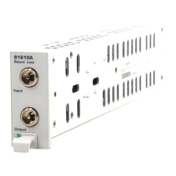
Page 16: The Return Loss Module
Figure 2 The Keysight 81610A Return Loss module The Keysight 81610A series Return Loss module does not include an internal laser source. It is used in conjunction with an appropriate external source to perform return loss measurements on both WDM components and broadband devices. - Page 17 Output 9/125 μm Figure 3 The Contents of the Keysight 81613A Return Loss modules All Keysight 8161x series Return Loss modules include a monitor diode to compensate for power variation in the light source. Keysight 81610A/11A/12A/13A/14A Return Loss Module, Edition 6...
-
Page 18: A Description Of The Front Panel
• In order to obtain reliable return loss values connectors must be in good condition. Damage to connectors is not included in the warranty for the Keysight 8161x series Return Loss modules Keysight 81610A/11A/12A/13A/14A Return Loss Module, Edition 6... -
Page 19: What Is Return Loss
Return Loss dB – --------------------------------------------- dB Incident Power Return loss can be measured in several ways. A typical setup using the Keysight 81610A Return Loss module, where the DUT is a connector pair, is described in Figure External Laser Source... -
Page 20: What Is Insertion Loss
--------------------------------------------------- - Incident Power Insertion Loss can be measured in several ways. A typical setup using the Keysight 81610A Return Loss module, where the DUT is a connector pair, is described in Figure 7 81610A External Laser Power Meter... -
Page 21: How To Choose A Light Source
If you use high-coherence light sources, you can improve performance by: • modulating the output signal at 2 kHz or higher, or • using the coherence control to reduce the coherence length of the signal. Keysight 81610A/11A/12A/13A/14A Return Loss Module, Edition 6... -
Page 22: Calibration Measurements
Making a Return Loss Measurement Connectors Fiber patchcords for measurement or calibration must have an angled, APC, connector at the return loss module output port. Keysight 81610A/11A/12A/13A/14A Return Loss Module, Edition 6... -
Page 23: Setup
2 Make sure that the source is not active and that you have covered the end of the patchcord to prevent light being coupled into the end. Move to the Return Loss module channel and press [Zero] to remove electrical offsets in the instrument. Keysight 81610A/11A/12A/13A/14A Return Loss Module, Edition 6... - Page 24 Figure 10 Keysight 8161x Details Screen Set Wavelength 4 Move to [λ], then set this parameter to Extern. 5 Enable the source. Keysight 81610A/11A/12A/13A/14A Return Loss Module, Edition 6...
-
Page 25: Calibrating The Return Loss Module
“Calculating the Front Panel Delta” on page 43), you must also measure the insertion loss of the Reference Cable and measurement patchcord. These procedures are decribed in “Calibration using the Keysight 81610CC Reference Cable” on page Keysight 81610A/11A/12A/13A/14A Return Loss Module, Edition 6... -
Page 26: Calibration Using The Keysight 81000Br Reference Reflector
4 Move to [FPDelta], press [Edit], set the value to 0.000, then press [OK]. 5 Move to [RLref>] and make sure that the displayed value is correct. Set [RLref] to the value of the return loss of the reference reflection you are Keysight 81610A/11A/12A/13A/14A Return Loss Module, Edition 6... - Page 27 The [RL] value changes to the same value as entered for [RLref]. An alternative step 6 is to select the Return Loss module’s [Detail] screen, then press [RefCal] Keysight 81610A/11A/12A/13A/14A Return Loss Module, Edition 6...
-
Page 28: Termination Calibration
[Para] values used by the Return Loss monitor’s power sensor and monitor diode. T IP An alternative steps 3 and 4 is to select the Return Loss module’s [Details] screen, then press [TermCal]. Keysight 81610A/11A/12A/13A/14A Return Loss Module, Edition 6... -
Page 29: Calibration Using The Keysight 81610Cc Reference Cable
3 Move to [RLref], press [Edit]. Make sure that the displayed value of <RLref> is correct. If it is not, move to [RLref], press [Edit], set the value the return loss value of the reference cable you are using, then press [OK]. Keysight 81610A/11A/12A/13A/14A Return Loss Module, Edition 6... -
Page 30: Front Panel Delta Calibration
Power 8163A Lightwave Multimeter 8161x Sensor Reference Cable Agilent 81610CC Figure 19 Measuring the Power Transmitted through the Reference Cable - Internal Source 2 Move to the Power Sensor channel: – Press [Menu]. Keysight 81610A/11A/12A/13A/14A Return Loss Module, Edition 6... - Page 31 – The Power Sensor channel displays a power value in dB that is equal to the front panel delta of the measurement system. – Press [Close] to exit from the menu. 3 Move to the Return Loss module channel: Keysight 81610A/11A/12A/13A/14A Return Loss Module, Edition 6...
-
Page 32: Termination Calibration Using The Measurement Patchcord
T IP You can do this by wrapping the fiber five times around the shaft of a screwdriver (or some similar object with a diameter of between 5mm and 7mm). Keysight 81610A/11A/12A/13A/14A Return Loss Module, Edition 6... - Page 33 3 Move to <Terminated calibration> and press Enter. The instrument measures the power reflected by the component, and sets the [Para] values used by the Return Loss monitor’s power sensor and monitor diode. Keysight 81610A/11A/12A/13A/14A Return Loss Module, Edition 6...
-
Page 34: How To Measure Return Loss
30, set the [Ref] parameter to the power transmitted through the Reference Cable. The displayed power in dB is equal to the insertion loss. Set the Front Panel Delta as described on “Front Panel Delta Calibration” on page Keysight 81610A/11A/12A/13A/14A Return Loss Module, Edition 6... -
Page 35: Viewing The Calibration Values
The Calibration Parameters Screens - Return Loss Diode 2 Press [Next]. The Calibration parameters screen for the Monitor Diode appears, as displayed in Figure 27. This screen shows current value for the following quantities: Keysight 81610A/11A/12A/13A/14A Return Loss Module, Edition 6... - Page 36 Figure 28. This screen shows current value for the following quantities: – [FPDelta], the loss correction, in dB, due to differences in loss between the reference cable and the measurement patchcord. Keysight 81610A/11A/12A/13A/14A Return Loss Module, Edition 6...
- Page 37 – [RLref], the value of the return loss of the reference relector used. If you are using a reference cable, this value will be around 14.6 dB Figure 28 The Calibration Parameters Screens - User Data Keysight 81610A/11A/12A/13A/14A Return Loss Module, Edition 6...
-
Page 38: A Background To Return Loss Measurement
Note you can only measure the Front Panel Delta if you use a Reflection Reference Cable. The reflection factor for the component is called R . Normally the return loss for the component (RL ) is specified, but these values are related: – – ------- Keysight 81610A/11A/12A/13A/14A Return Loss Module, Edition 6... -
Page 39: Measuring The Power Transmitted Through The Reflection Reference
This is our termination parameter. 81610A Reflection-free Termination measurement patchcord Reflectivity Figure 31 Measuring the Power with the Connector Terminated This measured power for the termination parameter is called P Keysight 81610A/11A/12A/13A/14A Return Loss Module, Edition 6... -
Page 40: Measuring The Power Transmitted Through The Measurement Patchcord
DUT. The DUT should be terminated. 81610A Reflection-free Termination measurement patchcord Figure 33 Measuring the Reflections from the Device Under Test The instrument measures the power reflected from the DUT. This power is called P Keysight 81610A/11A/12A/13A/14A Return Loss Module, Edition 6... -
Page 41: Measuring The Power Transmitted Through The Dut
• the part of the power, reflected by the component, which is transmitted through the coupler, and • the reflections due to the measurement system. Keysight 81610A/11A/12A/13A/14A Return Loss Module, Edition 6... - Page 42 This gives the following equation: para para For “Measuring the Reflections from the DUT” on page 40, the value of the reflection factor of the DUT is called R . This gives the following equation: Keysight 81610A/11A/12A/13A/14A Return Loss Module, Edition 6...
-
Page 43: Calculating The Front Panel Delta
“How to Measure Return Loss” on page 34. This is caused by differences in reflections from the front panel connector and also differences in the backscatter level of the fibers. Keysight 81610A/11A/12A/13A/14A Return Loss Module, Edition 6... - Page 44 -------------- - ------------- - Meas Meas The loss variation, ΔL, due to exchanging the reference cable for the measurement cable is given by: (16) ΔL – ------------- - – -------------- - Meas Meas Keysight 81610A/11A/12A/13A/14A Return Loss Module, Edition 6...
-
Page 45: Calculating The Insertion Loss Of The Dut
Measurement Patchcord” on page 40 and the power transmitted through the DUT, see “Measuring the Power Transmitted Through the DUT” on page 41. The equation below gives the insertion loss of the DUT, IL (18) – -------------- - Meas Keysight 81610A/11A/12A/13A/14A Return Loss Module, Edition 6... - Page 46 Getting Started with Return Loss A Background to Return Loss Measurement Keysight 81610A/11A/12A/13A/14A Return Loss Module, Edition 6...
-
Page 47: Accessories
Accessories Keysight 8161x series Return Loss modules are available in various configurations for the best possible match to the most common applications. This chapter provides information on the available options and accessories. -
Page 48: Modules And Options
Accessories Modules and Options Modules and Options Keysight 8163A Mainframe Ch.A Ch.B R eturn Loss Module 81610A R eturn Loss Module without internal source Angled Input 81611A R eturn Loss Module (1310nm ) Keysight Keysight Keysight Keysight Keysight contact 81612A "... -
Page 49: Specifications
Specifications Keysight 81610A/11A/12A/13A/14A Return Loss Modules are produced to the ISO 9001 international quality system standard as part of Keysight Technologies’s commitment to continually increasing customer satisfaction through improved quality control. Specifications describe the modules’ warranted performance. Supplementary performance characteristics describe the modules’ non-warranted typical performance. -
Page 50: Definition Of Terms
(no physical connection!). Temperature and wavelength ranges as specified. The return loss of the reference cable is defined by the transition from the reference surface to air. Keysight 81610A/11A/12A/13A/14A Return Loss Module, Edition 6... -
Page 51: Dynamic Range
R is an arbitary return loss reference, and apostrophe ( ‘ ) indicates measured quantities. The relative uncertainty includes receiver nonlinearity, receiver polarization sensitivity, and uncertainty of input power monitoring. Keysight 81610A/11A/12A/13A/14A Return Loss Module, Edition 6... - Page 52 Conditions: “Termination calibration” prior to measurement. Constant ambient temperature, constant wavelength and source polarization state. Other conditions as specified. This parameter is needed to determine the accuracy of return loss changes, for example caused by adjusting an optical component. Keysight 81610A/11A/12A/13A/14A Return Loss Module, Edition 6...
-
Page 53: Total Uncertainty
(no reflectance calibration) and a front panel delta of zero (no front panel calibration are used. Conditions: Measurement patchcord connectors in perfect optical condition. Length of measurement patchcord and connector return loss as specified. Other conditions as specified. Keysight 81610A/11A/12A/13A/14A Return Loss Module, Edition 6... -
Page 54: Return Loss Module Specifications
FP Sources: 81650A, 81651A, 81652A, 81654A with active coherence control Reference Cable 81610CC used for total uncertainty Length of measurement patchcord ≤ 2m, angled connector in optimal optical conditions Warm-up time 60 minutes if not previously stored at the same temperature. Keysight 81610A/11A/12A/13A/14A Return Loss Module, Edition 6... - Page 55 1310 and 1550 nm ± 20 nm Clean reference reflector in perfect optical condition (Do not use with contact-type connectors). To connect to Return Loss Modules the cable requires conector interface 81000SI DIN47256. Keysight 81610A/11A/12A/13A/14A Return Loss Module, Edition 6...
-
Page 56: Return Loss Module Specifications With Internal Source
Return Loss Module Specifications with Internal Source Return Loss Module Specifications with Internal Source For use with external sources the specifications of the Keysight 81610A Return Loss Module apply. All modules require angled contact (8°) at input and output connectors Keysight 81610A/11A/12A/13A/14A Return Loss Module,... - Page 57 Factory defaults are set to (no user calibration necessary): length of measurement patchcord ≤ 2 m, return loss of connectors ≥70 dB For measurements performed immediately after calibration Warm-up time 60 minutes if not previously stored at the same temperature. Keysight 81610A/11A/12A/13A/14A Return Loss Module, Edition 6...
- Page 58 Specifications Return Loss Module Specifications with Internal Source Keysight 81610A/11A/12A/13A/14A Return Loss Module, Edition 6...
-
Page 59: Performance Tests
Performance Tests The procedures in this section test the performance of the instrument. The complete specifications to which the Keysight 81610A Return Loss module, and the Keysight 81610CC Reference Cable, are tested are given in “Specifications” on page 49. The Return Loss of Keysight 81610CC Reference Cable is printed on the cable. -
Page 60: Equipment Required
– 81113SC (1 ea) – – Connector Interfaces 81000FI x (2 ea) x (4 ea) 81000SI x (4 ea) x (2 ea) Connector Feedthrough 1005-0256 – – Plastic Cap 5040-9351 (2 ea) – Keysight 81610A/11A/12A/13A/14A Return Loss Module, Edition 6... -
Page 61: Test Record
Keysight Technologies. Test Failure If the Keysight 81610A/13A Return Loss module fails any performance test, return the instrument to the nearest Keysight Technologies Sales/Service Office for repair. The 81610CC Reference Cable may be recalibrated using the procedure given in “Calibrating the 81610CC Reference Cable”... -
Page 62: Performance Test Instructions
Performance Test Instructions Do not connect a Keysight 81000BR Reference Reflector directly to the Keysight 81610A/13A Return Loss module. Make sure that all optical connections of the test setups given in the procedure are dry and clean. DO NOT USE INDEX MATCHING OIL. For cleaning, use the cleaning instructions given in “Cleaning Information”... - Page 63 Note this value in the Test Record as RLref d Press [RefCal] to calibrate the Return Loss module at reference condition. 8 At the Power meter, press [Disp → Ref]. The Power meter should now read 0.0 dB. Keysight 81610A/11A/12A/13A/14A Return Loss Module, Edition 6...
-
Page 64: 8156A #201
Cable, since a physical connection is made. When the straight end of the 81610CC Reference Cable is connected to the 81634A Power Sensor module, no physical connection is made, so there should be no degradation of connector quality. Keysight 81610A/11A/12A/13A/14A Return Loss Module, Edition 6... - Page 65 17 For each Return Loss reading, calculate the result by: a Calcuating the Effective Attenuation by multiplying the Actual Attenuation by 2. b Subtracting the RLref value from the Return Loss value, then subtracting the Effective Attenuation value. An example follows: Keysight 81610A/11A/12A/13A/14A Return Loss Module, Edition 6...
-
Page 66: Example For Keysight 81610A Return Loss Module
Performance Tests Performance Test Instructions Example for Keysight 81610A Return Loss module Subtract Actual Return Loss Actual Attenuation Result [dB] Reading [dB] [dB] Effective Attenuation [dB] RLref [dB] EA=2AA RLref = RL - EA - RLref 14.8 0.00 +0.0 20.0 2.55... -
Page 67: Keysight 81610A/13A: Relative Uncertainty Of Return Loss And Dynamic Range
4 Zero the return loss meter as well as the power meter. 5 Enable the internal laser source of the return loss module and allow 20min for it to stabilize. Keysight 81610A/11A/12A/13A/14A Return Loss Module, Edition 6... - Page 68 Loss meter. Make sure you enter the sign of this value correctly. 11 At the optical attenuator: a Set 'Attenuation' to 60.0dB. b Set 'Wavelength' to the wavelength of the RTL source. Enable the attenuator. Keysight 81610A/11A/12A/13A/14A Return Loss Module, Edition 6...
- Page 69 Press the 'autoscan' button to start scrambling the polarization. 21 At the return loss module: a Set the averaging time [Averaging time] to 50ms. b Set [Data Points] to 1000. Select [MinMax mode], select the [continuous] mode. Keysight 81610A/11A/12A/13A/14A Return Loss Module, Edition 6...
- Page 70 To calculate the relative uncertainty of return loss, subtract the RLref and the TA value from the RL value. d Calculate the revised specification by subtracting the PDL uncertainty from the specifications. Keysight 81610A/11A/12A/13A/14A Return Loss Module, Edition 6...
- Page 71 <± 0.8 62.5 -1.20 -2.40 -47.40 +0.29 <± 0.68 <± 0.8 65.0 -1.20 -2.40 -49.80 +0.39 <± 1.78 <± 1.9 67.5 -1.25 -2.40 -52.30 +0.39 <± 1.78 <± 1.9 70.0 -1.00 -2.00 -54.30 +0.89 Keysight 81610A/11A/12A/13A/14A Return Loss Module, Edition 6...
-
Page 72: Calibrating The 81610Cc Reference Cable
Set the wavelength [ λ] to 1310 nm Press [ Mod Src ] and select < Coherence Ctrl > to modulate the source using coherence control. Allow the Laser Source to stabilize for at least 20 minutes. Keysight 81610A/11A/12A/13A/14A Return Loss Module, Edition 6... - Page 73 Laser Source 8163A 81654A 11896A Mainframe 8163A w/ 8161xA RTL and 81634A Power Sensor Optical Attenuator 8156A 8163A 8161xA 81634A 8156A #101 81610CC Figure 43 81610CC Reference Cable - Setting the Calibration Reference Keysight 81610A/11A/12A/13A/14A Return Loss Module, Edition 6...
- Page 74 If the return loss of the 81610CC Reference Cable differs from the value printed on the cable, use the newly measured return loss value as the Reference Reflectance for the wavelength at which it was measured . Keysight 81610A/11A/12A/13A/14A Return Loss Module, Edition 6...
- Page 75 ___________ Hz Firmware Rev. Line Frequency _________________________ Test Facility Customer _________________________ _________________________ Performed by Report No _________________________ ______________________________________________________________________ Special Notes ______________________________________________________________________ ______________________________________________________________________ ______________________________________________________________________ ______________________________________________________________________ ______________________________________________________________________ ______________________________________________________________________ ______________________________________________________________________ ______________________________________________________________________ ______________________________________________________________________ ______________________________________________________________________ ______________________________________________________________________ ______________________________________________________________________ ______________________________________________________________________ ______________________________________________________________________ Keysight 81610A/11A/12A/13A/14A Return Loss Module, Edition 6...
- Page 76 Performance Tests Performance Test Instructions Keysight 81610A/11A/12A/13A/14A Return Loss Module, Edition 6...
-
Page 77: 81610Cc (1 Ea)
____________ ___________ ____________________________ ____________ ____________ ___________ ____________________________ ____________ ____________ ___________ ____________________________ ____________ ____________ ___________ ____________________________ ____________ ____________ ___________ Accessories Product Product Product Calibration Cable 81610CC Singemode Fibers 81113PC 81113SC Connector Interfaces 81000FI 81000SI Keysight 81610A/11A/12A/13A/14A Return Loss Module, Edition 6... - Page 78 Performance Tests Performance Test Instructions Performance Test for the Keysight 81610A Page 3 of 3 Model: Keysight 81610A Return Loss module Report No ________ Date ________________ Test Test Description Min. Result Max. Measurement Number Spec. Spec. Uncertainty [dB] Relative Uncertainty of RL [dB]...
- Page 79 ___________ Hz Firmware Rev. Line Frequency _________________________ Test Facility Customer _________________________ _________________________ Performed by Report No _________________________ ______________________________________________________________________ Special Notes ______________________________________________________________________ ______________________________________________________________________ ______________________________________________________________________ ______________________________________________________________________ ______________________________________________________________________ ______________________________________________________________________ ______________________________________________________________________ ______________________________________________________________________ ______________________________________________________________________ ______________________________________________________________________ ______________________________________________________________________ ______________________________________________________________________ ______________________________________________________________________ ______________________________________________________________________ Keysight 81610A/11A/12A/13A/14A Return Loss Module, Edition 6...
- Page 80 Performance Tests Performance Test Instructions Keysight 81610A/11A/12A/13A/14A Return Loss Module, Edition 6...
- Page 81 ____________ ____________ ___________ ____________________________ ____________ ____________ ___________ ____________________________ ____________ ____________ ___________ ____________________________ ____________ ____________ ___________ ____________________________ ____________ ____________ ___________ Accessories Product Product Product Calibration Cable 81610CC Fiber Feedthroough 1005-0256 Connector Interfaces 81000SI 81000FI Keysight 81610A/11A/12A/13A/14A Return Loss Module, Edition 6...
- Page 82 RLref 15.0 <+0.5 20.0 <+0.5 25.0 <+0.5 30.0 <+0.5 35.0 <+0.5 40.0 <+0.5 45.0 <+0.5 50.0 <+0.5 52.5 <+0.5 55.0 <+0.5 57.5 <+0.6 60.0 <+0.6 62.5 <+0.8 65.0 <+0.8 67.5 <+1.9 70.0 <+1.9 Keysight 81610A/11A/12A/13A/14A Return Loss Module, Edition 6...
- Page 83 Ambient Temperature ___________ % Relative Humidity _________________________ Test Facility Customer _________________________ _________________________ Performed by Report No _________________________ ______________________________________________________________________ Special Notes ______________________________________________________________________ ______________________________________________________________________ ______________________________________________________________________ ______________________________________________________________________ ______________________________________________________________________ ______________________________________________________________________ ______________________________________________________________________ ______________________________________________________________________ ______________________________________________________________________ ______________________________________________________________________ ______________________________________________________________________ ______________________________________________________________________ ______________________________________________________________________ ______________________________________________________________________ Keysight 81610A/11A/12A/13A/14A Return Loss Module, Edition 6...
-
Page 84: 81113Pc (1 Ea)
____________ ___________ ____________________________ ____________ ____________ ___________ ____________________________ ____________ ____________ ___________ ____________________________ ____________ ____________ ___________ ____________________________ ____________ ____________ ___________ ____________________________ ____________ ____________ ___________ Accessories Product Product Product Singemode Fibers 81113PC Connector Interfaces 81000FI 81000SI Keysight 81610A/11A/12A/13A/14A Return Loss Module, Edition 6... - Page 85 Date ________________ Test Test Description Min. Result Max. Measurement Number Spec. Spec. Uncertainty [dB] Reference Reflectance Wave- = Ref - length Meas Meas 1310 nm ± 0.20 dB 1550 nm ± 0.20 dB Keysight 81610A/11A/12A/13A/14A Return Loss Module, Edition 6...
- Page 86 Performance Tests Performance Test Instructions Keysight 81610A/11A/12A/13A/14A Return Loss Module, Edition 6...
-
Page 87: Cleaning Information
If you are unsure of the correct cleaning procedure for your optical device, we recommend that you first try cleaning a dummy or test device. Keysight Technologies assume no liability for the customer’s failure to comply with these requirements. Cleaning Instructions for this Instrument This Cleaning Information applies to a number of different types of Optical Equipment. -
Page 88: Safety Precautions
Furthermore, the power density may burn dust into the fiber and cause additional damage (for example, 0 dBm optical power in a single mode fiber causes a power density of approximately 16 million W/m ). If this happens, measurements become inaccurate and non-repeatable. Keysight 81610A/11A/12A/13A/14A Return Loss Module, Edition 6... -
Page 89: What Do I Need For Proper Cleaning
Compressed air Dust and shutter caps All of Keysight Technologies’ lightwave instruments are delivered with either laser shutter caps or dust caps on the lightwave adapter. Any cables come with covers to protect the cable ends from damage or contamination. -
Page 90: Isopropyl Alcohol
We recommend that you do not use normal cotton tissues, but multi-layered soft tissues made from non-recycled cellulose. Cellulose tissues are very absorbent and softer. Consequently, they will not scratch the surface of your device over time. Keysight 81610A/11A/12A/13A/14A Return Loss Module, Edition 6... -
Page 91: Pipe Cleaner
First spray into the air, as the initial stream of compressed air could contain some condensation or propellant. Such condensation leaves behind a filmy deposit. Please be friendly to your environment and use a CFC-free aerosol. Keysight 81610A/11A/12A/13A/14A Return Loss Module, Edition 6... -
Page 92: Additional Cleaning Equipment
Only use water if you are sure that there is no other way of cleaning your optical device without causing corrosion or damage. Do not use hot water, as this may cause mechanical stress, which can damage your optical device. Keysight 81610A/11A/12A/13A/14A Return Loss Module, Edition 6... -
Page 93: Premoistened Cleaning Wipes
Listed below are some hints on how best to keep your connectors in the best possible condition. Making Connections Before you make any connection you must ensure that all cables and connectors are clean. If they are dirty, use the appropriate cleaning procedure. Keysight 81610A/11A/12A/13A/14A Return Loss Module, Edition 6... -
Page 94: Cleaning Instrument Housings
Always keep the caps on the equipment when it is not in use. All of Keysight Technologies’ lightwave instruments and accessories are shipped with either laser shutter caps or dust caps. If you need additional or replacement dust caps, contact your nearest Keysight Technologies Sales/Service Office. -
Page 95: How To Clean Connectors
2 Blow away any remaining lint with compressed air. Procedure for Stubborn Dirt Use this procedure when there is greasy dirt on the connector: 1 Moisten a new cotton swab with isopropyl alcohol. Keysight 81610A/11A/12A/13A/14A Return Loss Module, Edition 6... -
Page 96: How To Clean Connector Adapters
2 Clean the adapter by rubbing the cotton swab over the surface using a small circular movement. 3 Take a new, dry soft tissue and remove the alcohol, dissolved sediment and dust, by rubbing gently over the surface using a small circular movement. Keysight 81610A/11A/12A/13A/14A Return Loss Module, Edition 6... -
Page 97: How To Clean Connector Interfaces
4 Clean the interface by rubbing the cotton swab over the surface using a small circular movement. 5 Using a new, dry pipe cleaner, and a new, dry cotton swab remove the alcohol, any dissolved sediment and dust. 6 Blow away any remaining lint with compressed air. Keysight 81610A/11A/12A/13A/14A Return Loss Module, Edition 6... -
Page 98: How To Clean Bare Fiber Adapters
2 Clean the adapter by rubbing a new, dry cotton swab over the surface using a small circular movement. 3 Blow away any remaining lint with compressed air. Keysight 81610A/11A/12A/13A/14A Return Loss Module, Edition 6... -
Page 99: How To Clean Lenses
If there are fluids or fat in the connector, please refer the instrument to the skilled personnel of Keysight’s service team. Keysight 81610A/11A/12A/13A/14A Return Loss Module, Edition 6... - Page 100 Never try to open the instrument and clean the optical block by yourself, because it is easy to scratch optical components, and cause them to become misaligned. Keysight 81610A/11A/12A/13A/14A Return Loss Module, Edition 6...
-
Page 101: How To Clean Instruments With An Optical Glass Plate
How to clean instruments with an optical glass plate Some instruments, for example, the optical heads from Keysight Technologies have an optical glass plate to protect the sensor. Clean this glass plate in the same way as optical lenses (see “How to clean lenses” on page 99 ). -
Page 102: How To Clean Instruments With A Recessed Lens Interface
Keep your dust and shutter caps on when your instrument is not in use. This should prevent it from getting too dirty. If you must clean such instruments, please refer the instrument to the skilled personnel of Keysight’s service team. Keysight 81610A/11A/12A/13A/14A Return Loss Module, Edition 6... -
Page 103: How To Clean Optical Devices Which Are Sensitive To Mechanical Stress And Pressure
1 Put the film on the surface and wait at least 30 minutes to make sure that the film has had enough time to dry. Keysight 81610A/11A/12A/13A/14A Return Loss Module, Edition 6... -
Page 104: How To Clean Metal Filters Or Attenuator Gratings
1 Put the optical device into a bath of isopropyl alcohol, and wait at least 10 minutes. 2 Remove the fluid using compressed air at some distance and with low pressure. If there are any streaks or drying stains on the surface, repeat the whole cleaning procedure. Keysight 81610A/11A/12A/13A/14A Return Loss Module, Edition 6... -
Page 105: Additional Cleaning Information
Preferred Procedure Use the following procedure on most occasions. 1 Blow away any dust or dirt with compressed air. Procedure for Stubborn Dirt Use this procedure when there is greasy dirt on the lens: Keysight 81610A/11A/12A/13A/14A Return Loss Module, Edition 6... - Page 106 2 Take a new, dry soft tissue and remove the alcohol, dissolved sediment and dust, by rubbing gently over the surface using a small circular movement. 3 Blow away remaining lint with compressed air. Keysight 81610A/11A/12A/13A/14A Return Loss Module, Edition 6...
-
Page 107: Other Cleaning Hints
This Appendix highlights the main cleaning methods, but cannot address every individual circumstance. This section contain some additional hints which we hope will help you further. For further information, please contact your local Keysight Technologies representative. Making the connection Before you make any connection you must ensure that all lightwave cables and connectors are clean. - Page 108 Cleaning Information Other Cleaning Hints Keysight 81610A/11A/12A/13A/14A Return Loss Module, Edition 6...
- Page 109 Optical Output 18 Performance Tests 59 81610A 75, 79, 83 Dynamic Range 62 Relative Uncertainty 62 Required Equipment 60 Test Failure 61 Recommended Connector Interfaces 48 Return Loss 15 Getting Started 16 Light Source 21 Keysight 81610A/11A/12A/13A/14A Return Loss Module, Edition 6...
- Page 110 This information is subject to change without notice. © Keysight Technologies 2000, 2015 Edition 6, February 2015 www.keysight.com...
Need help?
Do you have a question about the 81610A and is the answer not in the manual?
Questions and answers