Table of Contents
Advertisement
Quick Links
Advertisement
Table of Contents

Subscribe to Our Youtube Channel
Related Manuals for Keysight Technologies 81650A


Summary of Contents for Keysight Technologies 81650A
- Page 1 Keysight 81650A/1A/4A/5A/ 6A/7A Laser Source Modules User’s Guide...
- Page 2 FURNISHING, USE, OR PERFORMANCE OF agreement and written consent from related to commercial computer software THIS DOCUMENT OR ANY INFORMATION Keysight Technologies as governed by or commercial computer software docu- CONTAINED HEREIN. SHOULD KEYSIGHT United States and international copyright mentation that is not customarily provided AND THE USER HAVE A SEPARATE laws.
-
Page 3: Table Of Contents
Laser Class 1M Laser Class 1 What is a Laser Source Module ? A Description of the Front Panel Optical Output Keysight Technologies Sales and Service Offices 2 Accessories Modules and Options 3 Specifications Definition of Terms Laser Source Module Specifications... - Page 4 Contents 4 Performance Tests Equipment Required Test Record Test Failure Instrument Specification Performance Test Center Wavelength and Spectral Bandwidth Test Output Power and Stability Test 5 Cleaning Instructions Cleaning Instructions for this Instrument Safety Precautions Why is it important to clean optical devices? What do I need for proper cleaning? Standard Cleaning Equipment Additional Cleaning Equipment...
- Page 5 Contents How to clean bare fiber adapters Preferred Procedure Procedure for Stubborn Dirt How to clean lenses Preferred Procedure Procedure for Stubborn Dirt How to clean instruments with a fixed connector interface How to clean instruments with an optical glass plate How to clean instruments with a physical contact interface Preferred Procedure Procedure for Stubborn Dirt...
- Page 7 Initial Safety Information for Laser Source Modules / 11 Laser Safety Labels / 13 What is a Laser Source Module ? / 14 Keysight Technologies Sales and Service Offices / 16 This chapter introduces the features of the Keysight 8165xA Fabry- Perot laser source modules.
-
Page 8: Safety Considerations
Keysight Technologies assumes no liability for the customer’s failure to comply with these requirements. Before operation, review the instrument and manual, including the safety page, for safety markings and instructions. -
Page 9: Line Power Requirements
Lightwave Measurement System, and 8166A/B Light wave Multichannel System User’s Guide summarizes the operating ranges for the 81650A/1A/2A/4A/5A/6A/7A Laser Source Modules. In order for these modules to meet specifications, the operating environment must be within the limits specified for the 8163A/B, 8164A/B, and 8166A/B. -
Page 10: Environmental Information
Getting Started with Laser Source Environmental Information This product complies with the WEEE Directive (2002/96/EC) marking requirements. The affixed label indicates that you must not discard this electrical/ electronic product in domestic household waste. Product Category: With reference to the equipment types in the WEEE Directive Annex I, this product is classed as a “Monitoring and Control instrumentation”... -
Page 11: Initial Safety Information For Laser Source Modules
IEC 60825- 1 (2007). The laser sources comply with 21 CFR 1040.10 except for deviations pursuant to Laser Notice No. 50, dated 2007- June- Table 1 Standard Laser Source Modules Laser Safety Information Keysight 81650A Keysight 81651A Keysight 81654A Laser type... - Page 12 Getting Started with Laser Source Keysight 81655A Keysight 81656A Keysight 81657A Laser Class according to IEC 60825-1 (2007) Max. permissible CW output power 52 mW 163 mW 52 mW/163 mW * Max. CW output power is defined as the highest possible optical power that the laser source can produce at its output connector. Keysight Laser Source Modules User’s Guide...
-
Page 13: Laser Safety Labels
Laser Class 1 Figure 2 Laser Class 1 Safety Label - Keysight 81650A/1A/4A” Keysight Laser Source Modules User’s Guide... -
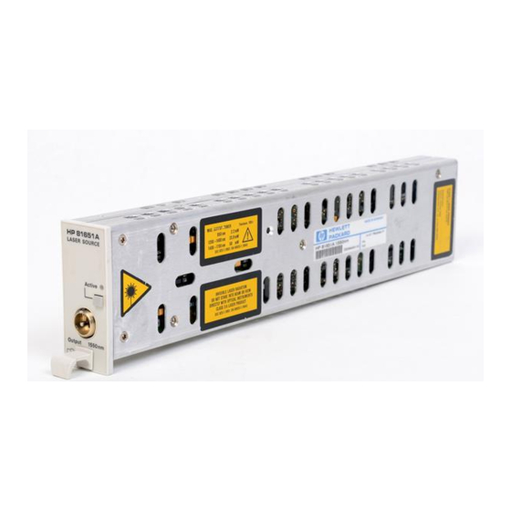
Page 14: What Is A Laser Source Module
A laser source module is a laser source that emits radiation at a specific optical wavelength. The specific range of fixed wavelength for each of the Keysight Technologies laser source modules can be found in the Specifications chapter of the relevant module’s User’s Guide. -
Page 15: Optical Output
Getting Started with Laser Source Optical Output Angled Contact Connectors The Keysight Fabry- Perot laser sources are equipped with a straight contact optical output connector as standard. Figure 4 Straight Contact Connector Symbols Figure 4 shows the symbol for straight contact connectors. Keysight Laser Source Modules User’s Guide... -
Page 16: Keysight Technologies Sales And Service Offices
Getting Started with Laser Source Keysight Technologies Sales and Service Offices For more information about Keysight Technologies test and measurement products, applications, services, and for a current sales office listing, visit our web site: http://www.keysight.com/find/lightwave You can also contact one of the following centers and ask for a test and measurement sales representative. - Page 17 Modules User’s Guide Accessories Modules and Options / 18 The Keysight 81650A/1A/2A/4A/5A/6A/7A Laser Source Modules are available in various configurations for the best possible match to the most common applications. This chapter provides information on the available options and accessories.
-
Page 18: Modules And Options
Accessories Modules and Options Figure 5 Recommended Connector Interfaces Keysight Laser Source Modules User’s Guide... - Page 19 / 23 The Keysight 81650A/1A/2A/4A/5A/6A/7A Laser Source Modules are produced to the ISO 9001 international quality system standard as part of Keysight Technologies’ commitment to continually increasing customer satisfaction through improved quality control. Specifications describe the modules’ and heads’ warranted performance.
-
Page 20: Definition Of Terms
Specifications Definition of Terms This section defines terms that are used both in this chapter and Performance Tests on page Generally, all specifications apply for the given environmental conditions and after warm-up time. Measurement principles are indicated. Alternative, measurement principles of equal value are also acceptable. Center wavelength The center wavelength is defined as the spectral center of gravity. - Page 21 Specifications λ where: = center wavelength of laser diode in vacuum center Σ λ = total power, in watts total = power of i th longitudinal mode λ = wavelength of i th longitudinal mode, in vacuum M = multiplication factor; for a source with a Gaussian envelope M = 2.35;...
- Page 22 Specifications Conditions Uninterrupted line voltage, constant power level setting, CW operation, operating temperature change within specified limits, minimum return loss as specified, all polarization states of back-reflection included. Measurement The change of the output power is monitored while the source’s susceptibility to back-reflection is tested by disturbing the laser oscillation with power reflected back into the laser, P .
-
Page 23: Laser Source Module Specifications
Specifications apply to the end of a 2-meter long fiber cable (as specified under fiber type). All specifications are valid for an attenuation setting of 0.0 dB. All modules require straight output connectors. Table 3 Standard Laser Source Module Specifications 81650A 81651A 81654A Laser Type Fabry-Perot Laser Diode Center Wavelength... -
Page 24: Laser Source Module Specifications (High Power, 13 Dbm)
Specifications Supplementary Performance Characteristics Internal d igital modulation mode: 270 Hz, 330 Hz, 1 kHz, 2 kHz, and free selection 200 Hz to 10 kHz. All outputs are pulse shaped, duty cycle 50%. Improved coherence control for line-width broadening. Output attenuation: The output power of all source modules can be attenuated from 0 dB to 6 dB in steps of 0.1 dB. - Page 25 Specifications 1 Central wavelength is shown on display 2 rms: root mean square 3 Warm-up time 20 minutes, if previously stored at the same temperature ± 4 Constant temperature ΔT = 1°C Supplementary Performance Characteristics Internal d igital modulation mode: 270 Hz, 330 Hz, 1 kHz, 2 kHz, and free selection 200 Hz to 10 kHz.
-
Page 27: Performance Tests
The procedures in this section test the optical performance of the instrument. The complete specifications to which the Keysight 81650A/1A/4A/5A/6A/7A Laser Source module is tested are given in Performance Tests on page 25. All tests can be performed without access... -
Page 28: Equipment Required
Performance Tests Equipment Required Equipment required for the performance test is listed below. Table 5 Required Equipment Instrument/Accessory Recommended Model 81650A – Required Al ternative Models 81657A Characteristics Multimeter Mainframe 8163A Keysight 8163B, 8164B Power Meter Standard 81533B Optical Head Interface... -
Page 29: Test Record
(if you are already familiar with the test procedures). The Test Record can also be used as a permanent record and may be reproduced without written permission from Keysight Technologies. Keysight Laser Source Modules User’s Guide... -
Page 30: Test Failure
Performance Tests Test Failure If the Keysight 81650A/1A/4A/5A/6A/7A Laser Source module fails any performance test, return the instrument to the nearest Keysight Technologies Sales/Service Office for repair. Keysight Laser Source Modules User’s Guide... -
Page 31: Instrument Specification
Specifications are the performance characteristics of the instrument that is certified. These specifications, listed in Specifications on page 19, are the performance standards or limits against which the Keysight Technologies 81650A/1A/4A/5A/6A/7A Laser Source module can be tested. Specifications on page 19 also lists some supplemental characteristics of the Keysight Technologies 81650A/1A/4A/5A/6A/7A Laser Source module and should be considered as additional information. -
Page 32: Performance Test
Performance Tests Performance Test The performance tests given in this section includes the Output Power Test and the Stability Test. Perform each step in the order given, using the corresponding test equipment. Make sure that all optical connections of the test setups given in the NOTE procedure are dry and clean. - Page 33 In the field given at the top of the screen, the Fabry-Perot laser test results are shown. Note the mean wavelength and the rms bandwidth (sigma) in the test record. Example for Keysight Technologies 81650A Parameter Min Spec Resul t...
-
Page 34: Output Power And Stability Test
Performance Tests Output Power and Stability Test Figure 7 Measurement Setup for Output Power and Stability Test Output Power Test Make absolutely sure that cable connectors and detector windows are clean. Enable the laser output of the Keysight 8165xA and allow instruments to warm up for at least 20 minutes. - Page 35 Performance Tests Stability Test Make sure the laser source Keysight 8165xA has warmed up for 20 minutes. Select the channel with the source. a Ensure that the modulation of the source is switched off. b Make sure that the attenuation of the source is set to zero. Using the Keysight 81113PC cable, connect the output of the source to the input of the sensor.
- Page 36 Performance Tests Performance Test for the Keysight 81650A Page 1 of 3 Model Keysight 81650A Date ___________ Laser Source Module (1310 nm) Serial No. _________________________ Ambient Temperature ___________°C Options _________________________ Relative Humidity ___________% Firmware Rev. _________________________ Line Frequency ___________ Hz...
- Page 37 Performance Tests Performance Test for the Keysight 81650A Test Equipment Used Page 2 of 3 Description Model No. Trace No Cal. Due Date Lightwave Multimeter (Std.) 8163A ____________ ___________ TLS Mainframe 8164A ____________ ___________ Opt. Head Interface Module 81533B ____________ ___________ Opt.
- Page 38 Performance Tests Performance Test for the Keysight 81650A Page 3 of 3 Model Keysight 81650A Sensor Module Report No.________ Date ________________ Test Center Wavelength Min. Result Max. Measurement Spec. Spec. Uncertainty Accuracy Test [nm] measured at _______ nm 1295 nm...
- Page 39 Performance Tests Performance Test for the Keysight 81651A Page 1 of 3 Model Keysight 81651A Date ___________ Laser Source Module (1550 nm) Serial No. _________________________ Ambient Temperature ___________°C Options _________________________ Relative Humidity ___________ % Firmware Rev. _________________________ Line Frequency ___________ Hz Test Facility _________________________ Customer _________________________...
- Page 40 Performance Tests Performance Test for the Keysight 81651A Test Equipment Used Page 2 of 3 Description Model No. Trace No Cal. Due Date Lightwave Multimeter (Std.) 8163A ____________ ___________ TLS Mainframe 8164A ____________ ___________ Opt. Head Interface Module 81533B ____________ ___________ Opt.
- Page 41 Performance Tests Performance Test for the Keysight 81651A Page 3 of 3 Model Keysight 81651A Sensor Module Report No.________ Date ________________ Test Center Wavelength Min. Spec. Resul t Max. Spec. Measurement Uncertainty Accuracy Test [nm] measured at _______ nm 1535 nm _______ 1565 nm (1550nm)
- Page 42 Performance Tests Performance Test for the Keysight 81654A Page 1 of 3 Model Keysight 81654A Date ___________ Laser Source Module (1310/1550 nm) Serial No. _________________________ Ambient Temperature ___________°C Options _________________________ Relative Humidity ___________ % Firmware Rev. _________________________ Line Frequency ___________ Hz Test Facility _________________________ Customer _________________________...
- Page 43 Performance Tests Performance Test for the Keysight 81654A Test Equipment Used Page 2 of 3 Description Model No. Trace No Cal. Due Date Lightwave Multimeter (Std.) 8163A ____________ ___________ TLS Mainframe 8164A ____________ ___________ Opt. Head Interface Module 81533B ____________ ___________ Opt.
- Page 44 Performance Tests Performance Test for the Keysight 81654A Page 3 of 3 Model Keysight 81654A Sensor Module Report No.________ Date ________________ Test Center Wavelength Min. Spec. Result Max. Spec. Measurement Uncertainty Accuracy Test [nm] measured at _______ nm 1295 nm _______ 1325 nm (1310 nm)
- Page 45 Performance Tests Performance Test for the Keysight 81655A Page 1 of 3 Model Keysight 81655A Date ___________ Laser Source Module (1310 nm) Serial No. _________________________ Ambient Temperature ___________°C Options _________________________ Relative Humidity ___________ % Firmware Rev. _________________________ Line Frequency ___________ Hz Test Facility _________________________ Customer _________________________...
- Page 46 Performance Tests Performance Test for the Keysight 81655A Test Equipment Used Page 2 of 3 Description Model No. Trace No Cal. Due Date Lightwave Multimeter (Std.) 8163A ____________ ___________ TLS Mainframe 8164A ____________ ___________ Opt. Head Interface Module 81533B ____________ ___________ Opt.
- Page 47 Performance Tests Performance Test for the Keysight 81655A Page 3 of 3 Model Keysight 81655A Sensor Module Report No.________ Date ________________ Test Center Wavelength Min. Spec. Result Max. Spec. Measurement Uncertainty Accuracy Test [nm] measured at _______ nm 1295 nm _______ 1325 nm (1310nm)
- Page 48 Performance Tests Performance Test for the Keysight 81656A Page 1 of 3 Model Keysight 81656A Date ___________ Laser Source Module (1550 nm) Serial No. _________________________ Ambient Temperature ___________°C Options _________________________ Relative Humidity ___________ % Firmware Rev. _________________________ Line Frequency ___________ Hz Test Facility _________________________ Customer _________________________...
- Page 49 Performance Tests Performance Test for the Keysight 81656A Test Equipment Used Page 2 of 3 Description Model No. Trace No Cal. Due Date Lightwave Multimeter (Std.) 8163A ____________ ___________ TLS Mainframe 8164A ____________ ___________ Opt. Head Interface Module 81533B ____________ ___________ Opt.
- Page 50 Performance Tests Performance Test for the Keysight 81656A Page 3 of 3 Model Keysight 81656A Sensor Module Report No.________ Date ________________ Test Center Wavelength Min. Spec. Result Max. Spec. Measurement Uncertainty Accuracy Test [nm] measured at _______ nm 1535 nm _______ 1565 nm (1550nm)
- Page 51 Performance Tests Performance Test for the Keysight 81657A Page 1 of 3 Model Keysight 81657A Date ___________ Laser Source Module (1310/1550 nm) Serial No. _________________________ Ambient Temperature ___________°C Options _________________________ Relative Humidity ___________ % Firmware Rev. _________________________ Line Frequency ___________ Hz Test Facility _________________________ Customer _________________________...
- Page 52 Performance Tests Performance Test for the Keysight 81657A Test Equipment Used Page 2 of 3 Description Model No. Trace No Cal. Due Date Lightwave Multimeter (Std.) 8163A ____________ ___________ TLS Mainframe 8164A ____________ ___________ Opt. Head Interface Module 81533B ____________ ___________ Opt.
- Page 53 Performance Tests Performance Test for the Keysight 81657A Page 3 of 3 Model Keysight 81657A Sensor Module Report No.________ Date ________________ Test Center Wavelength Min. Spec. Resul t Max. Spec. Measurement Uncertainty Accuracy Test [nm] measured at _______ nm 1295 nm _______ 1325 nm (1310 nm)
-
Page 55: Cleaning Instructions
Keysight 81650A/1A/4A/5A/6A/7A Laser Source Modules User’s Guide Cleaning Instructions Cleaning Instructions for this Instrument / 57 Safety Precautions / 58 Why is it important to clean optical devices? / 59 What do I need for proper cleaning? / 60 Additional Cleaning Equipment... - Page 56 If you are unsure of the correct cleaning procedure for your optical device, we recommend that you first try cleaning a dummy or test device. Keysight Technologies assume no liability for the customer’s failure to comply with these requirements. Keysight Laser Source Modules User’s Guide...
-
Page 57: Cleaning Instructions For This Instrument
Cleaning Instructions Cleaning Instructions for this Instrument The Cleaning Instructions apply to a number of different types of Optical Equipment. Table 6 lists the sections that are relevant to the various modules that can be installed in this instrument. Table 6 Cleaning Instructions for Modules Modules Instruction... -
Page 58: Safety Precautions
Cleaning Instructions Safety Precautions Please follow the following safety rules: • Do not remove instrument covers when operating. • Ensure that the instrument is switched off throughout the cleaning procedures. • Use of controls or adjustments or performance of procedures other than those specified may result in hazardous radiation exposure. -
Page 59: Why Is It Important To Clean Optical Devices
Cleaning Instructions Why is it important to clean optical devices? In transmission links optical fiber cores are about 9 mm (0.00035") in diameter. Dust and other particles, however, can range from tenths to hundredths of microns in diameter. Their comparative size means that they can cover a part of the end of a fiber core, and as a result will reduce the performance of your system. -
Page 60: What Do I Need For Proper Cleaning
• Compressed air Dust and shutter caps All of Keysight Technologies’ lightwave instruments are delivered with either laser shutter caps or dust caps on the light-wave adapter. Any cables come with covers to protect the cable ends from damage or contamination. - Page 61 Cleaning Instructions evaporated. You should therefore first remove the alcohol and the dust with a soft tissue, and then use compressed air to blow away any remaining filaments. If possible avoid using denatured alcohol containing additives. Instead, apply alcohol used for medical purposes. Never try to drink this alcohol, as it may seriously damage your health.
- Page 62 Cleaning Instructions Use only clean, fresh soft tissues and never apply them twice. Any dust and dirt from the air which collects on your tissue, or which has gathered after initial cleaning, may scratch and pollute your optical device. Pipe cleaner Pipe cleaners can be purchased from tobacconists, and come in various shapes and sizes.The most suitable one to select for cleaning purposes has soft bristles, which will not produces scratches.
-
Page 63: Additional Cleaning Equipment
Cleaning Instructions Additional Cleaning Equipment Some Cleaning Procedures need the following equipment, which is not required to clean each instrument: • Microscope with a magnification range about 50X up to 300X • Ultrasonic bath • Warm water and liquid soap •... - Page 64 Cleaning Instructions Warm water and liquid soap Only use water if you are sure that there is no other way of cleaning your optical device without corrosion or damage. Do not use hot water, as this may cause mechanical stress, which can damage your optical device. Ensure that your liquid soap has no abrasive properties or perfume in it.
-
Page 65: Preserving Connectors
Keep the caps on the equipment always when it is not in use. All of Keysight Technologies’ lightwave instruments and accessories are shipped with either laser shutter caps or dust caps. If you need additional or replacement dust caps, contact your nearest Keysight Technologies Sales/Service Office. -
Page 66: Cleaning Instrument Housings
Cleaning Instructions Cleaning Instrument Housings Use a dry and very soft cotton tissue to clean the instrument housing and the keypad. Do not open the instruments as there is a danger of electric shock, or electrostatic discharge. Opening the instrument can cause damage to sensitive components, and in addition your warranty will be voided. -
Page 67: Which Cleaning Procedure Should I Use
Cleaning Instructions Which Cleaning Procedure should I use? Light dirt If you just want to clean away light dirt, observe the following procedure for all devices: • Use compressed air to blow away large particles. • Clean the device with a dry cotton swab. •... -
Page 68: How To Clean Connectors
Cleaning Instructions How to clean connectors Cleaning connectors is difficult as the core diameter of a single-mode fiber is only about 9 mm. This generally means you cannot see streaks or scratches on the surface. To be certain of the condition of the surface of your connector and to check it after cleaning, you need a microscope. -
Page 69: Procedure For Stubborn Dirt
Cleaning Instructions Procedure for Stubborn Dirt Use this procedure particularly when there is greasy dirt on the connector: Moisten a new cotton-swab with isopropyl alcohol. Clean the connector by rubbing the cotton-swab over the surface using a small circular movement. Take a new, dry soft-tissue and remove the alcohol, dissolved sediment and dust, by rubbing gently over the surface using a small circular movement. -
Page 70: How To Clean Connector Interfaces
Cleaning Instructions How to clean connector interfaces Be careful when using pipe-cleaners, as the core and the bristles of the CAUTION pipe-cleaner are hard and can damage the interface. Do not use pipe-cleaners on optical head adapters, as the hard core of normal pipe cleaners can damage the bottom of an adapter. -
Page 71: How To Clean Bare Fiber Adapters
Cleaning Instructions How to clean bare fiber adapters Bare fiber adapters are difficult to clean. Protect from dust unless they are in use. Never use any kind of solvent when cleaning a bare fiber adapter as CAUTION solvents can damage the foam inside some adapters. They can deposit dissolved dirt in the groove, which can then dirty the surface of an inserted fiber. -
Page 72: How To Clean Lenses
Cleaning Instructions How to clean lenses Some lenses have special coatings that are sensitive to solvents, grease, liquid and mechanical abrasion. Take extra care when cleaning lenses with these coatings. Lens assemblies consisting of several lenses are not normally sealed. Therefore, use as little alcohol as possible, as it can get between the lenses and in doing so can change the properties of projection. -
Page 73: How To Clean Instruments With A Fixed Connector Interface
Cleaning Instructions How to clean instruments with a fixed connector interface You should only clean instruments with a fixed connector interface when it is absolutely necessary. This is because it is difficult to remove any used alcohol or filaments from the input of the optical block. It is important, therefore, to keep dust caps on the equipment at all times, except when your optical device is in use. -
Page 74: How To Clean Instruments With An Optical Glass Plate
Cleaning Instructions How to clean instruments with an optical glass plate Some instruments, for example, the optical heads from Keysight Technologies have an optical glass plate to protect the sensor. Clean this glass plate in the same way as optical lenses (see How to clean lenses page 72). -
Page 75: How To Clean Instruments With A Physical Contact Interface
Cleaning Instructions How to clean instruments with a physical contact interface Remove any connector interfaces from the optical output of the instrument before you start the cleaning procedure. Cleaning interfaces is difficult as the core diameter of a single-mode fiber is only about 9 mm. -
Page 76: How To Clean Instruments With A Recessed Lens Interface
Cleaning Instructions How to clean instruments with a recessed lens interface For instruments with a deeply recessed lens interface (for example the WARNING Keysight 81633A and 81634A Power Sensors) do NOT follow this procedure. Alcohol and compressed air could damage your lens even further. -
Page 77: How To Clean Optical Devices Which Are Sensitive To Mechanical Stress And Pressure
Cleaning Instructions How to clean optical devices which are sensitive to mechanical stress and pressure Some optical devices, such as the Keysight 81000BR Reference Reflector, which has a gold plated surface, are very sensitive to mechanical stress or pressure. Do not use cotton- swabs, soft- tissues or other mechanical cleaning tools, as these can scratch or destroy the surface. -
Page 78: How To Clean Metal Filters Or Attenuator Gratings
Cleaning Instructions How to clean metal filters or attenuator gratings This kind of device is extremely fragile. A misalignment of the grating leads to inaccurate measurements. Never touch the surface of the metal filter or attenuator grating. Be very careful when using or cleaning these devices. Do not use cotton- swabs or soft- tissues, as there is the danger that you cannot remove the lint and that the device will be destroyed by becoming mechanically distorted. -
Page 79: Additional Cleaning Information
Cleaning Instructions Additional Cleaning Information The following cleaning procedure may be used with other optical equipment: • How to clean bare fiber ends • How to clean large area lenses and mirrors How to clean bare fiber ends Bare fiber ends are often used for splices or, together with other optical components, to create a parallel beam. - Page 80 Cleaning Instructions Procedure for Stubborn Dirt Use this procedure particularly when there is greasy dirt on the lens: Only use water if you are sure that your device does not corrode. CAUTION Do not use hot water as this can lead to mechanical stress, which can damage your device.
-
Page 81: Other Cleaning Hints
Cleaning Instructions Other Cleaning Hints Selecting the correct cleaning method is an important element in maintaining your equipment and saving you time and money. This Appendix highlights the main cleaning methods, but cannot address every individual circumstance. This section contain some additional hints which we hope will help you further. -
Page 82: Cleaning The Housing And The Mainframe
Cleaning Instructions Cleaning the housing and the mainframe When cleaning either the mainframe or the housing of your instrument, only use a dry and very soft cotton tissue on the surfaces and the numeric pad. Never open the instruments as they can be damaged. Opening the instruments puts you in danger of receiving an electrical shock from your device, and renders your warranty void. - Page 84 This information is subject to change without notice. © Keysight Technologies 2017 Edition 8.0, January 2017 www.keysight.com...
Need help?
Do you have a question about the 81650A and is the answer not in the manual?
Questions and answers