Advertisement
Quick Links
O
'
M
peratOr
s
anual
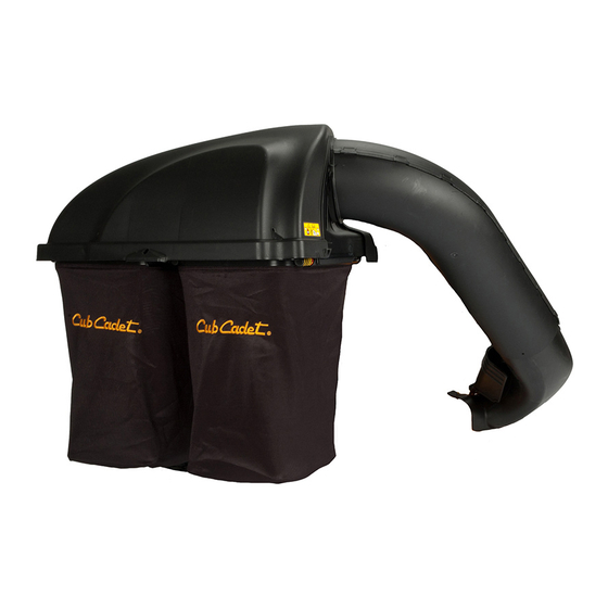
Twin Rear Bagger - Model No. 19A70005100
WARNING
READ AND FOLLOW ALL SAFETY RULES AND INSTRUCTIONS IN THIS MANUAL
BEFORE ATTEMPTING TO OPERATE THIS MACHINE.
FAILURE TO COMPLY WITH THESE INSTRUCTIONS MAY RESULT IN PERSONAL INJURY.
CUB CADET LLC, P.O. BOX 361131 CLEVELAND, OHIO 44136-0019
Printed In USA
FORM NO. 769-04695
12/16/2008
Advertisement

Summary of Contents for Cub Cadet 19A70005100
- Page 1 READ AND FOLLOW ALL SAFETY RULES AND INSTRUCTIONS IN THIS MANUAL BEFORE ATTEMPTING TO OPERATE THIS MACHINE. FAILURE TO COMPLY WITH THESE INSTRUCTIONS MAY RESULT IN PERSONAL INJURY. CUB CADET LLC, P.O. BOX 361131 CLEVELAND, OHIO 44136-0019 Printed In USA FORM NO. 769-04695...
-
Page 2: Table Of Contents
Visit us on the web at www.cubcadet.com ◊ Call a Customer Support Representative at (800) 965-4CUB ◊ Locate your nearest Cub Cadet Dealer at (877) 282-8684 ◊ Write us at Cub Cadet LLC • P.O. Box 361131 • Cleveland, OH • 44136-0019... -
Page 3: Safe Operation Practices
Important Safe Operation Practices WARNING! This symbol points out important safety instructions which, if not followed, could endanger the personal safety and/or property of yourself and others. Read and follow all instructions in this manual before attempting to operate this machine. Failure to comply with these instructions may result in personal injury. - Page 4 Use slow speed. Choose a low enough speed setting so General Service that you will not have to stop or shift while on the slope. Before cleaning, repairing, or inspecting, make certain the Tires may lose traction on slopes even though the brakes blade(s) and all moving parts have stopped.
- Page 5 2 — i ectiOn MpOrtant peratiOn ractices...
- Page 6 Contents of Carton Before beginning installation, remove all parts from the carton to make sure everything is present. Carton contents are listed below and shown in Fig. 3-1. Three hardware packs are included in this kit and are detailed on the following page. •...
- Page 7 CONTENTS OF HARDWARE PACK This grass collector kit is shipped with three loose hardware packs enclosed and one set of hardware included in the mounting bracket kit. Please check your hardware packs against the illustrations below. The quantities for each item is listed in parenthesis. Hardware Pack 689-00095 Hardware Pack 689-00091 723-04008A...
-
Page 8: Assembly & Installation
Assembly & Installation NOTE: References to left, right, front and rear of the tractor are from the operator’s position, unless otherwise stated. • Before assembly, place the tractor on a firm, level surface, disengage the PTO, stop the tractor engine and set the parking brake. - Page 9 Mount Assembly on Tractor Install the bagger hanger assembly onto the mounting assembly on the tractor by hooking it over the hitch plate between Install mounting assembly on tractor as follows: the two tabs. See Fig. 4-6. Slide the mounting bracket assembly along the frame rails of the tractor until the hooks in the mounting brackets align under the shoulder bolts on your tractor, as seen in Fig.
- Page 10 Installing the Weight Bar Assembling Remaining Bagger Components Install the weight bar onto the front of the tractor’s foot rest Now that the mounting brackets are assembled and are in place using two 710-3022 hex screws and 712-04065 hex flange lock on the tractor, follow these steps to assemble the remaining nuts from Hardware Pack 689-00095.
- Page 11 Make sure screen sits under the cover’s lip Figure 4-13 Figure 4-11 Install the bagger cover onto the bag support assembly, as seen in Fig. 4-12. The plastic cover goes inside of the two mounting tabs. Figure 4-14 Open Hood by pushing in on the rear, right-side tab with your right hand, as seen in 1 of Fig.
- Page 12 Install both bag assemblies with the tight mesh sides facing forward, onto the bag support brackets by inserting the front edge in first, as seen in 1 of Fig. 4-16, and setting the back edge down until it fits into the assembly (2). Figure 4-18 With the tractor’s discharge chute raised up and held open, install the chute elbow over the chute opening by placing...
- Page 13 Figure 4-20 Figure 4-22 With the bagger cover open, install the upper chute over the Secure the chute elbow to the tractor’s deck by hooking the chute adapter, and rest the top so that the chute support chute strap onto the ball pin installed earlier on the deck. sits in the upper chute groove.
-
Page 14: Operation
Operation Bagger Usage NOTE: When both grass bags are full, place the tractor on a firm, level surface, disengage the PTO, turn the tractor engine off and set the parking brake. Lift up the grass bag cover as instructed on Page 11 in Step 7. - Page 15 Notes...
- Page 16 19A70005100 Parts List...
-
Page 17: Parts List
Ref. Part Number Description 631-04295 Upper Chute Assembly 631-04292 Twin Bagger Cover Assembly 731-06497 Upper Chute Support 731-06504 Bagger Cover Screen 710-0276 Carriage Screw, 5/16-18 x 1.00” 710-3008 Hex Head Screw, 5/16-18 x .75” 711-0332 Clevis Pin, .50” Dia. 664-04090 Grass-bag Assembly 683-04481 Twin Bag Support Assembly... - Page 18 Notes...
-
Page 20: Warranty
Service completed by someone other than an authorized service The limited warranty set forth below is given by Cub Cadet LLC with respect to new merchandise purchased or leased and used in the United dealer.


Need help?
Do you have a question about the 19A70005100 and is the answer not in the manual?
Questions and answers