SFA SANIPUMP ZFS 71 Operation Manual
Grinder pump
Hide thumbs
Also See for SANIPUMP ZFS 71:
- Operation manual (107 pages) ,
- Operating & installation manual (64 pages)
Table of Contents
Advertisement
Quick Links
Advertisement
Table of Contents

Subscribe to Our Youtube Channel
Related Manuals for SFA SANIPUMP ZFS 71


Summary of Contents for SFA SANIPUMP ZFS 71
- Page 1 9030 02.2020 SANIPUMP ZFS 71 ® Grinder pump Operation manual...
-
Page 2: Table Of Contents
1. SAFETY ..............pg.4 1.1 Identifying the warning signs ...........pg.4 1.2 Personnel qualifications and training .......pg.5 1.3 Dangers from non-observance of the safety instructions ..pg.5 1.4 Safety-awareness at work ..........pg.5 1.5 Safety instructions for the customer/operator ....pg.5 1.6 Safety instructions for maintenance, inspection and assembly work .pg.5 1.7 Unauthorised re-equipping and spare-part production ..pg.6 1.8 Unauthorised modes of operation ........pg.6 2. -
Page 3: Safety
1. SAFETY WARNING This device can be used by children who are at least 8 years old and by people with reduced physical, sensory or mental capacities or those without knowledge or experience, if they are properly supervised or if they have been given instructions on safely using the device and the associated risks have been understood. -
Page 4: Personnel Qualifications And Training
It is imperative to observe signs that are attached directly to the machine (for example, rotational direction arrow, sign for fluid connections) and must be kept fully legible. 1.2 Personnel qualifications and training The personnel responsible for operation, maintenance, inspection and assembly have to have the corresponding qualifications for those types of work. -
Page 5: Unauthorised Re-Equipping And Spare-Part Production
Prior to initial (re-)start-up, you are to take heed of the points listed in the section Initial Operation. 1.7 Unauthorised re-equipping and spare-part production Re-equipment and modification of the machine are only permitted after consultation with the manufacturer. Original spare parts and accessories authorised by the manufacturer are all part of the safety strategy. -
Page 6: Range Of Application
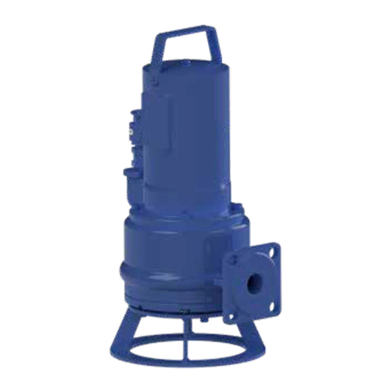
Materials Motor housing Motor shaft GG 20 1.4021 Pump housing Bearing flange GG 20 GG 20 Cutting flange Impeller 1.4112 GG 20 Cutting knife Other seals 1.4112 NBR, FPM Auxiliary bearing flange Floating-ring type shaft seal St 37-2 SiC (silicon carbide) 2.4 Range of application The submersible waste water pumps of the type series SANIPUMP ZFS 71 are used for the drainage of... -
Page 7: Transport And Temporary Storage
3. TRANSPORT AND TEMPORARY STORAGE On principle, the pumps SANIPUMP ZFS 71 should be lifted and/or transported using the eyelets on ® top or the handlebar designed for that purpose. Under no circumstances is the pump to be lifted on the power supply cable ! For temporary storage and conservation, it suffices if the pumps are stored in a cool, dry, frost-protected and dark place. - Page 8 - The switching device has to be installed outside the explosion- prone area! - The floater for the protection against dry running has to be installed in such a way, so that a decline of the water level below the bottom line of the motor housing is not possible. Further electrical installation is not necessary.
-
Page 9: Hydraulic System
Wiring diagram: MAINS 3~ 400 V/50 Hz Fuse Motor protection Thermal winding protection Control circuit Clipping circuit Motor relay 400 V 50 Hz Green/Yellow PE conductor Connection of the thermal winding cover : - Control loop : T1 and T2 must be connected in a switching device in such a way, that the following function is guaranteed: When the temperature sensors respond, the pump is switched off until the tempera-ture has dropped again. -
Page 10: Level Control System
- Sound out position of guide pipe frame for coupling pedestal, adjust coupling pedestal on shaft bottom and mount it with the heavy-duty dowels which are included in the delivery. - Install pressure pipe and valves in a tension-free manner. - Slip the guide pipe on the coupling pedestal, shorten it to correct length, slip on pipe clamp and tighten it for good. -
Page 11: Technical Modifications
Malfunction Cause Elimination 1. Motor is not - absence of line voltage or improper - check voltage supply line voltage rotating - incorrect connection - correct the connection - defective power cable - replacement (customer service) - defective/wrong capacitor - replacement (customer service) - impeller/cutting knife blocked - cleaning - activated motor protection... -
Page 12: Appendix A : Characteristic Curves
Appendix A : Characteristic curves Appendix B : Installation suggestions Fixed installation Portable installation Coupling pedestal Backflow preventer Guide piece Wedge-type flat slide valve Pipe clamp Lowering chain with clevis Flange elbow Supporting ring Guide pipe 5/4'' Pressure pipe... -
Page 13: Appendix C : Pump Dimensions
Appendix C : Pump dimensions Fixed installation Portable installation Adjustment values for cutting gap and pump hydraulics... -
Page 14: Appendix D : Sectional Drawing And List Of Spare Parts
Appendix D : Sectional drawing and list of spare parts... - Page 15 Pos. Art. Nr. Designation Quantity 17369 Motor complete SANIPUMP ZFS 71.1 S 230 V ® 17368 Motor complete SANIPUMP ZFS 71.1 T and ZFS 71.2 T 400 V ® 17370 Motor complete SANIPUMP ZFS 71.3 T and ZFS 71.4 T 400 V ®...
Need help?
Do you have a question about the SANIPUMP ZFS 71 and is the answer not in the manual?
Questions and answers