Advertisement
Quick Links
Advertisement

Related Manuals for Hunter Seville-Savoy 41768


Summary of Contents for Hunter Seville-Savoy 41768
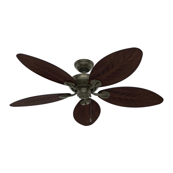
- Page 1 Installation Manual Manual de Instalación Manual de Instalação 41768 06/22/2016...
- Page 2 Introduction and Preparation ............................................... 3 Using This Manual ....................................................5 Installation ........................................................ 7 Operation and Troubleshooting ..............................................35 Introducción y preparación ................................................3 Uso de este Manual ....................................................5 Instalación ........................................................7 Operación y localización de fallas ..............................................35 Introdução e Preparação ................................................... 3 Usando este Manual ....................................................
-
Page 3: Before Installation
Congratulations! Before installing your fan, be sure you can do the following: Your new Hunter ceiling fan is an addition to your home or office that will • Locate the ceiling joist or other suitable support in the ceiling. provide comfort and reliable performance for many years. We are proud •... - Page 4 Hunter offers several accessories to complement your fan such as wall-mounted or remote speed controls and extension down-rods for ceilings higher than 2,4 m. To ensure wobble-free and stable performance, all Hunter fans use 2 cm inner-diameter pipe for extensions. Follow the instructions for use and installation included with the Hunter accessory.
-
Page 5: Como Usar Este Manual
How to Use This Manual: Screwdriver, Phillips- Wrench Be sure to read the entire manual before beginning installation and save head any extra parts for future use. This manual will help you install, operate, and maintain your new fan. These instructions are designed to make installation and assembly as simple and efficient as possible. - Page 6 WARNING! • To avoid possible electrical shock, before installing your fan, disconnect the power by turning off the circuit breakers to the outlet box and associated wall switch location. If you can not lock the circuit breakers in the off position, securely fasten a prominent warning device, such as a tag, to the service panel.
- Page 7 2,4 m >2,3 m Standard Mounting is the most common way to mount a ceiling Fan Mounting Options There are three different ways to mount your ceiling fan, fan. Standard mounting is recommended for ceilings 2,4 m or depending on your needs and the style of your ceiling. higher.
- Page 8 <2,4 m >2,3 m >2,3 m Flush Mounting is used when the ceiling is less than 2,4 m high Angle Mounting is especially useful for vaulted or angled ceilings. and fits closely to the ceiling. El montaje empotrado se emplea cuando el techo es menor que El montaje en ángulo es especialmente útil para techos 2,4 m (8 pies) y se ajusta estrechamente al techo.
- Page 9 If angle mounting, orient the ceiling plate with the arrows If you have a concrete ceiling, follow steps 1-5 before proceeding pointing toward the ceiling peak. to step 11. If you have a non-concrete ceiling, follow steps 6-10 before proceeding to step 11. Si está...
- Page 10 65 mm 50,8 mm 8 mm 8 mm For a concrete ceiling: Drive the M6 x 30 mm expansion anchors [a] into the holes Identify the supply mains in the ceiling and drill two holes using until the ends are flush with the ceiling. the ceiling plate [a] as a guide for measurement and accuracy.
- Page 11 Place the three black rubber isolators [a] into the round ceiling Thread the supply mains [a] through the center hole of the plate holes [b]. ceiling plate [b]. Coloque los tres aisladores de caucho [a] negros en los agujeros Pase los alambres de la alimentación de la red [a] a través del redondos de la placa de techo [b].
- Page 12 65 mm 50,8 mm 3,5 mm Align the Anchor bolts [a] with the oval slots in the ceiling For non-concrete ceilings: plate [b]. Push the Ceiling Plate onto the anchors [a] until the Drill two pilot holes into the wood support structure using the rubber isolators [c] are tight against the ceiling.
- Page 13 Place the three black rubber isolators [a] into the round ceiling Place a flat washer [a] on both of the wood screws [b]. plate holes [b]. Coloque los tres aisladores de caucho [a] negros en los agujeros Coloque una arandela plana [a] en ambos tornillos para redondos de la placa de techo [b].
- Page 14 Thread the supply mains [a] through the center hole of the Raise the ceiling plate [a] and align two opposing oval slots with ceiling plate [b]. the pilot holes [b]. Insert and tighten the two wood screws [c] with washers [d] to secure the ceiling plate [a] to the ceiling. Pase los alambres de la alimentación de la red [a] a través del Eleve la placa de techo [a] y alinee dos ranuras ovaladas agujero central de la placa de techo [b].
- Page 15 If you are using a standard or angle mounting style, follow steps WARNING! To reduce the risk of fire, electrical shock, or motor damage, do not lift 12-17 then skip to step 22. If you are using a flush mounting style, or carry the fan by the lead wires.
- Page 16 For standard or angle mounting: Slide the following parts onto the wires in this order: upper Pull the motor lead wires [a] through the pipe [b]. Screw the canopy [e], lower canopy [d], hanger bracket [c], Trilobular™ pipe into the fan motor [c] until tight then tighten the setscrew ball [b], and black wedge [a].
- Page 17 Place the black wedge [a] around the top of the pipe [b]. Align the openings in the wedge [a] with the holes in the pipe [b]. Insert the pin [c] through the holes to stabilize the wedge [a]. Coloque la cuña [a] negra alrededor de la parte superior del tubo Alinee las aberturas en la cuña [a] con los agujeros en el tubo [b].
- Page 18 Pull the Trilobular™ ball [a] up over the wedge [b] and allow the Insert the positioning screw [a] into the Trilobular™ ball [b] ends of the pin [c] to sit in the cutout area of the ball. and securely tighten. The top of the positioning screw [a] will rest on the wedge [c] and hold the ball in place.
- Page 19 For flush mounting: Slide the following parts onto the wires in this order: upper Remove the setscrew [a]. canopy [a], lower canopy [b], hanger bracket [c], and low profile adapter [d]. Para montaje empotrado: Deslice las siguientes partes sobre los alambres en este orden: Retire el tornillo de ajuste [a].
- Page 20 Place the low profile adapter [a] into the bottom of the hanger Align the three cutouts in the low profile adapter [a] with the bracket [b] allowing the flat sides of each to fit together. three holes in the top of the fan then install the three assembly screws [b].
- Page 21 Lift the fan and position the three tabs on the hanger bracket Temporarily thread an assembly screw [a] through the ceiling [a] with the three matching slots on the ceiling plate [b] then plate [b] into the hanger bracket [c] to prevent it from rotating. rotate counterclockwise to engage all three tabs.
- Page 22 Pull the supply mains [a] through the side of the hanger WARNING! To avoid possible electric shock, before wiring the fan, disconnect power bracket [b]. by turning off the circuit breakers to both the outlet box and its associated wall switch location. If you cannot lock the circuit breakers in the off position, securely fasten a prominent warning device, such as a tag, to the service panel.
- Page 23 This is the procedure for steps 26-29. Thread the end of each Earth wire [a] (green/yellow) to terminal [b] marked wire into the terminal block [a] on the hanger bracket [b], then secure each supply main [c] by tightening the small setscrews [d].
- Page 24 Neutral wire [a] (blue) to terminal [b] marked "N". Line wire [a] (brown) to terminal [b] marked "L". Alambre neutro [a] (azul) a terminal [b] marcado "N". Alambre de línea [a] (marrón) a terminal [b] marcado "L". O fio neutro [a] (azul) ao terminal [b] marcado com “N”. O fio de linha [a] (marrom) ao terminal [b] marcado com “L”.
- Page 25 An additional “L” terminal is provided for separate control of the Attach the plug connector [a] from the terminal [b] on the light kit if a separate line is provided for that purpose. hanger bracket [c] to the plug connector [d] on the fan wires [e].
- Page 26 Excess wire may be placed into the outlet box [a] for non- WARNING! Be sure no bare wire or wire strands are visible after making connections. concrete ceilings, or inside the hanger bracket [b] for concrete Failure to complete the following steps carefully could result in the fan ceilings.
- Page 27 Remove the temporary screw [a] that was placed through the Raise the lower canopy [a] over the hanger bracket [b] and hanger bracket [b] and ceiling plate [c] but leave the holes in align the three holes of the lower canopy [a] with the previously the hanger bracket [b] and ceiling plate [c] aligned.
- Page 28 Loosely install the three assembly screws [a] until all holes are Raise the upper canopy [a] and align the three holes on the properly aligned, then securely tighten each screw. upper canopy with the holes on the rim of the ceiling plate, then install and securely tighten the three assembly screws [b].
- Page 29 Remove blade mounting screws [a] and shipping bumpers [b] Follow steps 38-39 if your fan includes grommets [a]. Skip to step installed on the motor. Save the screws and discard the shipping 40 if your fan does not include grommets [a]. bumpers.
- Page 30 If your fan includes grommets [a], place them in the fan blade Attach the fan blade [a] to the blade iron [b] using three blade holes by hand. assembly screws [c]. Repeat for all blades. Securely tighten all screws. Proceed to step 41. Si su ventilador incluye arandelas [a], colóquelas manualmente Fije la paleta del ventilador [a] al soporte de paleta [b] usando en los agujeros de la paleta.
- Page 31 Attach the fan blade [a] to the blade iron [b] using three blade Loosely insert blade mounting screws [a] through the blade assembly screws [c]. Repeat for all blades. Securely tighten all iron [b] into the fan until all fan blades [c] are spaced and screws.
- Page 32 Partially thread two small assembly screws [a] into two of the Pull the upper plug connector [a] through the center of the three outermost holes on the switch housing mounting plate upper switch housing [b]. [b]. Enrosque parcialmente dos tornillos de montaje [a] pequeños Tire el conector superior [a] a través del centro de la caja en dos de los tres agujeros más exteriores en la placa de montaje superior del interruptor [b].
- Page 33 Place the keyhole slots in the upper switch housing [a] over the Install the remaining small assembly screw [a] into the third hole loosely threaded assembly screws [b] then rotate the switch and tighten all three securely. housing [a] counterclockwise until the screws are situated in the narrow end of keyhole.
- Page 34 Attach the plug connector [a] from the motor housing [b] to Place the lower switch housing assembly [a] over the upper the plug connector [c] on the lower switch housing [d]. switch housing [b] then align the holes of both housings and secure with three side screws [c].
-
Page 35: Operating Your Hunter Fan
Slide the reversing switch to the opposite position. Restart the fan. Operación de Su Ventilador Hunter Los interruptores de control se identifican por los símbolos siguientes: Ventilador Inversión... -
Page 36: Limpieza Y Mantenimiento
Pás pintadas ou esmaltadas devem ser limpas da mesma maneira que as partes polidas do ventilador. Caso necessite de peças ou assistência técnica entre em contato com seu revendedor Hunter Fan ou visite nosso site na WEB: http://www.hunterfanglobal.com. -
Page 37: Troubleshooting
Problem: Nothing happens; fan does not move. Problem: Excessive wobbling. Solution: Solution: • Turn power on, replace fuse, or reset breaker. • Use balancing kit included with fan. • Loosen canopy, check all wiring connections. • Tighten all screws. • Push reversing switch firmly left or right. •...
Need help?
Do you have a question about the Seville-Savoy 41768 and is the answer not in the manual?
Questions and answers