Table of Contents
Advertisement
Quick Links
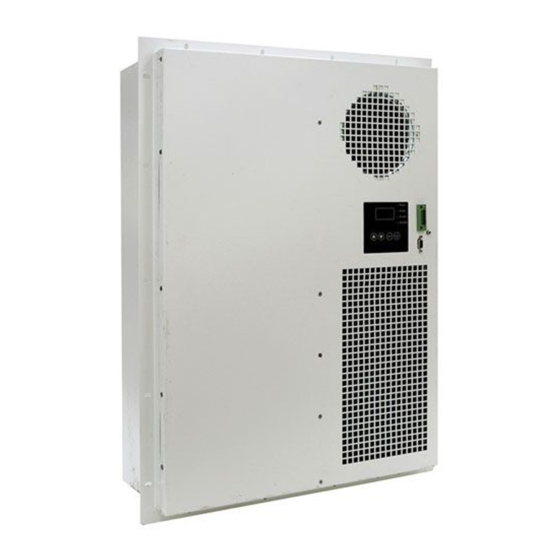
Air Conditioner
Instruction Manual
DELTA ELECTRONICS, INC.
USA
46101 Fremont Blvd, Fremont, CA 94538, U.S.A.
TEL : 1-510-668-5100
FAX : 1-510-668-0680
Cabinet-Thermal-Solutions@deltaww.com
Taiwan
252, SHANG YING ROAD, KUEI SAN
TEL : 886-(03)-3591968
TAOYUAN HSIEN 333, TAIWAN, R. O. C.
FAX : 886-(03)-3591991
Advertisement
Table of Contents

Related Manuals for Delta HECX1P Series


Summary of Contents for Delta HECX1P Series
- Page 1 Air Conditioner Instruction Manual DELTA ELECTRONICS, INC. 46101 Fremont Blvd, Fremont, CA 94538, U.S.A. TEL : 1-510-668-5100 FAX : 1-510-668-0680 Cabinet-Thermal-Solutions@deltaww.com Taiwan 252, SHANG YING ROAD, KUEI SAN TEL : 886-(03)-3591968 TAOYUAN HSIEN 333, TAIWAN, R. O. C. FAX : 886-(03)-3591991...
-
Page 2: Table Of Contents
Table of Contents 1. Version ...................... 1 2. Description ....................1 General .................... 1 Specification ..................1 Environmental Condition ..............2 Model Identification ................2 3. Installation ....................4 Outline Drawing ................4 Mounting Panel Cutout ..............7 4. Electrical Specification ................10 Function List ................... -
Page 3: Version
201602 Description 2.1 General This document outlines installation and characteristics of Delta HECX1P series air conditioners. Before installing the unit, please read this manual thoroughly, and follow the instructions contained within. HECX1P is a DC air conditioner with 48 VDC power input, designed for IP55 sealed outdoor utility cabinets to provide stable and optimum internal conditions for equipment, and prevent hot spots inside the cabinet. -
Page 4: Environmental Condition
Environmental Condition Description Specification Operating temperature -10°C ~ +55°C (14°F ~ 131°F) Storage temperature -40°C ~ +70°C (-40°F ~ 158°F) Humidity External air circuit: 0 ~ 100% RH Internal air circuit: 0 ~ 90% RH, Ingress protection level IEC60529 IP55 on external side Non-condensing Model Identification Model number logic is as follows:... - Page 5 AC 220V for roof AC 110V for door + heater AC 220V for door + heater AC 110V for roof + heater AC 220V for roof + heater I, J, K, L, M, N AC other DC 48V for door DC 48V for roof DC 48V for door + AC 110V heater DC 48V for door + AC 220V heater...
-
Page 6: Installation
Installation Outline Drawing HEC0500/0700PA mm (inch) (1) Material : Case SGCC Sheet (2) Finish : Power paint 75~120um, (3) Color : RAL 7035 (4) Dimension tolerance: X.X [X.XX] : ± 1.0mm [0.04”] X.XX [X.XXX] : ± 0.3mm [0.012”] Page 4... - Page 7 HEC0800/1000/1200/1500PB mm (inch) (1) Material : Case SGCC Sheet (2) Finish : Power paint 75~120um, (3) Color : RAL 7035 (4) Dimension tolerance: X.X [X.XX] : ± 1.0mm [0.04”] X.XX [X.XXX] : ± 0.3mm [0.012”] Page 5...
- Page 8 HEC0800/1000/1200PC (1) Material : Case SGCC Sheet mm (inch) (2) Finish : Power paint 75~120um, (3) Color : RAL 7035 (4) Dimension tolerance: X.X [X.XX] : ± 1.0mm [0.04”] X.XX [X.XXX] : ± 0.3mm [0.012”] Page 6...
-
Page 9: Mounting Panel Cutout
Mounting Panel Cutout HEC0500/0700PA Outside Gasket Inside Page 7... - Page 10 HEC0800/1000/1200/1500PB Outside Gasket Inside Page 8...
- Page 11 HEC0800/1000/1200PC Outside Gasket Inside Page 9...
-
Page 12: Electrical Specification
Electrical Specification Function List Cooling Display Rated Cooling Self-test Alarm Thermal Part No. Current /LED Voltage Capacity botton contact protection (L35/L35) Indication HEC0500PA DC 48V 500W 3.5A HEC0700PA DC 48V 700W 6.4A HEC0800PB DC 48V 800W 3.9A HEC1000PB DC 48V 1000W 5.6A HEC1200PB... - Page 13 If LED indicates alarm, the number of flashes helps identify root cause. Comp.: When the compressor is running normally, the LED will be solid green. If the system goes into self-test mode, the LED will flash green. Fan (In): ...
- Page 14 COM. and N.C(or N.O) PIN dry contact output close • Any alarms happening : COM. and N.C(or N.O) dry contact output open Parametric Setup Page 12...
- Page 15 System Default Setup Item System Parameter Default Range C - 70 d1.3 Inside over-temp. Setup d1.4 Auto Self Test Function Enable Enable/Disable Auto Self Test Period 1 Month 1 Month - 6 Month d1.6 Photo Coupler Normal Status Close Close/Open d1.7 Password...
- Page 16 Alarm Logs Flash Times LV1 Alarm LV2 Alarm Alarm Code (Power Led) Compressor 3-min Protection Compressor Power Protection Low-Temp Startup Protection Eva Temperature Protection Comp-out Temperature Protection Temperature Abnormal PWB Temperature Alarm Protection IPM Temperature Protection Amb Temperature Protection Amb Temperature Sensor Eva Temperature Sensor Cond Temperature Sensor...
- Page 17 • The target temperature is according to the system is too high but the higher than inside requirement. air conditioner is not • Please contact Delta or temperature. working • System failure. authorized Delta service agent. • Check the heating load of the •...
-
Page 18: Connection
Connection Power and Alarm Contact Connection HEC0800PB,HEC1000PB,HEC1200PB,HEC1500PB • Power Supply Connector Pin Description Cable wire size 2.5 mm (14 AWG) 2.5 mm (14 AWG) • Alarm Connector Pin Description Cable wire size Alarm+ COM.( 24 AWG) Alarm- N.C or N.O( 24 AWG) HEC0800PC,HEC1000PC,HEC1200PC,HEC0500PA,HEC0700PA •... -
Page 19: Maintenance
The heated air inside the cabinet will be cooled by the evaporator. Waste heat absorbed by the refrigerant will be dissipated through the condenser at the external side. HEC0500/0700PA, HEC0800/1000/1200/PC HEC0800/1000/1200/1500PB Maintenance SHUT DOWN the power before performing regular maintenance or component replacement. -
Page 20: Replacement
Replacement In case of abnormal operation, consult Delta or an authorized Delta service agent for assistance. MTBF The L10 Fan expected service life is to be at least 100,000 hours continuous operation at 40°C with 15 ~ 65% RH @ label rated voltage and cooling. - Page 21 Warning: Installation work and electrical wiring should be done only by qualified personnel in accordance with all applicable codes, standards and national wiring regulations. Use this unit only in the manner intended by the manufacturer. If you have questions, please contact the manufacturer. Install the air conditioner in accordance with the instructions in this installation manual.
-
Page 22: Packing & Shipping
Caution : Install the air conditioner on a wall or door strong enough to withstand the weight of the unit. Do not allow a child to mount onto the outdoor unit. Avoid placing any object on it. Do not block the air inlets or exits. Do not install the air conditioner at any place where there is a danger or flammable gas leakage.
Need help?
Do you have a question about the HECX1P Series and is the answer not in the manual?
Questions and answers