
Related Manuals for Delta RowCool HCH1CB0


Summary of Contents for Delta RowCool HCH1CB0
- Page 1 The power behind competitiveness Delta InfraSuite Precision Cooling RowCool Chilled Water Type (HCH1CB0 & HCH1DB0) User Manual www.deltapowersolutions.com...
- Page 2 Copyright © 2014 by Delta Electronics Inc. All Rights Reserved. All rights of this User Manual (“Man- by Delta Electronics Inc. (“Delta”). The Manual can only be applied to the operation or the use of this or usage of this Manual in whole or in part is prohibited without the prior written permission of Delta.
-
Page 3: Table Of Contents
Table of Contents Table of Contents Chapter 1 : Guide for Safe Operation ------------------------------------------------ 1 Safety Instructions -------------------------------------------------------------------- 1 Installation Instructions -------------------------------------------------------------- 1 Instructions for Use ------------------------------------------------------------------- 2 Chapter 2 : Introduction ------------------------------------------------------------------ 3 Product Introduction ------------------------------------------------------------------ 3 Functions and Features ------------------------------------------------------------- 3 Packing List ---------------------------------------------------------------------------- 4 Optional Accessories----------------------------------------------------------------- 5 Appearance ---------------------------------------------------------------------------- 6... - Page 4 Water Leakage Detector ---------------------------------------------------------- 27 Water Balance ----------------------------------------------------------------------- 28 PID Setting --------------------------------------------------------------------------- 29 Chapter 5 : Operation ---------------------------------------------------------------------32 LCD Display Hierarchy ------------------------------------------------------------ 32 Control Panel Operation ---------------------------------------------------------- 33 Status Screen and Main Menu -------------------------------------------------- 34 Account Authority and Login ----------------------------------------------------- 35 Operation Modes-------------------------------------------------------------------- 35 Shutdown ----------------------------------------------------------------------------- 36 Setting of Cooling Unit ------------------------------------------------------------- 37...
-
Page 5: Chapter 1 : Guide For Safe Operation
Chapter 1 Guide for Safe Operation Chapter 1 : Guide for Safe Operation Safety Instructions Please carefully read all chapters of the Manual before any installation, operation, and maintenance. To avoid personal injury and equipment damage, please be sure to oper- ate the product in accordance with the instructions in this Manual and the markings on the cabinet. -
Page 6: Instructions For Use
Instructions for Use The inner high voltage of the unit may be fatal! The inner components may have hidden lead to serious injury or death or equipment damage. Be sure to follow all the instructions and warnings contained in the Manual. When replacing the side panels or front or back doors, make sure there is no foreign mat- ter in the cabinet. -
Page 7: Chapter 2 : Introduction
Chapter 2 : Introduction Product Introduction The Delta InfraSuite RowCool Precision Cooling Unit (Chilled Water Type) adopts a parallel of the equipment. When installed in a data center, the untreated air will be sucked in from the rear of the cooling unit and the air, after treatment, will be released from the front of the unit to achieve the aim of cooling. -
Page 8: Packing List
Detection of heat load temperature Accurate monitor of the heat load temperature and humidity by remote temperature and humidity sensors. Leakage detection immediately inform the user of any water leakage so as to protect the safety of the equip- ment. Output and input dry contacts Heat insulation side panels Isolate the interference of outside temperature. -
Page 9: Optional Accessories
Use only for dustproof at trial operation by engineering personnel. Do not continue to use in normal operation. Optional Accessories For purchase of the following optional accessories, please contact service personnel. SNMP card: Use the Delta SNMP card to achieve the best compatibility. supports upper and lower water input modes. Heater assembly: function. -
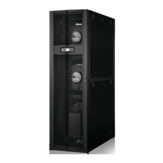
Page 10: Appearance
Appearance 1070 (Fig. 2-1: Appearance and dimensions) External Front/ cold aisle Rear/ hot aisle (Fig. 2-2: Front view) (Fig. 2-3: Bottom view) InfraSuite RowCool Precision Cooling – Chilled Water... - Page 11 Chapter 2 Introduction No. Description No. Description Upper drain hole Upper outlet hole of chilled water Upper Feed A power inlet hole Front door Upper Feed B power inlet hole Control panel Hole for water leakage detector Front door lock Lower Feed A power inlet hole Gradienter Lower Feed B power inlet hole...
- Page 12 Description Description Coil Fans Upper water inlet pipe Condensed water pan Joint of upper outlet water pipe Drain pump Filters Electric panel (Fig. 2-5: Main pipe components) Description Bypass value Inlet water temperature sensor Flow meter Outlet water temperature sensor Three-way ball valve and actuator InfraSuite RowCool Precision Cooling –...
-
Page 13: Piping System
Chapter 2 Introduction Piping System (Fig. 2-6: Pipe circuit diagram) No. Description No. Description Three-way ball valve Manual shut-off valve Lower drain connector Three-way connector Lower water supplement connector Outlet water temperature sensor Drain pump Inlet water temperature sensor Drain pump water pan Flow meter Lower inlet connector of chilled water Condensed water pan... -
Page 14: Control Panel
Control Panel System mode Standby (Fig. 2-7: Control panel) Item Description E.P.O. Emergency power off button. MAIN ON cates the unit is in installation mode. The yellow light indicates the unit runs in standby mode. The STANDBY WARNING The yellow light indicates alarm information. FAULT The red light indicates fault information. -
Page 15: Chapter 3 : Installation
Chapter 3 Installation Chapter 3 : Installation WARNING: 1. Only service personnel can perform the following installation procedures. No installation, damage and personal injury. 2. The high voltage in the equipment is potentially fatal! The inner components have poten- Installation Site When planning the installation site for the cooling unit, you must take the following into con- Environmental requirements: The installation site must allow the equipment to move in for maintenance, operation, and pipe repair. -
Page 16: Handling
It is suggested to preserve 1200mm for the front passage, 600mm for the rear passage and at least 300mm above the cabinet for pipe installation. If the pipeline adopts a lower connection Ceiling Above: 300mm Front Rear Wall 1,200mm 600mm Raised floor Raised floor ~ common floor Below: 300mm... -
Page 17: Positioning
Cabinet fasteners If the adjacent cabinets are Delta cabinets (MSR1110 and MSR2110), you may use con- fasteners (two at the front and two at the rear). You must remove the front and back doors before making the fastener connection. Refer to the following procedures: If the front door is locked, use the attached key to open it. - Page 18 Use the key to unlock the rear door, remove the earth wire, raise the door, and take it out. The rear door is of the split type and, if necessary, take down both doors. NOTE: Put the front and rear doors that have been removed in a safe place so as to avoid any equipment damage or personal injury due to collisions.
-
Page 19: Open The Front Door And Remove The Side Panels
Chapter 3 Installation L-type balance support Floor Expansion screws (Fig. 3-5: Installation of L-type balance support) Open the Front Door and Remove the Side Panels button and rotate the handle. To remove a side panel, use the same attached key to unlock the side panel, simultaneously press down the two door holders located at each side of the side panel and take the panel out. - Page 20 outside temperature and avoid condensed water. The hole diameter should be about 13mm. Upper chilled water inlet and outlet: 30mm Lower chilled water inlet and outlet: 130mm (Fig. 3-7: Upper and lower piping positions and dimensions) (unit: mm) (unit: mm) (Top view) (Bottom view) (Fig.
- Page 21 Chapter 3 Installation External Piping Inlet Precision Bypass Cooling Unit Outlet (Fig. 3-9: Suggested external piping) Description Description Thermometer Shut-off valve Ball valve Balance valve Pressure meter at the water inlet end as shown in Figure 3-9 in the water inlet maintenance, close the ball valve to let the chilled water go to the cooling unit via the branch so as to avoid shut-off loss.
- Page 22 Pipeline washing To guarantee cooling efficiency, you must purify the pipeline to filter out impurities and chemical substances. For pipeline washing, use a hose to create a short circuit to make the chilled water go directly from the inlet end to the return end without passing through The condensed water pipe has been connected in the lower part of the cabinet at one end, and you must pass the other end through the reserved hole at the bottom to drain the condensed water.
-
Page 23: Power Connection
Chapter 3 Installation Power Connection 3.8.1 Power WARNING: 1. The input power must conform to the rated value on the equipment nameplate. 2. The appliance of the power wires and backup connecting wires should conform PVC cord with a diameter of 10AWG (4.0mm ) and a temperature resistance of 105°C. - Page 24 Cable Power gland wires Cover plate Knocking piece (Fig. 3-12: Insertion of power wires) Use a screwdriver to loosen the screws of the terminal block and insert R, S, T, N, and G wires into it and lock them. (Fig. 3-13: Installation of power wires) Feed A Feed B (Fig.
- Page 25 Chapter 3 Installation Lower power feed The lower power feed is at the left lower part of the unit. Use nippers to remove the the accessory package, remove its nut, rotate and tighten the cable gland on the cover plate, and pass the power wires through it. (Fig.
- Page 26 3.8.2 Control box Front NETWORK RESET DISPLAY + - G INPUT OUTPUT NET UPS RS232 RS485 ALARM RACK REMOTE SENSOR (Fig. 3-17: Front of control box) No. Item Description SNMP This unit is compatible with an SNMP card (optional) and can be connected with a workstation so as to monitor and manage the sys- card slot chase separately) to connect the workstation and the SNMP card.
- Page 27 Chapter 3 Installation No. Item Description Remote At most, three remote temperature sensors (two are provided) can tempera- ture sensor them for you in installation for accurate detection of the temperature of heat loads. ports Remote Connects the remote temperature-humidity sensor (purchase sepa- temperature rately) for accurate detection of the temperature and humidity of humidity...
-
Page 28: Chapter 4 : Initial Startup
Chapter 4 : Initial Startup Pre Start-up Inspection WARNING: chapter. 2. The inner high voltage of this unit is potentially fatal! Make sure the input power has been disconnected before the following actions. 3. A startup without correctly completing 4.1 Pre Start-up Inspection may lead to serious personal injury or equipment damage! Please complete all the following inspections before implementing the initial startup proce- dures. -
Page 29: Power Supply
Only when it goes through manual mode, automatic mode, force mode or installation mode and returns to the standby mode, will the fans run at the minimum speed. After the display of the Delta trademark for three seconds, the LCD will enter the following status screen. - Page 30 RowCool standard operation environment conditions 90.0 80.0 Non-Operable 70.0 60.0 50.0 40.0 30.0 Operable 20.0 10.0 18 19 20 21 22 23 24 25 26 27 28 29 30 31 32 33 34 35 36 37 38 39 40 (Fig. 4-2: Standard Operation Environment Conditions) mode to reduce the humidity in the cabinet.
-
Page 31: Water Leakage Detector
Chapter 4 Initial Startup Manual exhaust valve of outlet water pipe Open (Fig. 4-3: Open the manual exhaust valve of outlet water pipe) NOTE: Refer to 3.7 External Piping. Water Leakage Detector This cooling unit is provided with a water leakage detector at the cabinet bottom when deliv- ered, which will be triggered to issue an alarm when in contact with water or liquid, reminding you to take proper measures. -
Page 32: Water Balance
Water Balance Branch balance valve Water inlet end Return water end Balance valve of return water end (Fig.4-4: Water balance) The program adopts a compensation method and adjusts the flow rate with the first (most remote) cooling unit as a reference point. The process needs at least three people to work at the same time. -
Page 33: Pid Setting
Chapter 4 Initial Startup Repeat the procedures branch balance valves. When all units are adjusted, record the opening of the balance valve of the return water PID Setting In light of different environmental conditions of data centers, the PID parameter values must 5.2 Control Panel Operation to get familiar with basic operation. - Page 34 9.00 0.55 0.000 Adjustment procedures The adjustment is made based on an open circuit method as follows: high, medium, and low openings of the three-way ball valve from the control panel. Adjust the three-way ball valve to the opening at half of the rated flow rate, which opening is too large (above 70%), reduce it to a medium opening (about 50%).
- Page 35 Chapter 4 Initial Startup Operation trial 2. Change the set point, record the stability time (reaching the set point of supply air tem- perature) via the SNMP interface, and observe if there is instability and temperature oscillation.
-
Page 36: Chapter 5 : Operation
Chapter 5 : Operation LCD Display Hierarchy Level 1 Level 1 System Status Alarm List Level 2 Main Menu Level 3 Level 3 Level 3 Level 3 *The user’s *The admin password Setting Administrator Status Power ON/OFF password required. required. Level 4 Level 4 Level 4... -
Page 37: Control Panel Operation
Chapter 5 Operation Control Panel Operation System Mode Standby The four buttons on the right of the control panel are used for operation and set-up: Button Description Goes back to previous screen or cancels current operation. Goes back to previous screen, moves up or increases number. to turn the page. -
Page 38: Status Screen And Main Menu
Status Screen and Main Menu Supply Air 50%RH 24.0 C Flow The LCD display will go off when the unit is idle. Press to wake up the backlight and dis- higher the fan speed. In the status screen, press to enter the Main Menu shown below. Power ON/OFF St a tu s Setting... -
Page 39: Account Authority And Login
Chapter 5 Operation Account Authority and Login The cooling unit has two accounts. The administrator has the highest authority and can alter all settings while the user can only alter the system setting. Input Password 0000 When you try to enter Setting or Administrator screen, a password prompt will occur. If no op- eration is performed for a long time after login, the login status will become invalid after the sys- tem becomes idle. -
Page 40: Shutdown
Operation Description mode Standby Path: Main Menu Power ON/ OFF Standby mode In the standby mode, the fans run at the minimum speed (40%), the three- way ball valve is fully closed and the chilled water goes through bypass without passing the coil. Manual mode Path: Main Menu Administrator... -
Page 41: Setting Of Cooling Unit
Chapter 5 Operation WARNING: In the standby mode, the unit is still in power-on status! In the standby mode, you must disconnect the input power or two circuits of feeds (Feed A & Feed B) to get the unit to fully power-off. standby mode, select Y and press STANDBY indicator lights, the unit is in the standby mode. - Page 42 ID (Number) Represent the number of the cooling unit connected in series and also the ID in the Mod- bus protocol. The default number is 1. If several cooling units are connected in series, you must designate each unit with a different number. Contrast Buzzer The default is ON.
-
Page 43: Set Point
Chapter 5 Operation Fault events 1. Emergency stop/ remote emergency stop 8. Abnormal remote sensor 9. Abnormal chilled water inlet/ outlet sensor 3. Leakage alarm/ leakage open-circuit alarm 4. Fire 11. Abnormal fan 5. Smoke 12. Abnormal three-way ball valve 6. -
Page 44: Controller Setting
5.7.3 Controller setting Path: Main Menu Setting Controller Force Mode Min Flow T 25 C P Gain Max Flow T 09.00 40 C I Gain Fan Step 0.550 D Gain Group Work 0.000 Auto Recover Intelligent Leak.Cut-Off Force Mode When the force mode is enabled, the fans will run at full speed and the three-way ball valve will fully open, which is generally used for performance testing or at a high heat load. -
Page 45: Setting Of Automatic Control Mode
Chapter 5 Operation Intelligent Display if the intelligent temperature control is enabled. This option only displays the status. You cannot change the setting. For change of setting, refer to 5.7.4 Setting of automatic control mode. Leak. Cut-Off Set if the unit will stop when the water leakage detector detects any leakage so as to pre- 5.7.4 Setting of automatic control mode Path: Main Menu Administrator... -
Page 46: Alarm Setting
5.7.5 Alarm setting Path: Main Menu Setting Set Alarm Sensor Alarm Actuator Alarm Out of Range Set Sensor Alarm, Actuator Alarm and Out-of-Range Alarm. If an item display is , this item is disabled. Press at this item, use to select , press item is enabled. -
Page 47: Inquiry Of System Status
Chapter 5 Operation Actuator alarm Path: Main Menu Setting Set Alarm Actuator Ball Valve Error Heater 1 Error Fan 1 Abnormal Heater 2 Error Fan 2 Abnormal Heater 3 Error Fan 3 Abnormal Humidifier Error Set the alarm on-off for ball valve, fans 1-3, heaters 1-3 and Out-of-Range alarm Path: Main Menu Setting... -
Page 48: Inquiry/ Elimination Of Event Log
Valve Com :100% Fan Com :100% Heater Com :----% Humidifier :----% Inquire about the system related information, including cooling capacity, supply air tem- perature and humidity, return air temperature and humidity, remote 1 temperature and humidity, remote 2 temperature, remote 3 temperature, air volume, chilled water inlet/ outlet temperature, , ball valve opening, ball valve command (set the ball-valve opening), fan command (set the fan speed), heater command, and humidi-... -
Page 49: Inquiry / Reset Of Running Hours
Chapter 5 Operation Path: Main Menu Status Run Hours System 2000h Fan 3 8000h Filter 720h Heater 1 8000h Fan 1 8000h Heater 2 8000h Fan 2 8000h Heater 3 8000h Humidifier 720h Ball Valve 8000h Inquire about the running hours of the system and components to assist you in evaluating the component status and judging the repair or replacement time. -
Page 50: Change Of System Type
After a component is changed, reset the operation time of Filter, Fans 1-3, Heater 1-3, Hu- or Ball valve. 5.7.9 Change of system type Path: Main Menu Administrator System Type Installation Type OPEN Set Admin PW ---- Clear Log Type as OPEN or CLOSE. -
Page 51: Chapter 6 : Maintenance And Cleaning
Chapter 6 Maintenance and Cleaning Chapter 6 : Maintenance and Cleaning Periodic inspection and cleaning of the cooling unit can guarantee the equipment to operate at the best status. The internal components such as fans and condensed water pan need periodic cleaning and inspec- tion. -
Page 52: Chapter 7 : Troubleshooting
Chapter 7 : Troubleshooting WARNING: System Troubleshooting: Abnormal Possible cause Elimination method phenomenon The fans cannot The power supply is Make sure the input voltage is within the start. abnormal. permissible range, the circuit breaker or switch is set at ON, and the cooling unit is correctly grounded. - Page 53 Chapter 7 Troubleshooting Abnormal Possible cause Elimination method phenomenon The operation Foreign matter is at- Clean and inspect the fans. noise is too high. tached to the fans or the damaged. The fan speed is too Check if the unit runs in the force mode or if high.
- Page 54 Abnormal Possible cause Elimination method phenomenon There is a water The humidity is too high. stain in the cabi- net. mode to reduce the internal humidity of the data center. The inlet water temper- Adjust the water supply temperature of the ature is too low.
- Page 55 Chapter 7 Troubleshooting Abnormal Possible cause Elimination method phenomenon It is unable to get The RS232 or RS485 Re-connect the connector. on-line via the connector is not cor- Modbus protocol. rectly connected. The Baud rate setting is abnormal or the ID does not match.
- Page 56 Alarm Possible cause Elimination method Information Fire Active Fire detection is trig- Inspect the environment and eliminate the gered. abnormality. Smoke Active Smoke detection is trig- Inspect the environment and eliminate the gered. abnormality. Comm Abnormal The CAN-Link port wiring Inspect the CAN-Link port wiring and con- is wrong or the unit ID is firm that the cooling units connected in...
- Page 57 Chapter 7 Troubleshooting Alarm Possible cause Elimination method Information Remote # T High 1) The environment tem- 1) Inspect if the environment temperature perature and humidity and humidity are within the operation Remote # T Low are abnormal. scope. 2) The alarm setting is 2) Inspect if the out-of-range alarm setting Remote # RH abnormal.
- Page 58 Alarm Possible cause Elimination method Information Leak Wire Open The water leakage detec- Inspect if the water leakage detector is tor is not correctly con- loose, in bad contact or broken. nected. NOTE: your dealer or customer service. InfraSuite RowCool Precision Cooling – Chilled Water...
- Page 59 Appendix 1 Appendix Model HCH1CB0 HCH1DB0 Phase/ Frequency/ Input Voltage 3 kW 57.5 kW 70 kW Air Volume 3162 l/s, 190 CMM, 6700 SCFM Rated Chilled Water Flow Rate 111.2 LPM Pressure Drop 110 kPa Rated Heating Capacity 10.8 kW Rated Humidifying Capacity 3 kg/hr Flow rate: 60 l/h...
-
Page 60: Appendix 2 : Periodic Inspection/ Maintenance List
Appendix 2 : Periodic Inspection/ Maintenance List Monthly Inspection/ Maintenance List Date: Model: Environment inspection The cooling unit is installed in? _____________________ Is it free of dust and surplus moisture? Yes / Is the cabinet appearance perfect without damage? Yes / Record the supply air temperature and humidity ________degree (s) ______ % Record the chilled water outlet temperature... - Page 61 Appendix 2 List of Periodic Maintenance Inspections Quarterly Inspection/ Maintenance List Date: Model: Cleaning: Clean the following components and use an air gun if necessary. Filters (replace them if necessary) Completed / Replaced Front and rear doors and side panels Completed Be sure to disconnect the input power before cleaning the following components.
-
Page 62: Appendix 3 : Glycol Correction Table
Appendix 3 : Glycol Correction Table Item Glycol type 1.00 0.96 0.89 0.81 0.73 0.65 Ethylene 1.00 1.04 1.11 1.17 1.25 1.34 NOTE: The correction parameters are based on the correction values under the following working conditions: pacity and water-side pressure drop. InfraSuite RowCool Precision Cooling –... -
Page 63: Appendix 4 : Warranty
Appendix 4 Warranty Appendix 4 : Warranty Seller warrants this product, if used in accordance with all applicable instructions, to be free from origi- nal defects in material and workmanship within the warranty period. If the product has any failure prob- lem within the warranty period, Seller will repair or replace the product at its sole discretion according to the failure situation. - Page 65 (HCH1CB0 HCH1DB0) www.deltapowersolutions.com...
- Page 67 -------------------------------------------------------- -------...
- Page 71 The power behind competitiveness InfraSuite www.deltagreentech.com.cn...
- Page 73 1070 Front/ cold aisle Rear/ hot aisle...
- Page 77 System mode Standby...
- Page 89 NETWORK RESET DISPLAY + - G INPUT OUTPUT NET UPS RS232 RS485 ALARM RACK REMOTE SENSOR...
- Page 90 AC24V VIN-B VIN-A OUTLET INLET LD DP WATER TEMP . TEMP. & HUMIDITY AC 24V 11 1 2...
- Page 92 Supply Air 50%RH 24.0 C Flow...
- Page 93 90.0 80.0 70.0 60.0 50.0 40.0 30.0 20.0 10.0...
- Page 96 Force Mode P Gain 09.00 I Gain 0.550 D Gain 0.000...
- Page 99 Setting Administrator Status Power ON/OFF System Manual Mode Setpoint Supply Air T/ Supply Air RH Fan Speed/ Ball Valve/ Humidifier/ Shutdown Humi/ Supply Air T/ Supply Air RH/ Humidifying stop/ Backlight/ Buzzer/ Total Alarm/ Return Air T/ Return Air RH/ Local Setting Chiller Pump/ Heater 1-3/ Main LED/ Standby LED Remote Ch1-4/ Air Volume/ Water...
- Page 100 System Mode Standby...
- Page 101 Supply Air 50%RH 24.0 C Flow Power ON/OFF St a tu s Setting Administrator...
- Page 102 Input Password 0000...
- Page 103 System Mode Standby Sure?
- Page 104 12/04/30 10:10:00 Language User PW ---- Contrast Unit Buzzer Delay On 0Sec Baud Rate 9600 Total Alarm Fault...
- Page 106 Supply Air T 24 C Supply Air RH...
- Page 107 Force Mode Min Flow T 25 C P Gain Max Flow T 09.00 40 C I Gain Fan Step 0.550 D Gain 0.000 Group Work Auto Recover Intelligent Leak.Cut-Off...
- Page 108 Intelligent...
- Page 109 Sensor Alarm Actuator Alarm Out of Range Return Sensor Remote Sensor 3 Supply Sensor Remote Sensor 4 Remote Sensor 1 Air Sensor Remote Sensor 2 Water In Sensor Water Out Sensor Flow Meter Leak SEN. High...
- Page 110 Ball Valve Error Heater 1 Error Fan 1 Abnormal Heater 2 Error Fan 2 Abnormal Heater 3 Error Fan 3 Abnormal Humidifier Error Return Air Return Air T High: ---- C RH High: ----% Return Air Return Air T Low: ---- C RH Low: ----% 12/04/30 Return Air T...
- Page 111 Valve Com :100% Fan Com :100% Heater Com :----% Humidifier :----% Number :66/66 12/01/01 10:10:00 <003>Exit Manual Mode...
- Page 112 System 2000h Fan 3 8000h Filter 720h Heater 1 8000h Fan 1 8000h Heater 2 8000h Fan 2 8000h Heater 3 8000h Humidifier 720h Ball Valve 8000h System Filter Sure? Fan 1 Fan 2...
- Page 113 Installation Type OPEN Set Admin PW ---- Clear Log Factory Setting Reset Component Set Run Hours Time 1100h...
- Page 123 _____________________ ________ ________ ________...
- Page 124 ______________________________________...
- Page 128 5013223500...
Need help?
Do you have a question about the RowCool HCH1CB0 and is the answer not in the manual?
Questions and answers