
Related Manuals for Hill-Rom Affinity Three


Summary of Contents for Hill-Rom Affinity Three
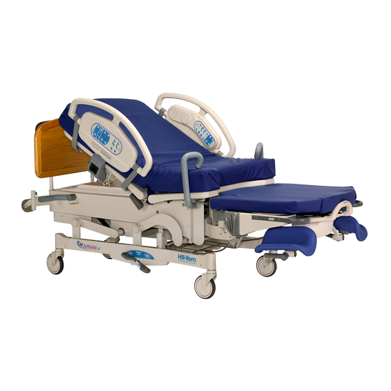
- Page 1 SERVICE MANUAL Affinity® Three Birthing Bed Affinity® Four Birthing Bed From Hill-Rom Product No. P3700 MAN272 REV 4...
- Page 3 SideCom® is a registered trademark of Hill-Rom Services, Inc. Slo-Blo® is a registered trademark of Littelfuse, Inc. Stow and Go® is a registered trademark of Hill-Rom Services, Inc. Torx® is a registered trademark of Acument Intellectual Property, LLC. Underwriters Laboratories Inc.® is a registered trademark of Underwriters Laboratories Inc.
- Page 4 NOTE: The back cover is a comprehensive list of Technical Support contact information for Hill-Rom. The product discussed in this manual may not be available in all of the countries listed. Page ii Affinity® Three Birthing Bed and Affinity® Four Birthing Bed...
-
Page 5: Table Of Contents
Table of Contents Chapter 1: Introduction Purpose ............1 - 1 Audience . - Page 6 Table of Contents Foot Up Malfunction ..........2 - 22 Foot Down Malfunction .
- Page 7 Table of Contents Line Voltage Fuses ..........4 - 45 Battery Assembly .
- Page 8 Table of Contents Electronics Module (Sheet 2 of 3) ........5 - 27 Electronics Module (Sheet 3 of 3) .
- Page 9 Table of Contents Push Handles........... . 5 - 110 Line Manager .
- Page 10 Table of Contents NOTES: Page x Affinity® Three Birthing Bed and Affinity® Four Birthing Bed Service Manual (MAN272 REV 4)
-
Page 11: Chapter 1: Introduction
Chapter 1 Introduction Purpose This manual provides requirements for the Affinity® Three Birthing Bed and Affinity® Four Birthing Bed normal operation and maintenance. It also includes parts lists (in chapter 5) for ordering replacement components. Audience This manual is intended for use by facility-authorized personnel only. Failure to observe this restriction can result in severe injury to people and serious damage to equipment. -
Page 12: Document Symbols
Document Symbols Chapter 1: Introduction Document Symbols This manual contains different typefaces and symbols to make the content easier to read and understand: • Standard text—used for regular data. • Boldface text—emphasizes a word or phrase. • NOTE:—sets apart special data or important instruction clarification. •... -
Page 13: Model Identification
Model Identification Chapter 1: Introduction Model Identification For bed model identification, see table 1-1 on page 1-3. Table 1-1. Model Identification Model Number Description P3700A Affinity® Three Birthing Bed P3700B Affinity® Four Birthing Bed, introduces Stow and Go® Retractable Foot Section P3700C Affinity®... - Page 14 Safety Tips Chapter 1: Introduction Brake and Steer Pedals Always keep the casters in the brake position when the bed is occupied. Patients often use the bed for support when getting in or out of bed, and serious injuries can result if the bed moves. After brakes are set, rock the bed gently to ensure that they are locked.
- Page 15 Safety Tips Chapter 1: Introduction CPR Release Only healthcare professionals should use the emergency CPR release. The two release handles are located under the head section of the bed near the seat section. To activate the CPR release, pull the handle away from the bed. Continue to pull out on the handle until the head section is flat.
- Page 16 Safety Tips Chapter 1: Introduction WARNING: Prop up the head section before removing the cotter pins and clevis pins. Failure to do so could result in personal injury or equipment damage. WARNING: You must use the 2" x 4" pieces of lumber to support the foot yoke. The foot yoke will fall during this procedure if not supported.
- Page 17 Follow the product manufacturer’s instructions. Failure to do so could result in personal injury or equipment damage. WARNING: Adhere to the Infection Control Policies and Procedures from Hill-Rom. Failure to do so could result in the spread of infection. WARNING: Powered bed mechanisms can cause serious injury.
- Page 18 Safety Tips Chapter 1: Introduction WARNING: Only facility-authorized personnel should perform preventive maintenance on the bed. Preventive maintenance performed by unauthorized personnel could result in personal injury or equipment damage. WARNING: Inspect the pivot point fasteners semi-annually. Failure to do so could result in personal injury or equipment damage.
- Page 19 Safety Tips Chapter 1: Introduction WARNING: The voltage in the electrical system presents an electrical shock hazard. Perform standard electrical service procedures before attempting service within the P.C. board enclosure. Adhere to all electrical safety precautions when servicing the bed’s electrical system. Failure to do so could result in personal injury or equipment damage.
- Page 20 Safety Tips Chapter 1: Introduction CAUTION: Remove the battery if the bed will not be in service for extended periods of time. Failure to do so could result in damage to the life of the battery, or damage to the bed. Contact the appropriate maintenance personnel. CAUTION: Do not position the head of the bed against a wall or beneath any fixtures.
- Page 21 Safety Tips Chapter 1: Introduction CAUTION: For shipping and storage, place the removed P.C. board in an antistatic protective bag. Failure to do so could result in equipment damage. CAUTION: Support the siderail during the removal procedure. Failure to do so could result in equipment damage.
-
Page 22: Warning And Caution Labels
Warning and Caution Labels Chapter 1: Introduction Warning and Caution Labels Figure 1-1. Warning and Caution Labels (Sheet 1 of 3) Page 1 - 12 Affinity® Three Birthing Bed and Affinity® Four Birthing Bed Service Manual (MAN272 REV 4) - Page 23 Warning and Caution Labels Chapter 1: Introduction Figure 1-2. Warning and Caution Labels (Sheet 2 of 3) Affinity® Three Birthing Bed and Affinity® Four Birthing Bed Page 1 - 13 Service Manual (MAN272 REV 4)
- Page 24 Warning and Caution Labels Chapter 1: Introduction Figure 1-3. Warning and Caution Labels (Sheet 3 of 3) Page 1 - 14 Affinity® Three Birthing Bed and Affinity® Four Birthing Bed Service Manual (MAN272 REV 4)
- Page 25 Warning and Caution Labels Chapter 1: Introduction NOTES: Affinity® Three Birthing Bed and Affinity® Four Birthing Bed Page 1 - 15 Service Manual (MAN272 REV 4)
- Page 26 Warning and Caution Labels Chapter 1: Introduction Page 1 - 16 Affinity® Three Birthing Bed and Affinity® Four Birthing Bed Service Manual (MAN272 REV 4)
-
Page 27: Chapter 2: Troubleshooting Procedures
(replacing or adjusting a part, seating a connector, etc.), perform the Function Checks. To verify the repair, perform the Final Actions after the Function Checks. If troubleshooting procedures do not isolate the problem, contact Hill-Rom Technical Support. Affinity® Three Birthing Bed and Affinity® Four Birthing Bed... -
Page 28: Test Equipment
Test Equipment Chapter 2: Troubleshooting Procedures Test Equipment You will need a digital or analog multimeter (VOM) with fine tip probes to troubleshoot the bed. WARNING: Refer to your VOM owner’s manual for complete and detailed information regarding the operation of your VOM. Failure to do so could result in personal injury or equipment damage. -
Page 29: Initial Actions
Initial Actions Chapter 2: Troubleshooting Procedures WARNING: Unplug the bed from its power source and disconnect the battery back-up before checking ohms/resistance measurements. Failure to disconnect line voltage to the bed can damage the VOM and cause equipment damage or personal injury. Initial Actions To gather information from operators concerning problems with the bed, use Initial Actions. -
Page 30: Function Checks
Function Checks Chapter 2: Troubleshooting Procedures Table 2-1. Quick Reference Problem/Solution Matrix Problem Solution Hilow Drive Operation Failures RAP 2.1 Hilow Up Malfunction RAP 2.2 Hilow Down Malfunction RAP 2.3 Head Drive Operation Failures RAP 2.4 Head Up Malfunction RAP 2.5 Head Down Malfunction RAP 2.6 Foot Drive Operation Failures... -
Page 31: Hilow System Functional Check
Function Checks Chapter 2: Troubleshooting Procedures 3. The lockout switch is in the “ON” (unlocked) position before proceeding with the function checks. Place the lockout switch in the “ON” (unlocked) position. Go to step 4. 4. Inspect the siderail cable connections to the logic control P.C. board cable. The cables are connected properly. -
Page 32: Trend-Like Position Functional Check
Adjust the Trend-Like position sensing switch (refer to procedure 4.9). If this solves the problem, go to “Final Actions” on page 2-10. Otherwise, contact Hill-Rom Technical Support. Page 2 - 6 Affinity® Three Birthing Bed and Affinity® Four Birthing Bed... -
Page 33: Head System Functional Check
Adjust the CPR release cables (refer to procedure 4.8). If this solves the problem, go to “Final Actions” on page 2-10. Otherwise, contact Hill-Rom Technical Support. Affinity® Three Birthing Bed and Affinity® Four Birthing Bed Page 2 - 7... -
Page 34: Foot System Functional Check
Adjust the foot limit switch (refer to procedure 4.7). If this solves the problem, go to “Final Actions” on page 2-10. Otherwise, contact Hill-Rom Technical Support. 5. Lower the foot section to the low position with the foot down switch. The foot drive stops when the foot lift arm is 1/4"... -
Page 35: Air System Functional Check
Replace the faulty rocker switch (refer to procedure 4.26). If this solves the problem, go to “Final Actions” on page 2-10. Otherwise, contact Hill-Rom Technical Support. Affinity® Three Birthing Bed and Affinity® Four Birthing Bed Page 2 - 9... -
Page 36: Final Actions
(refer to procedure 4.29), or for patient controls (refer to procedure 4.28). If this solves the problem, go to “Final Actions” on page 2-10. Otherwise, contact Hill-Rom Technical Support. 3. Perform the brake/steer performance check. Place the brake steer pedal into the brake position and then the steer position. -
Page 37: Hilow Drive Operation Failures
Replace the hilow motor (refer to procedure 4.3). If this solves the problem, go to “Final Actions” on page 2-10. Otherwise, contact Hill-Rom Technical Support. 5. Go to “Final Actions” on page 2-10. Affinity® Three Birthing Bed and Affinity® Four Birthing Bed... -
Page 38: Hilow Up Malfunction
2.2 Hilow Up Malfunction Chapter 2: Troubleshooting Procedures Hilow Up Malfunction The hilow motor does not raise the bed when the hilow up switch is activated. 1. The bed is plugged into the appropriate power source, and the lockout switch is off. ... - Page 39 8. Replace the hilow motor (refer to procedure 4.3). This solves the problem. Contact Hill-Rom Technical Support. 9. Go to “Final Actions” on page 2-10. Affinity® Three Birthing Bed and Affinity® Four Birthing Bed Page 2 - 13...
-
Page 40: Hilow Down Malfunction
2.3 Hilow Down Malfunction Chapter 2: Troubleshooting Procedures Hilow Down Malfunction The hilow motor does not lower the bed when the hilow down switch is activated. 1. The bed is plugged into the appropriate power source, and the lockout switch is off. ... - Page 41 8. Replace the hilow motor (refer to procedure 4.3). This solves the problem. Contact Hill-Rom Technical Support. 9. Go to “Final Actions” on page 2-10. Affinity® Three Birthing Bed and Affinity® Four Birthing Bed Page 2 - 15...
-
Page 42: Head Drive Operation Failures
Replace the head motor (refer to procedure 4.5). If this solves the problem, go to “Final Actions” on page 2-10. Otherwise, contact Hill-Rom Technical Support. 5. Go to “Final Actions” on page 2-10. Page 2 - 16 Affinity® Three Birthing Bed and Affinity® Four Birthing Bed... -
Page 43: Head Up Malfunction
2.5 Head Up Malfunction Chapter 2: Troubleshooting Procedures Head Up Malfunction The head motor does not raise the head section when the head up switch is activated. 1. The bed is plugged into the appropriate power source, and the lockout switch is off. - Page 44 9. Replace the head motor (refer to procedure 4.5). This solves the problem. Contact Hill-Rom Technical Support. 10. Go to “Final Actions” on page 2-10. Page 2 - 18 Affinity® Three Birthing Bed and Affinity® Four Birthing Bed...
-
Page 45: Head Down Malfunction
2.6 Head Down Malfunction Chapter 2: Troubleshooting Procedures Head Down Malfunction The head motor does not lower the head section when the head down switch is activated. 1. The bed is plugged into the appropriate power source, and the lockout switch is off. - Page 46 8. Replace the head motor (refer to procedure 4.5). This solves the problem. Contact Hill-Rom Technical Support. 9. Go to “Final Actions” on page 2-10. Page 2 - 20 Affinity® Three Birthing Bed and Affinity® Four Birthing Bed...
-
Page 47: Foot Drive Operation Failures
Replace the foot motor (refer to procedure 4.6). If this solves the problem, go to “Final Actions” on page 2-10. Otherwise, contact Hill-Rom Technical Support. 5. Go to “Final Actions” on page 2-10. Affinity® Three Birthing Bed and Affinity® Four Birthing Bed... -
Page 48: Foot Up Malfunction
2.8 Foot Up Malfunction Chapter 2: Troubleshooting Procedures Foot Up Malfunction The foot motor does not raise the foot section when the foot up switch is activated. 1. The bed is plugged into the appropriate power source, and the lockout switch is off. - Page 49 8. Replace the foot motor (refer to procedure 4.6). This solves the problem. Contact Hill-Rom Technical Support. 9. Go to “Final Actions” on page 2-10. Affinity® Three Birthing Bed and Affinity® Four Birthing Bed Page 2 - 23...
-
Page 50: Foot Down Malfunction
2.9 Foot Down Malfunction Chapter 2: Troubleshooting Procedures Foot Down Malfunction The foot motor does not lower the foot section when the foot down switch is activated. 1. The bed is plugged into the appropriate power source, and the lockout switch is off. - Page 51 8. Replace the foot motor (refer to procedure 4.6). This solves the problem. Contact Hill-Rom Technical Support. 9. Go to “Final Actions” on page 2-10. Affinity® Three Birthing Bed and Affinity® Four Birthing Bed Page 2 - 25...
-
Page 52: Hilow Up Malfunction (When The Foot Section Is Lowered)
Switch” on page 4-11 or “Foot Limit Switch” on page 4-22. If this solves the problem, go to “Final Actions” on page 2-10. Otherwise, contact Hill-Rom Technical Support. 3. Go to “Final Actions” on page 2-10. Page 2 - 26 Affinity®... -
Page 53: Brake Caster Malfunction
Otherwise, go to step 3. 3. Another part of the bed interferes with the brake mechanism. If the brakes still do not work, contact Hill-Rom Technical Support. 4. Take appropriate actions to eliminate the interference. This solves the problem. -
Page 54: Bed Air Surface Malfunction
Replace the logic control P.C. board (refer to procedure 4.23). If this solves the problem, go to “Final Actions” on page 2-10. Otherwise, contact Hill-Rom Technical Support. Page 2 - 28 Affinity® Three Birthing Bed and Affinity® Four Birthing Bed... - Page 55 10. Replace the cable or connectors from the logic control P.C. board to the air system control P.C. board. This solves the problem. Contact Hill-Rom Technical Support. 11. Go to “Final Actions” on page 2-10. 12. Disconnect the air connectors at the seat section. Activate the back inflate button, and test for air pressure on the patients left-hand side.
- Page 56 2.12 Bed Air Surface Malfunction Chapter 2: Troubleshooting Procedures 15. Pressure and suction are present at the connectors for all functions. Go to step 17. 16. Go to step 27. 17. Press any bed inflate button. The pump runs. ...
- Page 57 2.12 Bed Air Surface Malfunction Chapter 2: Troubleshooting Procedures NOTE: For high voltage checks, do not unplug the connectors. NOTE: Mains power is 120V AC if domestic, 230V AC if European. Go to step 24. 21. Set your VOM to measure V AC. At the air system control P.C. board connector P20, probe pin 1 (black) and pin 3 (white).
- Page 58 Replace the air system control P.C. board (refer to procedure 4.22). If this solves the problem, go to “Final Actions” on page 2-10. Otherwise, contact Hill-Rom Technical Support. Table 2-3. Solenoid Test—Air System Control P.C. Board Connector P22 Pin#...
- Page 59 2.12 Bed Air Surface Malfunction Chapter 2: Troubleshooting Procedures This solves the problem. Contact Hill-Rom Technical Support. 30. Go to “Final Actions” on page 2-10. Affinity® Three Birthing Bed and Affinity® Four Birthing Bed Page 2 - 33...
-
Page 60: Night Light Does Not Illuminate
Replace the logic control P.C. board (refer to procedure 4.23). If this solves the problem, go to “Final Actions” on page 2-10. Otherwise, contact Hill-Rom Technical Support. 5. Go to “Final Actions” on page 2-10. Page 2 - 34 Affinity®... -
Page 61: Siderail Mechanism Does Not Hold
“Final Actions” on page 2-10. Otherwise, continue to step 4. 4. Another part of the bed interferes with the siderail. If the siderail still does not work properly, contact Hill-Rom Technical Support. 5. Take appropriate actions to eliminate the interference. -
Page 62: Trend-Like Position Malfunction
2.15 Trend-Like Position Malfunction Chapter 2: Troubleshooting Procedures 2.15 Trend-Like Position Malfunction 1. If unable to place the bed in the Trend-Like position, press the hilow up switch to raise the bed to a higher position. Push down on the Trend-Like position release handle. -
Page 63: Battery Back-Up Malfunction
2.16 Battery Back-up Malfunction Chapter 2: Troubleshooting Procedures 2.16 Battery Back-up Malfunction 1. The battery has been properly charged and is providing power to the bed. Charge the battery. If this solves the problem, go to “Final Actions” on page 2-10. Otherwise, continue to step 2. 2. - Page 64 7. Replace the two batteries in the battery back-up assembly (refer to procedure 4.19). This solves the problem. Contact Hill-Rom Technical Support. Go to “Final Actions” on page 2-10. Page 2 - 38 Affinity® Three Birthing Bed and Affinity® Four Birthing Bed...
-
Page 65: Cpr Release Malfunction
Otherwise, go to step 3. 3. Another part of the bed interferes with the CPR release mechanism. If the head section still does not release, contact Hill-Rom Technical Support. 4. Take appropriate actions to eliminate the interference. This solves the problem. - Page 66 2.17 CPR Release Malfunction Chapter 2: Troubleshooting Procedures NOTES: Page 2 - 40 Affinity® Three Birthing Bed and Affinity® Four Birthing Bed Service Manual (MAN272 REV 4)
-
Page 67: Electrical System
Chapter 3 Theory of Operation Electrical System The following wiring diagrams detail the electrical circuits and the P.C. boards on the bed. Use these diagrams as troubleshooting aids. Affinity® Three Birthing Bed and Affinity® Four Birthing Bed Page 3 - 1 Service Manual (MAN272 REV 4) - Page 68 Electrical System Chapter 3: Theory of Operation Figure 3-1. Bed Wiring Diagram—P/N 63993 Refer to fold-out FO 3-1 and FO 3-2 at the rear of this manual. Page 3 - 2 Affinity® Three Birthing Bed and Affinity® Four Birthing Bed Service Manual (MAN272 REV 4)
- Page 69 Electrical System Chapter 3: Theory of Operation Figure 3-2. Logic Control P.C. Board—P/N 68121 Top Affinity® Three Birthing Bed and Affinity® Four Birthing Bed Page 3 - 3 Service Manual (MAN272 REV 4)
- Page 70 Electrical System Chapter 3: Theory of Operation Figure 3-3. Logic Control P.C. Board—P/N 68121 Bottom Page 3 - 4 Affinity® Three Birthing Bed and Affinity® Four Birthing Bed Service Manual (MAN272 REV 4)
- Page 71 Electrical System Chapter 3: Theory of Operation Figure 3-4. Mattress Driver P.C. Board P/N 41188 Affinity® Three Birthing Bed and Affinity® Four Birthing Bed Page 3 - 5 Service Manual (MAN272 REV 4)
- Page 72 Theory of Operation Chapter 3: Theory of Operation Theory of Operation A theory of operation is not available for the bed. Page 3 - 6 Affinity® Three Birthing Bed and Affinity® Four Birthing Bed Service Manual (MAN272 REV 4)
-
Page 73: Chapter 4: Removal, Replacement, And Adjustment Procedures
Chapter 4 Removal, Replacement, and Adjustment Procedures Tool and Supply Requirements To service the bed, the following tools and supplies are required: • Digital or analog multimeter (VOM) • Ratchet • T10 Torx® head bit • T25 Torx® head bit •... - Page 74 Tool and Supply Requirements Chapter 4: Removal, Replacement, and Adjustment Procedures • Tape measure • Marker pen • Bed jack • Bed stands, or (4) pieces of 2" x 4" x 32" lumber • Anti-seize lubricant • Blue Loctite® #242 •...
-
Page 75: Top Motor Cover
4.1 Top Motor Cover Chapter 4: Removal, Replacement, and Adjustment Procedures Top Motor Cover Tools required: Ratchet T25 Torx® head bit Removal 1. Set the brake/steer pedal to the brake position. 2. Ensure that the bed is out of the Trend-Like position. 3. - Page 76 4.1 Top Motor Cover Chapter 4: Removal, Replacement, and Adjustment Procedures Figure 4-1. Top Motor Cover Assembly Replacement To install the top motor cover (B), reverse the removal procedure. Page 4 - 4 Affinity® Three Birthing Bed and Affinity® Four Birthing Bed Service Manual (MAN272 REV 4)
-
Page 77: Bottom Motor Cover
4.2 Bottom Motor Cover Chapter 4: Removal, Replacement, and Adjustment Procedures Bottom Motor Cover Tools required: Ratchet T25 Torx® head bit Removal 1. Set the brake/steer pedal to the brake position. 2. Ensure that the bed is out of the Trend-Like position. 3. - Page 78 4.2 Bottom Motor Cover Chapter 4: Removal, Replacement, and Adjustment Procedures Figure 4-2. Bottom Motor Cover Assembly Replacement 1. To install the bottom motor cover (D), reverse the removal procedure. 2. Do the “Function Checks” on page 2-4. Page 4 - 6 Affinity®...
-
Page 79: Hilow Drive Motor Assembly
4.3 Hilow Drive Motor Assembly Chapter 4: Removal, Replacement, and Adjustment Procedures Hilow Drive Motor Assembly Tools required: T25 Torx® head bit Ratchet Needle nose pliers Bed stands, or (2) pieces of 2" x 4" x 32" lumber Removal 1. Set the brake/steer pedal to the brake position. 2. - Page 80 4.3 Hilow Drive Motor Assembly Chapter 4: Removal, Replacement, and Adjustment Procedures Figure 4-3. Bed Support Location CAUTION: Ensure that the night light is not damaged when the bed is being lowered. Failure to do so could result in equipment damage. 10.
- Page 81 4.3 Hilow Drive Motor Assembly Chapter 4: Removal, Replacement, and Adjustment Procedures Figure 4-4. Hilow Drive Motor Assembly 14. Using the needle nose pliers, remove two cotter pins (I) from the two clevis pins (J) that secure the hilow drive motor assembly (F) to the bed frame. Affinity®...
- Page 82 4.3 Hilow Drive Motor Assembly Chapter 4: Removal, Replacement, and Adjustment Procedures 15. Remove the two clevis pins (J) from the hilow drive motor assembly (F), and from the bed frame. 16. Remove the hilow drive motor assembly (F). Replacement 1.
-
Page 83: Hilow Limit Switch
4.4 Hilow Limit Switch Chapter 4: Removal, Replacement, and Adjustment Procedures Hilow Limit Switch Tools required: Small screwdriver Tape measure The hilow limit switch enables the correct maximum raised position of the bed. Its adjustment should be checked whenever the bed’s hilow system is serviced, such as when replacing the motor and during preventive maintenance. - Page 84 4.4 Hilow Limit Switch Chapter 4: Removal, Replacement, and Adjustment Procedures Figure 4-5. Hilow Limit Switch Adjustment 1. If the distance (A) is not 31" ± ½" (787.4 ± 12.7 mm), adjust the hilow limit switch by performing the following steps: a.
- Page 85 4.4 Hilow Limit Switch Chapter 4: Removal, Replacement, and Adjustment Procedures Figure 4-6. Logic Control P.C. Board—P/N 68121 Affinity® Three Birthing Bed and Affinity® Four Birthing Bed Page 4 - 13 Service Manual (MAN272 REV 4)
- Page 86 4.4 Hilow Limit Switch Chapter 4: Removal, Replacement, and Adjustment Procedures d. Use the hilow function to do as follows: • Non-Stow and Go beds—lower the bed until dimension B is 16" (406.4 mm) (see figure 4-5 on page 4-12). •...
- Page 87 4.4 Hilow Limit Switch Chapter 4: Removal, Replacement, and Adjustment Procedures Figure 4-7. Stow and Go® Foot Section—Hilow and Foot Switch Adjustment Affinity® Three Birthing Bed and Affinity® Four Birthing Bed Page 4 - 15 Service Manual (MAN272 REV 4)
-
Page 88: Head Drive Motor Assembly
4.5 Head Drive Motor Assembly Chapter 4: Removal, Replacement, and Adjustment Procedures Head Drive Motor Assembly Tools required: T25 Torx® head bit Ratchet Needle nose pliers Small wire cutters Bed stands, or (2) pieces of 2" x 4" x 32" lumber Removal 1. - Page 89 4.5 Head Drive Motor Assembly Chapter 4: Removal, Replacement, and Adjustment Procedures Figure 4-8. Head Drive Motor Assembly Affinity® Three Birthing Bed and Affinity® Four Birthing Bed Page 4 - 17 Service Manual (MAN272 REV 4)
- Page 90 4.5 Head Drive Motor Assembly Chapter 4: Removal, Replacement, and Adjustment Procedures 10. Unplug the head drive motor assembly (C) power cable (D) from logic control P.C. board connector P4. 11. Using the small wire cutters, cut the two cable ties (E) that secure the CPR cable assembly (F) to the head drive motor shaft (G).
-
Page 91: Foot Drive Motor Assembly
4.6 Foot Drive Motor Assembly Chapter 4: Removal, Replacement, and Adjustment Procedures Foot Drive Motor Assembly Tools required: T25 Torx® head bit Ratchet Needle nose pliers Bed stands, or (4) pieces of 2" x 4" x 32" lumber Removal 1. Set the brake/steer pedal to the brake position. 2. - Page 92 4.6 Foot Drive Motor Assembly Chapter 4: Removal, Replacement, and Adjustment Procedures 9. Deactivate the lockout function, and lower the foot section until the foot yoke is resting on the 2" x 4" pieces of lumber. 10. Using a ratchet and T25 Torx® head bit, remove the four screws (A) securing the electronics plate weldment (B) to the bed frame (see figure 4- 9 on page 4-20).
- Page 93 4.6 Foot Drive Motor Assembly Chapter 4: Removal, Replacement, and Adjustment Procedures 15. Remove the foot drive motor assembly (C). Replacement 1. To install the replacement foot drive motor assembly (C), reverse the removal procedure. 2. Do the “Function Checks” on page 2-4. Affinity®...
-
Page 94: Foot Limit Switch
4.7 Foot Limit Switch Chapter 4: Removal, Replacement, and Adjustment Procedures Foot Limit Switch Tools required: Small screwdriver Tape measure The foot limit switch adjustment should be performed whenever the bed’s foot system is serviced, such as when the foot motor is replaced, when the hilow switch is adjusted, and during preventive maintenance. - Page 95 4.7 Foot Limit Switch Chapter 4: Removal, Replacement, and Adjustment Procedures Figure 4-10. Checking the Foot Limit Switch NOTE: The green light indicates the maximum limit of the foot section's travel. If the green light is out, the foot section can travel farther until the light comes on or the foot section reaches its mechanical limits.
- Page 96 4.7 Foot Limit Switch Chapter 4: Removal, Replacement, and Adjustment Procedures Figure 4-11. Logic Control P.C. Board—P/N 68121 Page 4 - 24 Affinity® Three Birthing Bed and Affinity® Four Birthing Bed Service Manual (MAN272 REV 4)
- Page 97 4.7 Foot Limit Switch Chapter 4: Removal, Replacement, and Adjustment Procedures j. Check the gap (A) between the foot section left-hand lift arm (B) and the hilow left-hand lift arm (C) at the low position. Verify that the distance (A) is exactly ¼" (6.4 mm). k.
-
Page 98: Cpr Release
4.8 CPR Release Chapter 4: Removal, Replacement, and Adjustment Procedures CPR Release Tools required: Adjustable wrench Adjustment 1. Set the brake/steer pedal to the brake position. 2. Ensure that the bed is out of the Trend-Like position. 3. Using the hilow function, place the bed in a mid-height position. 4. - Page 99 4.8 CPR Release Chapter 4: Removal, Replacement, and Adjustment Procedures 9. Ensure that the CPR cables (A) are secured loosely with the cable tie (C) located on the head drive motor assembly. NOTE: The cable tie should be snug enough to secure the cable, but not tight enough to pinch the cable sheath.
-
Page 100: Trend-Like Position Sensing Switch
4.9 Trend-Like Position Sensing Switch Chapter 4: Removal, Replacement, and Adjustment Procedures Trend-Like Position Sensing Switch Tools required: 5/16" wrench There are two contact-type microswitches installed in the Trend-Like position mechanism. Only one switch requires adjustment. Proper adjustment of the Trend-Like position sensing switch (TS) keeps the bed from going too low while in the Trend-Like position. - Page 101 4.9 Trend-Like Position Sensing Switch Chapter 4: Removal, Replacement, and Adjustment Procedures Figure 4-13. Trend-Like Position Assembly 11. Ensure that the actuator arm (D) is fully activated. (The arm is fully activated when the switch makes an audible click.) 12. Using a 5/16" wrench, tighten the two screws (A) that secure the switch bracket (B) to the Trend-Like position release mechanism (E).
-
Page 102: Trend-Like Position Gas Spring
4.10 Trend-Like Position Gas Spring Chapter 4: Removal, Replacement, and Adjustment Procedures 4.10 Trend-Like Position Gas Spring Tools required: 11/16" wrench Split-ring removal tool WARNING: The head end of the main frame is supported by the two Trend-Like position gas springs. Any servicing will require that a support device be placed just beneath the head end of the main frame. - Page 103 4.10 Trend-Like Position Gas Spring Chapter 4: Removal, Replacement, and Adjustment Procedures Figure 4-14. Trend-Like Position Gas Spring Assembly Replacement 1. Spin the jam nut (D) all the way down on the new gas spring's rod end (F). 2. Thread the rod end (F) of the new gas spring (E) into the release assembly (G) until the plunger in the end of the rod just touches, or is no more than 1/16"...
-
Page 104: Head Section Gas Spring And Damper (Cpr Assist)
4.11 Head Section Gas Spring and Damper (CPR Assist) Chapter 4: Removal, Replacement, and Adjustment Procedures 4.11 Head Section Gas Spring and Damper (CPR Assist) Tools required: T25 Torx® head bit Ratchet Needle nose pliers Screwdriver Removal 1. Perform step 1 through step 5, step 8, and step 9 of “Head Drive Motor Assembly”... - Page 105 4.11 Head Section Gas Spring and Damper (CPR Assist) Chapter 4: Removal, Replacement, and Adjustment Procedures Figure 4-15. Head Section Gas Spring and Damper (CPR Assist) Replacement 1. To install the replacement head section gas spring (D) and damper (E), reverse the removal procedure.
-
Page 106: Foot Support Module
4.12 Foot Support Module Chapter 4: Removal, Replacement, and Adjustment Procedures 4.12 Foot Support Module Tools required: 5/32" Allen™ wrench 7/16" wrench T25 Torx® head bit Ratchet Removal 1. Set the brake/steer pedal to the brake position. 2. Ensure that the bed is out of the Trend-Like position. 3. - Page 107 4.12 Foot Support Module Chapter 4: Removal, Replacement, and Adjustment Procedures Replacement 1. To install the replacement foot support module (B), reverse the removal procedure. 2. Do the “Function Checks” on page 2-4. Adjustment 1. Do one of the following: a.
- Page 108 4.12 Foot Support Module Chapter 4: Removal, Replacement, and Adjustment Procedures Figure 4-17. Disassembled Foot Support Affinity® Three Birthing Bed Affinity® Four Birthing Bed Page 4 - 36 Affinity® Three Birthing Bed and Affinity® Four Birthing Bed Service Manual (MAN272 REV 4)
-
Page 109: Night Light And Cable Assembly
4.13 Night Light and Cable Assembly Chapter 4: Removal, Replacement, and Adjustment Procedures 4.13 Night Light and Cable Assembly Tools required: T25 Torx® head bit Ratchet Removal 1. Remove the top motor cover (refer to procedure 4.1). 2. Disconnect the night light and cable assembly (A) from logic control P.C. -
Page 110: Mattress Assembly
4.14 Mattress Assembly Chapter 4: Removal, Replacement, and Adjustment Procedures 4.14 Mattress Assembly Tools required: None Removal 1. Set the brake/steer pedal to the brake position. 2. Ensure that the bed is out of the Trend-Like position. 3. Carefully lift the mattress from the head end of the bed. CAUTION: Do not pull on the mattress material when unfastening the mattress retaining snaps. -
Page 111: Labor Grips
4.15 Labor Grips Chapter 4: Removal, Replacement, and Adjustment Procedures 4.15 Labor Grips Tools required: T25 Torx® head bit Ratchet Lubri-film spray (P/N 36958) External snap-ring removal tool Plug insertion tool (P/N 151085) Removal 1. Set the brake/steer pedal to the brake position. 2. - Page 112 4.15 Labor Grips Chapter 4: Removal, Replacement, and Adjustment Procedures 6. Using the external snap-ring removal tool, remove the external snap ring (D) from the pull handle. 7. Pull and hold the release (E) for the labor grip handle (F). 8.
-
Page 113: Foot Section (Lift Off)
4.16 Foot Section (Lift Off) Chapter 4: Removal, Replacement, and Adjustment Procedures 4.16 Foot Section (Lift Off) Tools required: None Removal 1. Pivot the foot mattress side panels (A) up (see figure 4-21 on page 4-42). 2. Grasp the mattress handles (B) or (G) located on both sides of the mattress. 3. - Page 114 4.16 Foot Section (Lift Off) Chapter 4: Removal, Replacement, and Adjustment Procedures Figure 4-21. Foot Section (Lift Off) Affinity® Three Birthing Bed Affinity® Four Birthing Bed Page 4 - 42 Affinity® Three Birthing Bed and Affinity® Four Birthing Bed Service Manual (MAN272 REV 4)
-
Page 115: Foot Section (Slide Off)
4.17 Foot Section (Slide Off) Chapter 4: Removal, Replacement, and Adjustment Procedures 4.17 Foot Section (Slide Off) Tools required: None Removal 1. Pivot the foot mattress side panels (A) up (see figure 4-21 on page 4-42). 2. Pull the foot section release handles (D) to release the latch mechanisms (E) from the channel slides (F) (see figure 4-22 on page 4-43). - Page 116 4.17 Foot Section (Slide Off) Chapter 4: Removal, Replacement, and Adjustment Procedures Replacement WARNING: Failure to properly mount the foot section to the yoke slide brackets could result in equipment damage or personal injury. 1. Grasp the mattress handles (B) located on both sides of the mattress (see figure 4-21 on page 4-42).
-
Page 117: Line Voltage Fuses
4.18 Line Voltage Fuses Chapter 4: Removal, Replacement, and Adjustment Procedures 4.18 Line Voltage Fuses Tools required: Small screwdriver Three mains fuses protect the high voltage circuit. Two fuses (line voltage fuses) are located in the fuse holder secured to the head end of the main frame. The third fuse is located on the air system control P.C. - Page 118 4.18 Line Voltage Fuses Chapter 4: Removal, Replacement, and Adjustment Procedures Figure 4-23. Fuse Location Replacement CAUTION: Ensure that the fuse housing is properly oriented for the voltage rating (110-120V or 220-240V) on the bed that you are servicing. Failure to do so could result in equipment damage.
-
Page 119: Battery Assembly
4.19 Battery Assembly Chapter 4: Removal, Replacement, and Adjustment Procedures 4.19 Battery Assembly Tools required: T25 Torx® head bit Ratchet Small screwdriver WARNING: Adhere to all electrical safety precautions when servicing the bed's electrical system. Failure to do so could result in personal injury or equipment damage. - Page 120 4.19 Battery Assembly Chapter 4: Removal, Replacement, and Adjustment Procedures Figure 4-24. Battery Assembly 9. Using a ratchet and T25 Torx® head bit, remove the screw (E) that secures the battery holder bracket (F) to the electronics plate weldment (G). 10.
- Page 121 4.19 Battery Assembly Chapter 4: Removal, Replacement, and Adjustment Procedures Replacement 1. To install the replacement battery fuse (I), reverse the removal procedures. 2. Do the “Function Checks” on page 2-4. Battery Charge Circuit Beds equipped with a 65345 logic control P.C. board and 67208 interface P.C. board may require adjustment of the battery charge circuit for optimal battery function.
- Page 122 4.19 Battery Assembly Chapter 4: Removal, Replacement, and Adjustment Procedures Figure 4-25. Logic Control P.C. Board—P/N 65345 Page 4 - 50 Affinity® Three Birthing Bed and Affinity® Four Birthing Bed Service Manual (MAN272 REV 4)
-
Page 123: Bed Surface Air System Assembly
4.20 Bed Surface Air System Assembly Chapter 4: Removal, Replacement, and Adjustment Procedures 4.20 Bed Surface Air System Assembly Tools required: Small wire cutters (2) ½" wrenches NOTE: When servicing the air system, it is important to ensure that the lumbar and seat inflate/deflate hoses are connected to the correct fittings on the air package. - Page 124 4.20 Bed Surface Air System Assembly Chapter 4: Removal, Replacement, and Adjustment Procedures Figure 4-26. Bed Surface Air System Assembly 10. Disconnect the transformer assembly power cable from air system control P.C. board (F) connector P19 (E) (see figure 4-27 on page 4-53). 11.
- Page 125 4.20 Bed Surface Air System Assembly Chapter 4: Removal, Replacement, and Adjustment Procedures Figure 4-27. Bed Surface Air System Cable Connections Replacement 1. To install the replacement air system, reverse the removal procedure. 2. Ensure that all air system functions work properly. 3.
-
Page 126: Air System Manifold Assembly
4.21 Air System Manifold Assembly Chapter 4: Removal, Replacement, and Adjustment Procedures 4.21 Air System Manifold Assembly Tools required: Phillips head screwdriver Removal 1. Remove the air system assembly (refer to procedure 4.20). 2. Disconnect the air hoses from the manifold assembly (A) (see figure 4-28 on page 4-54). -
Page 127: Air System Control P.c. Board Assembly
4.22 Air System Control P.C. Board Assembly Chapter 4: Removal, Replacement, and Adjustment Procedures 4.22 Air System Control P.C. Board Assembly Tools required: Phillips head screwdriver Needle nose pliers Removal 1. Set the brake/steer pedal to the brake position. 2. Ensure that the bed is out of the Trend-Like position. 3. - Page 128 4.22 Air System Control P.C. Board Assembly Chapter 4: Removal, Replacement, and Adjustment Procedures Figure 4-29. Air System Control P.C. Board Replacement 1. To install the replacement air system control P.C. board (B), reverse the removal procedures. 2. Ensure that the wiring connectors are firmly connected to the air system control P.C.
-
Page 129: Logic Control P.c. Board Assembly
4.23 Logic Control P.C. Board Assembly Chapter 4: Removal, Replacement, and Adjustment Procedures 4.23 Logic Control P.C. Board Assembly Tools required: Needle nose pliers Isopropyl alcohol SHOCK HAZARD: The voltage in the electrical system presents an electrical shock hazard. Perform standard electrical service procedures before attempting service within the P.C. - Page 130 4.23 Logic Control P.C. Board Assembly Chapter 4: Removal, Replacement, and Adjustment Procedures 8. Using the needle nose pliers, compress the locking tabs on the five logic control P.C. board mounting standoffs (B), pulling the logic control P.C. board (A) slightly up and over the locking tab on each mounting standoff. Figure 4-30.
- Page 131 4.23 Logic Control P.C. Board Assembly Chapter 4: Removal, Replacement, and Adjustment Procedures 1. Locate the P3 connector of the lockout switch cable. When used with a 65345 logic control P.C. board and 67208 interface P.C. board, the order of the four wires in the connector housing is red, red adjacent, and black, black adjacent (see figure 4-31 on page 4-59).
- Page 132 4.23 Logic Control P.C. Board Assembly Chapter 4: Removal, Replacement, and Adjustment Procedures 5. Push the connector shell (E) and the backshell (F) together until you hear a click and the locking tabs (D) are locked, holding the two parts of the connector housing firmly together.
-
Page 133: Transformer Assembly
4.24 Transformer Assembly Chapter 4: Removal, Replacement, and Adjustment Procedures 4.24 Transformer Assembly Tools required: T25 Torx® head bit Ratchet SHOCK HAZARD: The voltage in the electrical system presents an electrical shock hazard. Perform standard electrical service procedures before attempting service within the P.C board enclosure. Adhere to all electrical safety precautions when servicing the bed’s electrical system. - Page 134 4.24 Transformer Assembly Chapter 4: Removal, Replacement, and Adjustment Procedures Figure 4-33. Transformer Assembly Replacement 1. To install the replacement transformer assembly (A), reverse the removal procedures. 2. Ensure that the wiring connectors are firmly connected to the transformer assembly (A). 3.
-
Page 135: Auxiliary Transformer Assembly (Affinity® Three Bed)
4.25 Auxiliary Transformer Assembly (Affinity® Three Bed) Chapter 4: Removal, Replacement, and Adjustment Procedures 4.25 Auxiliary Transformer Assembly (Affinity® Three Bed) Tools required: T25 Torx® head bit Ratchet SHOCK HAZARD: The voltage in the electrical system presents an electrical shock hazard. - Page 136 4.25 Auxiliary Transformer Assembly (Affinity® Three Bed) Chapter 4: Removal, Replacement, and Adjustment Procedures Figure 4-34. Auxiliary Transformer Assembly Replacement 1. To install the replacement auxiliary transformer assembly (B), reverse the removal procedures. 2. Ensure that the wiring connectors (A) are firmly connected to the auxiliary transformer assembly (B).
-
Page 137: Lockout Switch Assembly
4.26 Lockout Switch Assembly Chapter 4: Removal, Replacement, and Adjustment Procedures 4.26 Lockout Switch Assembly Tools required: None SHOCK HAZARD: The voltage in the electrical system presents an electrical shock hazard. Perform standard electrical service procedures before attempting service within the P.C. board enclosure. Adhere to all electrical safety precautions when servicing the bed’s electrical system. - Page 138 4.26 Lockout Switch Assembly Chapter 4: Removal, Replacement, and Adjustment Procedures Figure 4-35. Lockout Switch Assembly Replacement 1. To install the replacement lockout switch assembly (B), reverse the removal procedures. 2. Ensure that the wiring connector (A) is firmly connected to the lockout switch assembly (B).
-
Page 139: Siderail Assembly
4.27 Siderail Assembly Chapter 4: Removal, Replacement, and Adjustment Procedures 4.27 Siderail Assembly Tools required: Small screwdriver Ratchet Needle nose pliers 7/16" socket WARNING: Adhere to all electrical safety precautions when servicing the bed’s electrical system. Failure to do so could result in personal injury or equipment damage. - Page 140 4.27 Siderail Assembly Chapter 4: Removal, Replacement, and Adjustment Procedures Figure 4-36. Siderail Assembly CAUTION: Ensure that the siderail does not drop when the pins are removed. Failure to do so could result in damage to the wiring going to the siderail.
-
Page 141: Patient Siderail (Inboard) P.c. Switch Board
4.28 Patient Siderail (Inboard) P.C. Switch Board Chapter 4: Removal, Replacement, and Adjustment Procedures 4.28 Patient Siderail (Inboard) P.C. Switch Board Tools required: T25 Torx® head bit Ratchet T10 Torx® head bit WARNING: Adhere to all electrical safety precautions when servicing the bed’s electrical system. - Page 142 4.28 Patient Siderail (Inboard) P.C. Switch Board Chapter 4: Removal, Replacement, and Adjustment Procedures Figure 4-37. Patient Siderail (Inboard) P.C. Switch Board 9. Using the ratchet and T10 Torx® head bit, remove the four screws (D) that secure the P.C. switch board (E) to the patient siderail cover (B). 10.
-
Page 143: Caregiver Siderail (Outboard) P.c. Switch Board
4.29 Caregiver Siderail (Outboard) P.C. Switch Board Chapter 4: Removal, Replacement, and Adjustment Procedures 4.29 Caregiver Siderail (Outboard) P.C. Switch Board Tools required: T25 Torx® head bit Ratchet T10 Torx® head bit WARNING: Adhere to all electrical safety precautions when servicing the bed’s electrical system. - Page 144 4.29 Caregiver Siderail (Outboard) P.C. Switch Board Chapter 4: Removal, Replacement, and Adjustment Procedures Figure 4-38. Caregiver Siderail (Outboard) P.C. Switch Board 11. Note the orientation of the wires and cable assemblies to ensure proper installation during the replacement procedure. 12.
-
Page 145: Central Braking System-P3700A Model Only
4.30 Central Braking System—P3700A Model Only Chapter 4: Removal, Replacement, and Adjustment Procedures 4.30 Central Braking System—P3700A Model Only Tools required: Phillips head screwdriver 1/8" drift punch 7/16" wrench Blue Loctite® #242 Hammer ½" wrench E-ring removal tool Anti-seize compound Needle nose pliers Marker pen (2) pieces of 2"... - Page 146 4.30 Central Braking System—P3700A Model Only Chapter 4: Removal, Replacement, and Adjustment Procedures Figure 4-39. Central Braking System Page 4 - 74 Affinity® Three Birthing Bed and Affinity® Four Birthing Bed Service Manual (MAN272 REV 4)
- Page 147 4.30 Central Braking System—P3700A Model Only Chapter 4: Removal, Replacement, and Adjustment Procedures c. Remove the spacers (X) on each side of the rocker arm (D). d. Remove the hairpin (G) and connector pin (H) that secures the metal brake strip (I) to the rocker arm (D). e.
- Page 148 4.30 Central Braking System—P3700A Model Only Chapter 4: Removal, Replacement, and Adjustment Procedures Replacement 1. To install the replacement central braking system mechanism, reverse the removal procedure with attention to the following: a. Ensure that the brake/steer strip (straight metal strap) and the brake strip (bent metal strap) are correctly assembled on their respective sides.
-
Page 149: Central Braking System-P3700B Model Only
4.31 Central Braking System—P3700B Model Only Chapter 4: Removal, Replacement, and Adjustment Procedures 4.31 Central Braking System—P3700B Model Only Tools required: Phillips head screwdriver 1/8" drift punch 7/16" wrench Blue Loctite® #242 Hammer ½" wrench E-ring removal tool Anti-seize compound Needle nose pliers Marker pen (2) pieces of 2"... - Page 150 4.31 Central Braking System—P3700B Model Only Chapter 4: Removal, Replacement, and Adjustment Procedures Figure 4-40. Central Braking System 7. Repeat step 6 for the head-end rocker arm. 8. Place the brake/steer pedal (A) into the neutral position. 9. Remove the headboard and the foot section from the bed. 10.
- Page 151 4.31 Central Braking System—P3700B Model Only Chapter 4: Removal, Replacement, and Adjustment Procedures 17. Repeat step 3 through step 17 for the opposite side. 18. Remove the detent mechanism assembly (T) from the cross channel. 19. Slide the brake rod support bracket (O) and bushing (U) from the end of the brake/steer pedal (A).
-
Page 152: Caster Assembly
4.32 Caster Assembly Chapter 4: Removal, Replacement, and Adjustment Procedures 4.32 Caster Assembly Tools required: T25 Torx® head bit 5/32" Allen™ wrench Ratchet 3/16" Allen™ wrench Bed jack Turpentine P3700A—The bed has two casters that have a braking feature. One of these casters also has a steer feature. - Page 153 4.32 Caster Assembly Chapter 4: Removal, Replacement, and Adjustment Procedures Figure 4-41. Caster Assembly Replacement 1. To install the replacement caster (C), reverse the removal procedure. NOTE: The new brake/steer caster could have 2 or 4 bolt holes in the stem. If the stem has a green dot on it, the green dot faces the head-end of the bed during installation.
- Page 154 4.32 Caster Assembly Chapter 4: Removal, Replacement, and Adjustment Procedures 3. Using the 5/32" Allen™ wrench, turn the setscrew (D) clockwise while swiveling the caster (C) about 2" from side to side, until you hear a light ratcheting sound. 4. Turn the setscrew (D) counterclockwise until the ratcheting stops. 5.
-
Page 155: Stow And Go® Foot Section Wire Form
4.33 Stow and Go® Foot Section Wire Form Chapter 4: Removal, Replacement, and Adjustment Procedures 4.33 Stow and Go® Foot Section Wire Form Tools required: Removal 1. Set the brakes. 2. Raise the bed to the full up position. 3. Raise the foot section to the full up position. WARNING: Failure to unplug the bed can cause personal injury or equipment damage. - Page 156 4.33 Stow and Go® Foot Section Wire Form Chapter 4: Removal, Replacement, and Adjustment Procedures Figure 4-42. Wire Form Removal Page 4 - 84 Affinity® Three Birthing Bed and Affinity® Four Birthing Bed Service Manual (MAN272 REV 4)
- Page 157 4.33 Stow and Go® Foot Section Wire Form Chapter 4: Removal, Replacement, and Adjustment Procedures Replacement 1. Do the “Removal” procedure in reverse order. 2. Do the “Function Checks” on page 2-4. Affinity® Three Birthing Bed and Affinity® Four Birthing Bed Page 4 - 85 Service Manual (MAN272 REV 4)
-
Page 158: Central Braking System-P3700B Model-New Brake Style
4.34 Central Braking System—P3700B Model—New Brake Style Chapter 4: Removal, Replacement, and Adjustment Procedures 4.34 Central Braking System—P3700B Model—New Brake Style Tools required: Phillips head screwdriver 1/8" drift punch 7/16" wrench Blue Loctite® #242 Hammer ½" wrench E-ring removal tool Anti-seize compound Needle nose pliers Marker pen... - Page 159 4.34 Central Braking System—P3700B Model—New Brake Style Chapter 4: Removal, Replacement, and Adjustment Procedures Figure 4-43. Central Braking System 7. Repeat step 6 for the head-end rocker arm. 8. Put the brake/steer pedal (A) into the neutral position. 9. Remove the headboard and the foot section from the bed. 10.
- Page 160 4.34 Central Braking System—P3700B Model—New Brake Style Chapter 4: Removal, Replacement, and Adjustment Procedures 17. Repeat step 2 through step 16 for the opposite side. 18. Remove the detent mechanism assembly (T) from the cross channel. 19. Slide the brake rod support bracket (O) and bushing (U) from the end of the brake/steer pedal (A).
-
Page 161: Caster Assembly-New Brake Style
4.35 Caster Assembly—New Brake Style Chapter 4: Removal, Replacement, and Adjustment Procedures 4.35 Caster Assembly—New Brake Style Tools required: T25 Torx® head bit 5/32" Allen™ wrench Ratchet 3/16" Allen™ wrench Bed jack Turpentine P3700B—The foot-left caster is a brake/steer caster and the remaining casters are brake casters. - Page 162 4.35 Caster Assembly—New Brake Style Chapter 4: Removal, Replacement, and Adjustment Procedures Figure 4-44. Caster Assembly Replacement 1. Do the removal procedure in reverse order. NOTE: For B/C/D model beds, the new brake/steer caster could have 2 or 4 bolt holes in the stem.
- Page 163 4.35 Caster Assembly—New Brake Style Chapter 4: Removal, Replacement, and Adjustment Procedures 2. Slowly turn the setscrew (D) clockwise—¼ turn at a time—as you swivel the caster (C) 360°, until you hear (or feel) a light ratcheting sound. 3. Turn the setscrew (D) counterclockwise 1/2 turn. 4.
-
Page 164: Line Manager
4.36 Line Manager Chapter 4: Removal, Replacement, and Adjustment Procedures 4.36 Line Manager Tools required: 7/16" wrench 1/2" wrench 1/2" socket and ratchet Removal 1. Set the brakes. 2. Raise the head section to 45°. WARNING: Failure to unplug the bed could cause injury. 3. - Page 165 4.36 Line Manager Chapter 4: Removal, Replacement, and Adjustment Procedures Replacement Do the removal procedure in reverse order. Affinity® Three Birthing Bed and Affinity® Four Birthing Bed Page 4 - 93 Service Manual (MAN272 REV 4)
-
Page 166: Push Handles
4.37 Push Handles Chapter 4: Removal, Replacement, and Adjustment Procedures 4.37 Push Handles Tools required: 7/16" wrench T25 Torx® screwdriver Removal 1. Set the brakes. WARNING: Failure to unplug the bed could cause injury. 2. Unplug the bed. 3. Remove the nut (A) from the bolt (B) (see figure 4-46 on page 4-94). 4. -
Page 167: Permanant Iv Pole-P3732A
4.38 Permanant IV Pole—P3732A Chapter 4: Removal, Replacement, and Adjustment Procedures 4.38 Permanant IV Pole—P3732A Tools required: T25 Torx® screwdriver Removal 1. Set the brakes. WARNING: Failure to unplug the bed could cause injury. 2. Unplug the bed. 3. Remove the two screws (A) from the IV pole (B) (see figure 4-47 on page 4-95). - Page 168 4.38 Permanant IV Pole—P3732A Chapter 4: Removal, Replacement, and Adjustment Procedures NOTES: Page 4 - 96 Affinity® Three Birthing Bed and Affinity® Four Birthing Bed Service Manual (MAN272 REV 4)
-
Page 169: Chapter 5: Parts List
Using the parts lists in this manual, identify the part number(s) you require. Find the product number and serial number on the product identification label (A) (see figure 5-1 on page 5-1). Figure 5-1. Product Identification Label Location Contact Hill-Rom Technical Support with the data that follows: • Customer account number •... - Page 170 Service Parts Ordering Chapter 5: Parts List To promptly order parts, request part prices and availability, or follow up on a service order, use this Hill-Rom fax number: 812-934-8472 Terms: • Net 30 days • F.O.B. Batesville, IN • Prepaid shipping charges added to invoice •...
-
Page 171: Exchange Policy
In some cases, the invoice accompanying the parts will show the full selling price (only for internal use at Hill-Rom). Do not confuse this price with your price. Do not return any parts without an RMA number. When parts/products have been requested to be returned, Hill-Rom will include an RMA packet with the parts/products shipment. - Page 172 Exchange Policy Chapter 5: Parts List NOTES: Page 5 - 4 Affinity® Three Birthing Bed and Affinity® Four Birthing Bed Service Manual (MAN272 REV 4)
-
Page 173: Warranty
No employee or representative of Hill-Rom is authorized to change these warranties in any way or grant any other warranty unless in writing and signed by a Hill-Rom officer. - Page 174 Warranty Chapter 5: Parts List NOTES: Page 5 - 6 Affinity® Three Birthing Bed and Affinity® Four Birthing Bed Service Manual (MAN272 REV 4)
-
Page 175: Recommended Spare Parts
Recommended Spare Parts Chapter 5: Parts List Recommended Spare Parts For a recommended spare parts list to service five or more units, see table 5-1 on page 5-7. Table 5-1. Recommended Spare Parts Part Number Quantity Description 450846048 Caster, 6" swivel 450848048 Caster, 8"... - Page 176 Recommended Spare Parts Chapter 5: Parts List NOTES: Page 5 - 8 Affinity® Three Birthing Bed and Affinity® Four Birthing Bed Service Manual (MAN272 REV 4)
-
Page 177: Caster Module
Caster Module—P3700A Chapter 5: Parts List Caster Module—P3700A Figure 5-2. Caster Module—P3700A Table 5-2. Caster Module—P3700A Item Number Part Number Quantity Description 450846048 Caster, 6" swivel (Affinity® Three Bed) 450848048 Caster, 8" swivel (Affinity® Three Bed) 450846648 Caster, 6" brake 450848648 Caster, 8"... - Page 178 Base Module—P/N 63951S (Sheet 1 of 2) (P3700A) Chapter 5: Parts List Base Module—P/N 63951S (Sheet 1 of 2) (P3700A) Figure 5-3. Base Module—P/N 63951S (Sheet 1 of 2) (P3700A) Page 5 - 10 Affinity® Three Birthing Bed and Affinity® Four Birthing Bed Service Manual (MAN272 REV 4)
- Page 179 Base Module—P/N 63951S (Sheet 1 of 2) (P3700A) Chapter 5: Parts List Table 5-3. Base Module—P/N 63951S (Sheet 1 of 2) (P3700A) Item Number Part Number Quantity Description 43878 Screw, button hd Torx® 41002 Spacer, rocker arm, 41269 Leg cover 32425 Set screw, hex socket hd 43030...
- Page 180 Base Module—P/N 63951S (Sheet 1 of 2) (P3700A) Chapter 5: Parts List Item Number Part Number Quantity Description 4098301 Washer, celcon 9026312 Bearing, DU 470850148 Base boss 9047714 Screw, shoulder, hex socket hd 4130848 End cap 44433 Brake pedal assembly, rh 4394602 End cap, cross tube, rh 43956PL...
- Page 181 Base Module—P/N 63951S (Sheet 1 of 2) (P3700A) Chapter 5: Parts List NOTES: Affinity® Three Birthing Bed and Affinity® Four Birthing Bed Page 5 - 13 Service Manual (MAN272 REV 4)
- Page 182 Base Module—P/N 63951S (Sheet 2 of 2) (P3700A) Chapter 5: Parts List Base Module—P/N 63951S (Sheet 2 of 2) (P3700A) Figure 5-4. Base Module—P/N 63951S (Sheet 2 of 2) (P3700A) Page 5 - 14 Affinity® Three Birthing Bed and Affinity® Four Birthing Bed Service Manual (MAN272 REV 4)
- Page 183 Base Module—P/N 63951S (Sheet 2 of 2) (P3700A) Chapter 5: Parts List Table 5-4. Base Module—P/N 63951S (Sheet 2 of 2) (P3700A) Item Number Part Number Quantity Description 60133 Hex rivnut 61653PL Clevis pin 6314308PL Clevis pin 63920 Hilow/Foot drive 61615 Rue ring cotter 9026304...
-
Page 184: Main Frame Module
Main Frame Module Chapter 5: Parts List Main Frame Module Figure 5-5. Main Frame Module Page 5 - 16 Affinity® Three Birthing Bed and Affinity® Four Birthing Bed Service Manual (MAN272 REV 4) - Page 185 Main Frame Module Chapter 5: Parts List Table 5-5. Main Frame Module Item Number Part Number Quantity Description 6391648 Cover, top motor 41250 Headboard bushing, oval 43878 Screw, button hd Torx® 41078 Headboard bushing, round 41243S48 Roller bumper and bracket assembly 25208 Axle 90016-06...
- Page 186 Main Frame Module Chapter 5: Parts List Item Number Part Number Quantity Description 4886801 Clevis pin (used starting Jan. 2001) 90260-48 Shoulder screw, hex socket hd, (used prior to Jan. 2001) 41263 Foot section link bar weldment 41413 Shroud, front 46772-48 Placenta basin 41111S...
- Page 187 Main Frame Module Chapter 5: Parts List Item Number Part Number Quantity Description 40497 Nut, keps Locknut 9006116 Screw 41073PL Trendelenburg activator 41087PL Trendelenburg follower 41135PL Trendelenburg cam 41079PL Trendelenburg stop 20802 Nut, keps 4540 Washer 9025910 Shoulder screw, hex socket hd, 5/16-18 x 5/8"...
-
Page 188: Siderail Module
Siderail Module Chapter 5: Parts List Siderail Module Figure 5-6. Siderail Module Page 5 - 20 Affinity® Three Birthing Bed and Affinity® Four Birthing Bed Service Manual (MAN272 REV 4) - Page 189 Siderail Module Chapter 5: Parts List Table 5-6. Siderail Module) Item Number Part Number Quantity Description 62625 Screw, pan hd, self-locking 4214101 Screw, pan hd Torx® hi-lo 6860002 Siderail cover, patient, rh 472730448 Screw, nylon 6503802 P.C. board assembly, caregiver siderail control, rh 6401301 Cable assembly, siderail jumper, 11...
- Page 190 Siderail Module Chapter 5: Parts List Item Number Part Number Quantity Description 3005804 Cable assembly, audio taper 6397501 Siderail arm, lh 63977 Upper rail 47256 Lever, siderail release 6397648 Siderail center weldment 67060 Seal, siderail 4096301 Knob, volume 6528601 P.C. board assembly, patient siderail control, lh 6397901 Siderail cover, patient, lh...
- Page 191 Siderail Module Chapter 5: Parts List Item Number Part Number Quantity Description 18890 E-ring (Used only with 6887248 siderail mounting bracket weldment and 68861PL latch pivot D-pin.) 35325 E-ring (Used only with 4725948 siderail mounting bracket weldment and 49192PL latch pivot pin.) 68861PL D-pin, latch pivot (Used only with 6887248 siderail mounting bracket...
-
Page 192: Electronics Module (Sheet 1 Of 3)
Electronics Module (Sheet 1 of 3) Chapter 5: Parts List Electronics Module (Sheet 1 of 3) Figure 5-7. Electronics Module (Sheet 1 of 3) Page 5 - 24 Affinity® Three Birthing Bed and Affinity® Four Birthing Bed Service Manual (MAN272 REV 4) - Page 193 Electronics Module (Sheet 1 of 3) Chapter 5: Parts List Table 5-7. Electronics Module (Sheet 1 of 3) Item Number Part Number Quantity Description 6342201 Power cord, detachable 110V 6342202 Power cord, detachable 220V, Australia/New Zealand 6342203 Power cord, Continental Europe 6342204 Power cord, UK/Ireland 6342205...
- Page 194 Electronics Module (Sheet 1 of 3) Chapter 5: Parts List Item Number Part Number Quantity Description 68121 P.C. board assembly, logic control (replaces 65345 logic control P.C. board assembly and 67208 interface P.C. board assembly) 63960 Transformer assembly 63944 Cable assembly, lockout 63981 Switch, lockout 66278...
-
Page 195: Electronics Module (Sheet 2 Of 3)
Electronics Module (Sheet 2 of 3) Chapter 5: Parts List Electronics Module (Sheet 2 of 3) Figure 5-8. Electronics Module (Sheet 2 of 3) Table 5-8. Electronics Module (Sheet 2 of 3) Item Number Part Number Quantity Description 40421 Cable tie mount 66053 Bracket, DC box mount 4214101... -
Page 196: Electronics Module (Sheet 3 Of 3)
Electronics Module (Sheet 3 of 3) Chapter 5: Parts List Electronics Module (Sheet 3 of 3) Figure 5-9. Electronics Module (Sheet 3 of 3) Page 5 - 28 Affinity® Three Birthing Bed and Affinity® Four Birthing Bed Service Manual (MAN272 REV 4) - Page 197 Electronics Module (Sheet 3 of 3) Chapter 5: Parts List Table 5-9. Electronics Module (Sheet 3 of 3) Item Number Part Number Quantity Description 43878 Screw, button hd Torx® 4759 Screw 41226PL Junction box top 6454701 PCB assembly, relay junction 6454702 PCB assembly, relay junction with UTV 66253...
-
Page 198: Electrical Cable Routing (Sheet 1 Of 2)
Electrical Cable Routing (Sheet 1 of 2) Chapter 5: Parts List Electrical Cable Routing (Sheet 1 of 2) Figure 5-10. Electrical Cable Routing (Sheet 1 of 2) Page 5 - 30 Affinity® Three Birthing Bed and Affinity® Four Birthing Bed Service Manual (MAN272 REV 4) - Page 199 Electrical Cable Routing (Sheet 1 of 2) Chapter 5: Parts List Table 5-10. Electrical Cable Routing (Sheet 1 of 2) Item Number Part Number Quantity Description 64002 Power entry module 66129 Night light and cable assembly 4142301S Trendelenburg mechanical limits cable assembly 43878 Screw, button hd Torx®...
-
Page 200: Electrical Cable Routing (Sheet 2 Of 2)
Electrical Cable Routing (Sheet 2 of 2) Chapter 5: Parts List Electrical Cable Routing (Sheet 2 of 2) Figure 5-11. Electrical Cable Routing (Sheet 2 of 2) Page 5 - 32 Affinity® Three Birthing Bed and Affinity® Four Birthing Bed Service Manual (MAN272 REV 4) - Page 201 Electrical Cable Routing (Sheet 2 of 2) Chapter 5: Parts List Table 5-11. Electrical Cable Routing (Sheet 2 of 2) Item Number Part Number Quantity Description 6394201 Cable assembly, battery-to-battery 44125 Plug (used on 230V beds only) 44128 Lockwasher, serrated (used on 230V beds only) 44126 Nut (used on 230V beds only)
-
Page 202: Sleep Deck Module (Sheet 1 Of 3)
Sleep Deck Module (Sheet 1 of 3) Chapter 5: Parts List Sleep Deck Module (Sheet 1 of 3) Figure 5-12. Sleep Deck Module (Sheet 1 of 3) Page 5 - 34 Affinity® Three Birthing Bed and Affinity® Four Birthing Bed Service Manual (MAN272 REV 4) - Page 203 Sleep Deck Module (Sheet 1 of 3) Chapter 5: Parts List Table 5-12. Sleep Deck Module (Sheet 1 of 3) Item Number Part Number Quantity Description 41059 Panel, V seat 40958 Snap, mattress retaining 35308 Finish washer 41060 Panel, U seat Hex locknut 41047 Washer, nylon...
- Page 204 Sleep Deck Module (Sheet 1 of 3) Chapter 5: Parts List Item Number Part Number Quantity Description 659660248 Labor grip weldment, rh 64006PL Pin, head/seat drive 65986 Screw 150751 Plug 34 (not shown) 151085 Plug insertion tool Page 5 - 36 Affinity®...
- Page 205 Sleep Deck Module (Sheet 1 of 3) Chapter 5: Parts List NOTES: Affinity® Three Birthing Bed and Affinity® Four Birthing Bed Page 5 - 37 Service Manual (MAN272 REV 4)
-
Page 206: Sleep Deck Module (Sheet 2 Of 3)
Sleep Deck Module (Sheet 2 of 3) Chapter 5: Parts List Sleep Deck Module (Sheet 2 of 3) Figure 5-13. Sleep Deck Module (Sheet 2 of 3) Page 5 - 38 Affinity® Three Birthing Bed and Affinity® Four Birthing Bed Service Manual (MAN272 REV 4) - Page 207 Sleep Deck Module (Sheet 2 of 3) Chapter 5: Parts List Table 5-13. Sleep Deck Module (Sheet 2 of 3) Item Number Part Number Quantity Description 65986 Screw 41061 Head deck 41344 Bumper plug 67088 Slide 6393901PL Handle weldment, CPR, lh 6393801 CPR handle, lh 35326...
-
Page 208: Sleep Deck Module (Sheet 3 Of 3)
Sleep Deck Module (Sheet 3 of 3) Chapter 5: Parts List Sleep Deck Module (Sheet 3 of 3) Figure 5-14. Sleep Deck Module (Sheet 3 of 3) Page 5 - 40 Affinity® Three Birthing Bed and Affinity® Four Birthing Bed Service Manual (MAN272 REV 4) - Page 209 Sleep Deck Module (Sheet 3 of 3) Chapter 5: Parts List Table 5-14. Sleep Deck Module (Sheet 3 of 3) Item Number Part Number Quantity Description 42575 Wireform, V seat 42576 Wireform, U seat 1012 Washer 9001828 Cap screw, hex hd 6724448 Foot section weldment, lift-off (used with 67415 yoke spacer and 4257401 cap...
- Page 210 Sleep Deck Module (Sheet 3 of 3) Chapter 5: Parts List Item Number Part Number Quantity Description 9023428 Locknut 6356601PL Bracket weldment, lh 63611 Screw, hex socket flat hd 18890 Truarc ring 61532PL Pivot stud 61534 Spring, non-corrosive torsion 63565 Pivot shaft 61525 Bearing...
- Page 211 Sleep Deck Module (Sheet 3 of 3) Chapter 5: Parts List NOTES: Affinity® Three Birthing Bed and Affinity® Four Birthing Bed Page 5 - 43 Service Manual (MAN272 REV 4)
-
Page 212: Label Module (Sheet 1 Of 4)-P3700A
Label Module (Sheet 1 of 4)—P3700A Chapter 5: Parts List Label Module (Sheet 1 of 4)—P3700A Figure 5-15. Label Module (Sheet 1 of 4)—P3700A Page 5 - 44 Affinity® Three Birthing Bed and Affinity® Four Birthing Bed Service Manual (MAN272 REV 4) - Page 213 65989 Label, battery caution 64004 Label, base frame 4583600 Label, foot clear, international 45836 Label, foot clear, Euro 64005 Label, base, Hill-Rom 45834 Label, foot support warning 4583400 Label, foot support warning, international 63995 Label, CPR 65382 Label, auxiliary light 65833 ...
-
Page 214: Label Module (Sheet 2 Of 4)-P3700A
Label Module (Sheet 2 of 4)—P3700A Chapter 5: Parts List Label Module (Sheet 2 of 4)—P3700A Figure 5-16. Label Module—Siderail (Sheet 2 of 4)—P3700A Page 5 - 46 Affinity® Three Birthing Bed and Affinity® Four Birthing Bed Service Manual (MAN272 REV 4) - Page 215 Label Module (Sheet 2 of 4)—P3700A Chapter 5: Parts List Table 5-16. Label Module—Siderail (Sheet 2 of 4)—P3700A Item Number Part Number Quantity Description 6396507 Overlay, caregiver, rh 6396503 Overlay, caregiver, rh 6396500 Overlay, caregiver, rh 6396501 Overlay, caregiver, rh 6396509 Overlay, caregiver, rh 6396697...
-
Page 216: Label Module (Sheet 3 Of 4)-P3700A
Label Module (Sheet 3 of 4)—P3700A Chapter 5: Parts List Label Module (Sheet 3 of 4)—P3700A Figure 5-17. Label Module (Sheet 3 of 4)—P3700A Table 5-17. Label Module (Sheet 3 of 4)—P3700A Item Number Part Number Quantity Description 6153501 Label, foot release, rh 63609 Label, slide off foot section caution 6360900... -
Page 217: Label Module (Sheet 4 Of 4)-P3700A
Label Module (Sheet 4 of 4)—P3700A Chapter 5: Parts List Label Module (Sheet 4 of 4)—P3700A Figure 5-18. Label Module (Sheet 4 of 4)—P3700A Table 5-18. Label Module (Sheet 4 of 4)—P3700A Item Number Part Number Quantity Description 67091 Grounding reliability 46770 Label CE 66859... -
Page 218: Foot Support Module-P3700A
Foot Support Module—P3700A Chapter 5: Parts List Foot Support Module—P3700A Figure 5-19. Foot Support Module—P3700A Page 5 - 50 Affinity® Three Birthing Bed and Affinity® Four Birthing Bed Service Manual (MAN272 REV 4) - Page 219 Foot Support Module—P3700A Chapter 5: Parts List Table 5-19. Foot Support Module—P3700A Item Number Part Number Quantity Description 6563703 Foot support module with calf support, 6563701S Foot support module, lh 6697001S Calf support module, lh 65700 Oilite® bushing 6572401PL Cam post weldment, lh 66966 Set screw, cup point 19124...
- Page 220 Foot Support Module—P3700A Chapter 5: Parts List Item Number Part Number Quantity Description 66430 Washer, plastic 65964 Snap ring 6580102 Mechlok®, rh 6572402PL Cam post weldment, rh 6604102 Heel cup, foot support, rh 6696502 Mechlok®, foot tilt, rh 656320248 Foot rest weldment, rh 6582802 Bellows, foot support, rh 6563704...
- Page 221 Foot Support Module—P3700A Chapter 5: Parts List NOTES: Affinity® Three Birthing Bed and Affinity® Four Birthing Bed Page 5 - 53 Service Manual (MAN272 REV 4)
-
Page 222: Calf Support Module-P3700A
Calf Support Module—P3700A Chapter 5: Parts List Calf Support Module—P3700A Figure 5-20. Calf Support Module—P3700A Page 5 - 54 Affinity® Three Birthing Bed and Affinity® Four Birthing Bed Service Manual (MAN272 REV 4) - Page 223 Calf Support Module—P3700A Chapter 5: Parts List Table 5-20. Calf Support Module—P3700A Item Number Part Number Quantity Description 68117 Knob assembly, calf support 37145 Lock stud 37146 Knob stud 8651 As required Loctite® #262 3714463 Knob 66975 Threaded insert 38677 Roll pin 67258 Ring, retaining, internal...
-
Page 224: Air Module
Air Module Chapter 5: Parts List Air Module Figure 5-21. Air Module Page 5 - 56 Affinity® Three Birthing Bed and Affinity® Four Birthing Bed Service Manual (MAN272 REV 4) - Page 225 Air Module Chapter 5: Parts List Table 5-21. Air Module Item Number Part Number Quantity Description 4698031 Air hose 46980-35 Air hose, lumbar seat, rh 19124 Cable tie Locknut 90016-40 Cap screw, hex hd 66135 Transformer and cable assembly, 220V 64008 Bracket, transformer mount—220V 41466...
-
Page 226: Headboard-Wood Style
Headboard—Wood Style Chapter 5: Parts List Headboard—Wood Style Figure 5-22. Headboard Table 5-22. Headboard Item Number Part Number Quantity Description 43878 Screw, button hd Torx® 37664 Clip, IV 31773 Screw 40995 Handle weldment, headboard 165456 Weldment, headboard, w/o handles 42600 Plug 42588 Grip, handle, foam... -
Page 227: Caster Module-P3700B/C
Caster Module—P3700B/C Chapter 5: Parts List Caster Module—P3700B/C Figure 5-23. Caster Module—P3700B/C Table 5-23. Caster Module—P377B/C Item Number Part Number Quantity Description 45084-6648 Caster, 6" brake 450846448 Caster, 6" brake/steer Affinity® Three Birthing Bed and Affinity® Four Birthing Bed Page 5 - 59 Service Manual (MAN272 REV 4) -
Page 228: Base Module-P3700B/C (Sheet 1 Of 2)
Base Module—P3700B/C (Sheet 1 of 2) Chapter 5: Parts List Base Module—P3700B/C (Sheet 1 of 2) Figure 5-24. Base Module—P3700B/C (Sheet 1 of 2) Page 5 - 60 Affinity® Three Birthing Bed and Affinity® Four Birthing Bed Service Manual (MAN272 REV 4) - Page 229 Base Module—P3700B/C (Sheet 1 of 2) Chapter 5: Parts List Table 5-24. Base Module—P3700B/C (Sheet 1 of 2) Item Number Part Number Quantity Description 152317 Top, orange pedal 70731 Top, green pedal 70780 Bottom, orange pedal 152316 Bottom, green pedal 142634 Brake link, foot, rh 152893...
- Page 230 Base Module—P3700B/C (Sheet 1 of 2) Chapter 5: Parts List Item Number Part Number Quantity Description 43949 Detent plunger 43952 Detent mechanism housing 152801S Detent mechanism assembly 43951 Pin, grove 44350 Clevis pin Page 5 - 62 Affinity® Three Birthing Bed and Affinity® Four Birthing Bed Service Manual (MAN272 REV 4)
- Page 231 Base Module—P3700B/C (Sheet 1 of 2) Chapter 5: Parts List NOTES: Affinity® Three Birthing Bed and Affinity® Four Birthing Bed Page 5 - 63 Service Manual (MAN272 REV 4)
-
Page 232: Base Module-P3700B/C (Sheet 2 Of 2)
Base Module—P3700B/C (Sheet 2 of 2) Chapter 5: Parts List Base Module—P3700B/C (Sheet 2 of 2) Figure 5-25. Base Module—P3700B/C (Sheet 2 of 2) Page 5 - 64 Affinity® Three Birthing Bed and Affinity® Four Birthing Bed Service Manual (MAN272 REV 4) - Page 233 Base Module—P3700B/C (Sheet 2 of 2) Chapter 5: Parts List Table 5-25. Base Module—P3700B/C (Sheet 2 of 2) Item Number Part Number Quantity Description 6314308 Clevis pin 63920 Hilow foot drive motor 44352 Cotter pin 61653 Clevis pin 142933 Intermediate frame weldment 68188 Bushing 40827...
-
Page 234: Sleep Deck-P3700B/C
Sleep Deck—P3700B/C Chapter 5: Parts List Sleep Deck—P3700B/C Figure 5-26. Sleep Deck—P3700B/C Page 5 - 66 Affinity® Three Birthing Bed and Affinity® Four Birthing Bed Service Manual (MAN272 REV 4) - Page 235 Sleep Deck—P3700B/C Chapter 5: Parts List Table 5-26. Sleep Deck—P3700B/C Item Number Part Number Quantity Description 42575 V-cut wire form 42576 U-cut wire form 142631 Lift handle, lh 142632 Lift handle, rh 49521 Screw 159181 Latch weldment, lh 159182 Latch weldment, rh 9001828 Screw 1012...
- Page 236 Sleep Deck—P3700B/C Chapter 5: Parts List Item Number Part Number Quantity Description 145225 Ramp, rh 145287 Ramp guide, rh 145275 Ramp guide, lh 35072 Shoulder screw 4648501 Setscrew 143463 Underframe mounting subassembly 143528 Mattress hook 0010220012 Flat washer 0010040018 Lock nut, nylon insert 0010330032 Screw, truss head Page 5 - 68...
- Page 237 Sleep Deck—P3700B/C Chapter 5: Parts List NOTES: Affinity® Three Birthing Bed and Affinity® Four Birthing Bed Page 5 - 69 Service Manual (MAN272 REV 4)
-
Page 238: Foot Support Module-P3700B/C
Foot Support Module—P3700B/C Chapter 5: Parts List Foot Support Module—P3700B/C Figure 5-27. Foot Support Module—P3700B/C Page 5 - 70 Affinity® Three Birthing Bed and Affinity® Four Birthing Bed Service Manual (MAN272 REV 4) - Page 239 Foot Support Module—P3700B/C Chapter 5: Parts List Table 5-27. Foot Support Module—P3700B/C Item Number Part Number Quantity Description not shown 148944 Foot support, complete, lh not shown 148945 Foot support, complete, rh 62959 Foot support handle 69391 Screw 43394 Clevis pin 60086 Screw 65829...
- Page 240 Foot Support Module—P3700B/C Chapter 5: Parts List Item Number Part Number Quantity Description 143010 Bellows, foot support, rh 143225 Release handle weldment, rh 6696502 Mechlok®, foot tilt, rh 145103 Kit, bellows assembly, rh (includes 4, 20, and 32) 145104 Kit, bellows assembly, lh (includes 4, 20, and 26) Not shown 155065S...
- Page 241 Foot Support Module—P3700B/C Chapter 5: Parts List NOTES: Affinity® Three Birthing Bed and Affinity® Four Birthing Bed Page 5 - 73 Service Manual (MAN272 REV 4)
-
Page 242: Calf Support Module-P3700B/C/D
Calf Support Module—P3700B/C/D Chapter 5: Parts List Calf Support Module—P3700B/C/D Figure 5-28. Calf Support Module—P3700B/C/D Page 5 - 74 Affinity® Three Birthing Bed and Affinity® Four Birthing Bed Service Manual (MAN272 REV 4) - Page 243 Calf Support Module—P3700B/C/D Chapter 5: Parts List Table 5-28. Calf Support Module—P3700B/C/D Item Number Part Number Quantity Description 146628 Calf support pad and arm assembly, rh 146683 Calf support pad and arm assembly, lh 142621 Calf support arm assembly, rh 142620 Calf support arm assembly, lh 142388...
-
Page 244: Label (Sheet 1 Of 4)-P3700B/C/D
Label (Sheet 1 of 4)—P3700B/C/D Chapter 5: Parts List Label (Sheet 1 of 4)—P3700B/C/D Figure 5-29. Label (Sheet 1 of 4)—P3700B/C/D Page 5 - 76 Affinity® Three Birthing Bed and Affinity® Four Birthing Bed Service Manual (MAN272 REV 4) - Page 245 Label (Sheet 1 of 4)—P3700B/C/D Chapter 5: Parts List Table 5-29. Label (Sheet 1 of 4)—P3700B/C/D Item Number Part Number Quantity Description 144586 Label kit - siderail - air only 144587 Label kit - siderail - nurse only 144588 Label kit - siderail - nurse, light, TV, radio 144589 Label kit - siderail - nurse, light, air 144590...
-
Page 246: Label (Sheet 2 Of 4)-P3700B/C/D
Label (Sheet 2 of 4)—P3700B/C/D Chapter 5: Parts List Label (Sheet 2 of 4)—P3700B/C/D Figure 5-30. Label (Sheet 2 of 4)—P3700B/C/D Page 5 - 78 Affinity® Three Birthing Bed and Affinity® Four Birthing Bed Service Manual (MAN272 REV 4) - Page 247 Label (Sheet 2 of 4)—P3700B/C/D Chapter 5: Parts List Table 5-30. Label (Sheet 2 of 4)—P3700B/C/D Item Number Part Number Quantity Description 6399301 Wiring diagram 128992 Patent label 6702000 Electrical warning 67020 Shock (international beds) 66870 Battery warning 6399601 Trend, lh 45836 Foot clear warning 4583600...
- Page 248 Label (Sheet 2 of 4)—P3700B/C/D Chapter 5: Parts List Item Number Part Number Quantity Description 14 (continued) 4583416 Foot support warning, Brazilian Portu- guese 4583417 Foot support warning, Bulgarian 4583418 Foot support warning, Slovakian 4583419 Foot support warning, Chinese, traditional 4583420 Foot support warning, Arabic 4583421...
- Page 249 Label (Sheet 2 of 4)—P3700B/C/D Chapter 5: Parts List NOTES: Affinity® Three Birthing Bed and Affinity® Four Birthing Bed Page 5 - 81 Service Manual (MAN272 REV 4)
-
Page 250: Label (Sheet 3 Of 4)-P3700B/C/D
Label (Sheet 3 of 4)—P3700B/C/D Chapter 5: Parts List Label (Sheet 3 of 4)—P3700B/C/D Figure 5-31. Label (Sheet 3 of 4)—P3700B/C/D Page 5 - 82 Affinity® Three Birthing Bed and Affinity® Four Birthing Bed Service Manual (MAN272 REV 4) - Page 251 Label (Sheet 3 of 4)—P3700B/C/D Chapter 5: Parts List Table 5-31. Label (Sheet 3 of 4)—P3700B/C/D Item Number Part Number Quantity Description 68537 Volume, blank 6665801 Speaker, blank 65833 Siderail warning, English 6583301 Siderail warning, French 6583302 Siderail warning, German 6583303 Siderail warning, Dutch 6583304...
- Page 252 Label (Sheet 3 of 4)—P3700B/C/D Chapter 5: Parts List Item Number Part Number Quantity Description 144157 Calf support release, rh 4583200 Warning Page 5 - 84 Affinity® Three Birthing Bed and Affinity® Four Birthing Bed Service Manual (MAN272 REV 4)
- Page 253 Label (Sheet 3 of 4)—P3700B/C/D Chapter 5: Parts List NOTES: Affinity® Three Birthing Bed and Affinity® Four Birthing Bed Page 5 - 85 Service Manual (MAN272 REV 4)
-
Page 254: Label (Sheet 4 Of 4)-P3700B/C/D
Label (Sheet 4 of 4)—P3700B/C/D Chapter 5: Parts List Label (Sheet 4 of 4)—P3700B/C/D Figure 5-32. Label (Sheet 4 of 4)—P3700B/C/D Page 5 - 86 Affinity® Three Birthing Bed and Affinity® Four Birthing Bed Service Manual (MAN272 REV 4) - Page 255 Label (Sheet 4 of 4)—P3700B/C/D Chapter 5: Parts List Table 5-32. Label (Sheet 4 of 4)—P3700B/C/D Item Number Part Number Quantity Description 66859 Lockout 46770 6274006 Serial number 144692 Hold and push to stow 45832 Latch warning, English 4583201 Latch warning, French 4583202 Latch warning, German 4583203...
- Page 256 Label (Sheet 4 of 4)—P3700B/C/D Chapter 5: Parts List Item Number Part Number Quantity Description 144822 Stow Armboard, English 14482201 Stow Armboard, French 14482202 Stow Armboard, German 14482203 Stow Armboard, Dutch 14482204 Stow Armboard, Spanish 14482205 Stow Armboard, Swedish 14482206 Stow Armboard, Italian 14482207 Stow Armboard, Polish...
-
Page 257: Caster Module-P3700D
Caster Module—P3700D Chapter 5: Parts List Caster Module—P3700D Figure 5-33. Caster Module—P3700D Table 5-33. Caster Module—P377D Item Number Part Number Quantity Description 450846648 Caster, 6" brake 4508468 Caster, 6" brake/steer Affinity® Three Birthing Bed and Affinity® Four Birthing Bed Page 5 - 89 Service Manual (MAN272 REV 4) -
Page 258: Base Module-P3700D (Sheet 1 Of 2)
Base Module—P3700D (Sheet 1 of 2) Chapter 5: Parts List Base Module—P3700D (Sheet 1 of 2) Figure 5-34. Base Module—P3700D (Sheet 1 of 2) Page 5 - 90 Affinity® Three Birthing Bed and Affinity® Four Birthing Bed Service Manual (MAN272 REV 4) - Page 259 Base Module—P3700D (Sheet 1 of 2) Chapter 5: Parts List Table 5-34. Base Module—P3700D (Sheet 1 of 2) Item Number Part Number Quantity Description Item Number Part Number Quantity Description 152317 Top, orange pedal 70781 Top, green pedal 152316 Bottom, orange pedal 70780 Bottom, green pedal 165566...
- Page 260 Base Module—P3700D (Sheet 1 of 2) Chapter 5: Parts List Item Number Part Number Quantity Description 40827 Double sided tape 43949 Detent plunger 152284 Detent mechanism housing 152801S Detent mechanism assembly 43951 Pin, grove 44350 Clevis pin 46260 Screw 16735348 Weldment, base frame Page 5 - 92 Affinity®...
- Page 261 Base Module—P3700D (Sheet 1 of 2) Chapter 5: Parts List NOTES: Affinity® Three Birthing Bed and Affinity® Four Birthing Bed Page 5 - 93 Service Manual (MAN272 REV 4)
-
Page 262: Base Module-P3700D (Sheet 2 Of 2)
Base Module—P3700D (Sheet 2 of 2) Chapter 5: Parts List Base Module—P3700D (Sheet 2 of 2) Figure 5-35. Base Module—P3700D (Sheet 2 of 2) Page 5 - 94 Affinity® Three Birthing Bed and Affinity® Four Birthing Bed Service Manual (MAN272 REV 4) - Page 263 Base Module—P3700D (Sheet 2 of 2) Chapter 5: Parts List Table 5-35. Base Module—P3700D (Sheet 2 of 2) Item Number Part Number Quantity Description 6314308 Clevis pin 63920 Hilow foot drive motor 44352 Cotter pin 61653 Clevis pin 142933 Intermediate frame weldment 68188 Bushing 40827...
-
Page 264: Sleep Deck-P3700D
Sleep Deck—P3700D Chapter 5: Parts List Sleep Deck—P3700D Figure 5-36. Sleep Deck—P3700D Page 5 - 96 Affinity® Three Birthing Bed and Affinity® Four Birthing Bed Service Manual (MAN272 REV 4) - Page 265 Sleep Deck—P3700D Chapter 5: Parts List Table 5-36. Sleep Deck—P3700D Item Number Part Number Quantity Description 42575 V-cut wire form 42576 U-cut wire form 142631 Lift handle, lh 142632 Lift handle, rh 49521 Screw, 1/4 - 20 x 5/8", K-25 159181 Latch weldment, lh 159182...
- Page 266 Sleep Deck—P3700D Chapter 5: Parts List Item Number Part Number Quantity Description 160323 Ramp, rh 145287 Ramp guide, rh 145275 Ramp guide, lh 35072 Shoulder screw, 10-32 x 0.312" 4648501 Setscrew 143463 Underframe mounting subassembly 160721 Mattress hook 0010220012 Flat washer 0010040018 Lock nut, nylon insert 0010330032...
- Page 267 Sleep Deck—P3700D Chapter 5: Parts List NOTES: Affinity® Three Birthing Bed and Affinity® Four Birthing Bed Page 5 - 99 Service Manual (MAN272 REV 4)
-
Page 268: Foot Support Module-P3700D
Foot Support Module—P3700D Chapter 5: Parts List Foot Support Module—P3700D Figure 5-37. Foot Support Module—P3700D Page 5 - 100 Affinity® Three Birthing Bed and Affinity® Four Birthing Bed Service Manual (MAN272 REV 4) - Page 269 Foot Support Module—P3700D Chapter 5: Parts List Table 5-37. Foot Support Module—P3700D Item Number Part Number Quantity Description not shown 148944 Foot support, complete, lh not shown 148945 Foot support, complete, rh 155066 Foot support handle 69391 Screw 43394 Clevis pin 60086 Screw 65829...
- Page 270 Foot Support Module—P3700D Chapter 5: Parts List Item Number Part Number Quantity Description 143010 Bellows, foot support, rh 143225 Release handle weldment, rh 6696502 Mechlok®, foot tilt, rh 145103 Kit, bellows assembly, rh (includes 4, 20, and 32) 145104 Kit, bellows assembly, lh (includes 4, 20, and 26) Not shown 155065S...
- Page 271 Foot Support Module—P3700D Chapter 5: Parts List NOTES: Affinity® Three Birthing Bed and Affinity® Four Birthing Bed Page 5 - 103 Service Manual (MAN272 REV 4)
-
Page 272: Main Frame Module-P3700D
Main Frame Module—P3700D Chapter 5: Parts List Main Frame Module—P3700D Figure 5-38. Main Frame Module—P3700D Page 5 - 104 Affinity® Three Birthing Bed and Affinity® Four Birthing Bed Service Manual (MAN272 REV 4) - Page 273 Main Frame Module—P3700D Chapter 5: Parts List Table 5-38. Main Frame Module—P3700D Item Number Part Number Quantity Description 67048 Shroud 9023404 41413 Front shroud 41153 Trend handle cover 4677248 Placenta basin 41091 Trend release lever 4540 Steel washer 40896 Trend handle weldment 47219 Bumper 4630...
- Page 274 Main Frame Module—P3700D Chapter 5: Parts List Item Number Part Number Quantity Description 41272 Shroud, seat side, rh 48874 Foot section lift arm 41252 Trend gas head 41079 Trend stop 41253 Trend limit switch bracket 43059 Retaining ring 34401 Spacer 9026301 Self lubricating bearing 41263...
- Page 275 Main Frame Module—P3700D Chapter 5: Parts List Item Number Part Number Quantity Description 41037 Bushing plate, foot section 40937 Post and key weldment 9016128 Cap screw 6314306 Clevis pin 9026307 DU bushing 43039 Seat pivot bracket 16735448 Weldment, mainframe Affinity® Three Birthing Bed and Affinity® Four Birthing Bed Page 5 - 107 Service Manual (MAN272 REV 4)
-
Page 276: Sleep Deck Module-P3700D
Sleep Deck Module—P3700D Chapter 5: Parts List Sleep Deck Module—P3700D Figure 5-39. Sleep Deck Module—P3700D Page 5 - 108 Affinity® Three Birthing Bed and Affinity® Four Birthing Bed Service Manual (MAN272 REV 4) - Page 277 Sleep Deck Module—P3700D Chapter 5: Parts List Table 5-39. Sleep Deck Module—P3700D Item Number Part Number Quantity Description 65986 Screw 41061 Head deck 41344 Bumper plug 67088 Slide 6393901PL Handle weldment, CPR, lh 6393801 CPR handle, lh 35326 E-ring 9033907 Screw, locking 64007 Release cable assembly...
-
Page 278: Push Handles
Push Handles Chapter 5: Parts List Push Handles Figure 5-40. Push Handles Table 5-40. Push Handles Item Number Part Number Description Quantity 68351 Switch housing 163841 Screw 15909101 Grip, lh 15909102 Grip, lh 16763401 Handle assembly, lh 16763402 Handle assembly, rh 4435 68302 Screw... -
Page 279: Line Manager
Line Manager Chapter 5: Parts List Line Manager Figure 5-41. Line Manager Table 5-41. Line Manager Item Number Part Number Description Quantity 9001624H Bolt 127357 Washer 16527001 Weldment, rh 16527002 Weldment, lh 146287 Flex arm 152908 a. Quantities shown are for each line manager. Affinity®... - Page 280 IV Pole—P3732A Chapter 5: Parts List IV Pole—P3732A Table 5-42. IV Pole—P3732A Item Number Part Number Quantity Description 165392 IV Pole 43878 Screw Page 5 - 112 Affinity® Three Birthing Bed and Affinity® Four Birthing Bed Service Manual (MAN272 REV 4)
-
Page 281: Chapter 6: General Procedures
Chapter 6 General Procedures Cleaning WARNING: Follow the product manufacturer’s instructions. Failure to do so could result in personal injury or equipment damage. SHOCK HAZARD: Unplug the unit from its power source. Failure to do so could result in personal injury or equipment damage. SHOCK HAZARD: Do not expose the unit to excessive moisture which would allow liquid to pool. -
Page 282: Cleaning Hard To Clean Spots
Caring for the Wood Components Wood is selected for use on beds because of its beauty and warmth. All Hill-Rom wood products are treated with a resin-based sealer and finish that provide resistance to abrasion, staining, and fluids. Many disinfectant/cleansers have a softening effect on any painted or finished surface if used in high concentrations. -
Page 283: Servicing The Bed
Servicing the Bed Chapter 6: General Procedures The bed should be cleaned by wiping a soft dampened cloth over the surface, followed by wiping with a dry cloth. At no time should a wet cloth be allowed to lay on the surface. Any liquid spilled on the surface should be wiped up immediately. -
Page 284: Component Handling
Component Handling Chapter 6: General Procedures Component Handling CAUTION: To prevent component damage, ensure that your hands are clean, and only handle a P.C. board by its edges. Failure to do so could result in equipment damage. CAUTION: When handling electronic components, wear an antistatic strap. Failure to do so could result in component damage. -
Page 285: Lubrication Requirements
CAUTION: Do not use silicone-based lubricants. Equipment damage could occur. Hill-Rom uses maintenance-free DU bushings at major load and pivot points throughout the bed. These bushings are designed to run dry without lubrication. If the bushing squeaks during operation, apply anti-seize compound to its bearing surface. -
Page 286: Preventive Maintenance
Preventive Maintenance Chapter 6: General Procedures Preventive Maintenance WARNING: Only facility-authorized personnel should perform preventive maintenance on the bed. Preventive maintenance performed by unauthorized personnel could cause injury or damage. The Affinity® Three Birthing Bed and Affinity® Four Birthing Beds require an effective maintenance program. -
Page 287: Inspecting The Foot Supports
Preventive Maintenance Chapter 6: General Procedures c. Reinstall and tighten the bolts: • For a detail X configuration, tighten the bolts to 70 ±7 inch-pounds. • For a detail Y configuration, tighten the bolts to 50 ±5 inch-pounds. Figure 6-1. Pivot Point Location (Intermediate Frame) Detail X Detail Y Inspecting the Foot Supports... - Page 288 Preventive Maintenance Chapter 6: General Procedures Figure 6-2. Foot Support Assembly 6. Pull the release latch (A) to swing the foot support (B) outward. 7. To make sure the release latch (A) operated correctly, release the latch two to three times during the outward motion. 8.
-
Page 289: Inspect For The Labor Grip Plugs
WARNING: Make sure the labor grip plugs are installed. If they are not, personal injury could occur. 2. If either hole does not have a plug, call Hill-Rom Technical support for a replacement. Figure 6-3. Labor Grip Plugs Affinity® Three Birthing Bed and Affinity® Four Birthing Bed... -
Page 290: Preventive Maintenance Schedule
Preventive Maintenance Chapter 6: General Procedures Preventive Maintenance Schedule Table 6-2. Preventive Maintenance Schedule Function Procedure Siderail controls Check the switches in the siderails to ensure they are functioning correctly. Also check for intermittent operation. For replacement instructions, see “Patient Siderail (Inboard) P.C. Switch Board” on page 4-69. - Page 291 Preventive Maintenance Chapter 6: General Procedures Table 6-2. Preventive Maintenance Schedule Function Procedure Trend-Like function Make sure that the Trend-Like function handles are accessible limits on both sides of the bed, and check for proper handle functions as follows: • Push down on the Trend-Like function handle.
- Page 292 Preventive Maintenance Chapter 6: General Procedures Table 6-2. Preventive Maintenance Schedule Power cord and plug Inspect the power cord and plug for cuts, nicks, or breaks. Lockout switches Test each switch separately for proper function. Foot section Inspect for proper slide engagement of the foot section to the foot yoke casting assembly.
-
Page 293: Preventive Maintenance Checklist
Preventive Maintenance Chapter 6: General Procedures Preventive Maintenance Checklist Table 6-3. Preventive Maintenance Checklist Date Function Siderail controls Siderail frame Casters Central brake and steer Communications CPR release Electrical test Battery test Trend-Like function limits Hilow limits Head limits Foot limits LED indicators Night light Pendant control... - Page 294 Preventive Maintenance Chapter 6: General Procedures Table 6-3. Preventive Maintenance Checklist Date Function Foot supports Calf supports Labor grips Headboard Mattress inspection Overall appearance Labor Time: Repair Cost: Inspected by: Page 6 - 14 Affinity® Three Birthing Bed and Affinity® Four Birthing Bed Service Manual (MAN272 REV 4)
-
Page 295: Using Loctite® Adhesive
Using Loctite® Adhesive Chapter 6: General Procedures Using Loctite® Adhesive The proper use of Loctite® retaining compounds during service is essential to enable certain fasteners to be correctly retained. The Loctite® adhesive/sealant retaining compounds, are anaerobic, single- component resins supplied as a liquid. These resins remain in a liquid state in the presence of air, but harden into insoluble plastic film solids when confined between clean, close-fitting metal surfaces. -
Page 296: Purple Loctite® Adhesive #222 (P/N Sa4842)
Using Loctite® Adhesive Chapter 6: General Procedures WARNING: Avoid excessive or repeated skin contact with the liquid. Repeated contact with the liquid could result in personal injury. If difficulty is experienced in removal or disassembly of a part with Loctite® #262 or #271 applied, heating the screw, bolt, nut, etc. -
Page 297: Chapter 7: Accessories
Chapter 7 Accessories Accessories For bed accessories, see table 7-1 on page 7-1. Table 7-1. Accessories List Product Number Description P9625 Anesthesia screen (maximum safe working load of 5 lb (2.3 kg)) P9620 Armboard (maximum safe working load of 30 lb (14 kg)) P3704 Calf supports, attached (maximum safe working load... - Page 298 Accessories Chapter 7: Accessories Table 7-1. Accessories List (cont'd) Product Number Description P159 ISS offset bar (maximum safe working load of 40 lb (18 kg)) P158 ISS transfer pole (maximum safe working load of 40 lb (18 kg)) P3613 Labor bar (maximum safe working load of 100 lb (45 kg)) P276 tank holder (maximum safe working load of 30 lb...
-
Page 299: Labor Bar (P3613)
7.1 Labor Bar (P3613) Chapter 7: Accessories Labor Bar (P3613) Tools required: None Installation WARNING: The labor bar is intended to be used in the prescribed manner only. Failure to use this product as outlined may result in personal injury or equipment damage. - Page 300 7.1 Labor Bar (P3613) Chapter 7: Accessories Adjustment Using the foot section controls, raise or lower the labor bar (A) to the desired height. NOTE: The labor bar can be used in either direction for different positions and purposes. Removal To remove the labor bar (A), reverse the installation procedure.
-
Page 301: Oxygen Tank Holder (P276)
7.2 Oxygen Tank Holder (P276) Chapter 7: Accessories Oxygen Tank Holder (P276) Tools required: None The oxygen tank holder attaches to the head end of the frame in a vertical position. The oxygen tank holder accommodates one E-size oxygen tank with a regulator. -
Page 302: Telescoping Calf Supports (P35745A) Or Telescoping Full Leg Supports (P7634C)
7.3 Telescoping Calf Supports (P35745A) or Telescoping Full Leg Supports (P7634C) Chapter 7: Accessories Telescoping Calf Supports (P35745A) or Telescoping Full Leg Supports (P7634C) Tools required: None Installation 1. Set the brake/steer pedal to the brake position. 2. Ensure that the bed is out of the Trend-Like position. 3. - Page 303 7.3 Telescoping Calf Supports (P35745A) or Telescoping Full Leg Supports (P7634C) Chapter 7: Accessories Adjustment 1. Loosen the swivel clamp screws (C) to enable the cradles (D) to be swiveled to the desired direction. 2. Tighten the swivel clamp screws (C) to secure the cradles (D) in the desired position.
- Page 304 7.3 Telescoping Calf Supports (P35745A) or Telescoping Full Leg Supports (P7634C) Chapter 7: Accessories NOTES: Page 7 - 8 Affinity® Three Birthing Bed and Affinity® Four Birthing Bed Service Manual (MAN272 REV 4)
- Page 305 Wiring Diagram/Schematic—P3700A...
- Page 306 Wiring Diagram/Schematic—P3700B/C/D...
- Page 308 Fax: +1 (0)812 934 7191 www.hill-rom.com international@hill-rom.com Australia Belgique/België Canada Hill-Rom Australia Pty. Ltd. Hill-Rom Medical Services BV Hill-Rom Canada Tel: +61 (0)2 8814 3000 Tel: +31 (0)347 / 32 35 32 Tel: 800-267-2337 Fax: +61 (0)2 8814 3030...
Need help?
Do you have a question about the Affinity Three and is the answer not in the manual?
Questions and answers