Hytorc LITHIUM II Series Manual
Electric torque tool
Hide thumbs
Also See for LITHIUM II Series:
- Basic operation manual (36 pages) ,
- Reference manual (25 pages) ,
- Quick start manual (2 pages)

Related Manuals for Hytorc LITHIUM II Series


Summary of Contents for Hytorc LITHIUM II Series
- Page 1 LITHIUM SERIES Electric Torque Tool BOSS Training BOSS Training Series Basic Operation and Safety School...
- Page 2 Expanded Functionality TorcSense Technology, Strain-Based Transducer and closed loop monitoring 5000 model expands range up to 5,000 ft-lbs of torque. Snug function brings bolting surfaces into contact Bluetooth® Wireless technology for cordless data capture Advanced Bolting options: ...
- Page 3 Greater Durability New 36V DC Brushless Motor runs cooler and more efficiently for 5x longer life Improved gearboxes - 20% stronger, improved impact resistance Aluminum handle design for improved impact resistance to protect electronics Rear cover shock guard improves impact resistance and protects screen &...
- Page 4 Improved Usability Side Handle standard with every model, provides greater control Work light improves visibility, safety and productivity High resolution display and intuitive menu system & icons Password-protected customizable access levels...
-
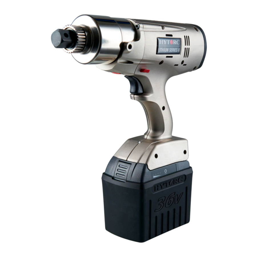
Page 5: Tool Overview
Tool Overview... - Page 6 Tool Overview MODEL Weight (Imperial) Weight (Metric) Torque Range (Imperial) Torque Range (Metric) LST-0700 11.7 lbs 5.3 kg 150-700 ft-lbs 203.4-949.1 Nm LST-1200 12.0 lbs 5.4 kg 200-1200 ft-lbs 271.2-1,627 Nm LST-2000 16.6 lbs 7.5 kg 325-2,000 ft-lbs 440.6-2,711.6 Nm LST-3000 17.7 lbs 8.0 kg...
- Page 7 LITHIUM SERIES Comparison Lithium Series I Lithium Series II Motor Brushless, Longer Life, Quiet Brushed Gearbox Torque Multiplier, 20% Stronger, Nickel Plated Torque Multiplier Housing All Aluminum Plastic with Aluminum Frame Direction Control Switch Via Menu Display High Density LCD, 4X Resolution Standard Density LCD TorcSense™...
- Page 8 L3 Install Reaction Arm (Conventional) L11 Advanced Bolting Features L4 Install Socket (Conventional) L12 Jobs L5 Install HYTORC Washer Driver L13 Profiles L6 Install HYTORC Nut Driver L14 Settings L7 Install Side Handle ...
- Page 9 Inspect Tool and Calibration Check the certificate or label on the tool for the most recent calibration date HYTORC recommends all tools be tested and recalibrated periodically. More frequent calibration may be appropriate depending on local practice, usage and conditions.
- Page 10 General Handling & Usage Environmental Considerations The tool should not be exposed to moisture. Do not operate in rain, snow or extreme humidity. The operating temperature range of the tool is -4°F (–20°C) to 140°F (60°C) Keep cooling vents clear of dust and debris to maintain airflow and keep the motor and electronics within temperature limits.
- Page 11 Test, Charge & Install Battery Insert battery by sliding it onto the charger until it Press TEST button on battery to display remaining charge locks into place. The flashing green indicator light Before charging battery verify local voltage supply to ensure means the battery is charging.
- Page 12 Install Reaction Arm (Conventional Torque) Reaction arm used only for conventional bolting applications. Slide the reaction arm over the drive spline while aligning the Allen Set Screw with the flat on the Reaction Spline. Tighten Allen Set Screw to firmly attach the reaction arm to the spline.
- Page 13 Install Socket (Conventional Torque) Align socket pin hole with hole in the square drive. Make sure the O-ring is installed on the socket – insert the pin part way into the socket. Slide socket on square drive while aligning the pin hole in the socket with the hole in the square drive.
- Page 14 Install HYTORC Washer Driver Slide washer driver over square drive and spline while aligning thumb screw with flat on the spline. Tighten thumb screw to secure Washer Driver. Test to make sure that washer driver is securely...
- Page 15 Install HYTORC Nut Driver Slide nut driver over the square drive and spline while aligning the Allen screw with the flat on the spline. Tighten the Allen screw to secure Nut Driver. Test to make sure that nut driver is securely attached to the spline.
- Page 16 Install Side Handle The side handle screws into the bearing housing on either the right or left side of the tool. Engage threads and rotate clockwise until the handle no longer rotates. Hand tighten only.
- Page 17 Actuate Control Switches Press any button to power on the Tool. Direction Switch Press the Trigger to Activate the Tool. Press the Direction Switch to reverse direction. Slide the Speed Switch to switch from low speed TORQUE to high speed RUN DOWN.
- Page 18 Home Screen/Menu System See LITHIUM SERIES Operations Guide for more detailed instructions regarding menu...
- Page 19 Home Screen/Menu System All bolting functions are configured through a system of menus via the push buttons. Scroll to desired selection and specify desired values using the and buttons. Press the middle button to enter selection. Press to access the Main Menu.
- Page 20 Initialize Basic Bolting Basic bolting options are located at the top of the Main Menu. Specify the desired Torque and Fastener type using the and buttons. Enter values for Angle and Release, if desired. NOTE: For conventional torque the fastener will be Right Hand or Left Hand.
- Page 21 Secure the back nut, if necessary, to prevent from turning during torque operation. For conventional bolting, brace reaction arm firmly against anchor point. Place socket over nut until firmly engaged. If using the HYTORC Washer or HYTORC Nut, make sure the driver properly engages the fastener.
- Page 22 Initialize Basic Bolting Pull and hold the trigger. A message instructs the user to press any button to start, to keep hands clear of reaction arm. Once operator pushes a button the drive will begin to turn. If ANGLE or RELEASE has been specified the tool will pause before finishing each operation.
- Page 23 Advanced Bolting Features Turn Angle: used to complete Turn-Of-Nut procedures by turning a snug-tightened nut through specified angle. Torque Check: used to determine whether a previously tightened nut still meets specification. • Typically, the user sets Torque Check to 90% of the specification value, pulls the trigger and monitors the nut to detect any movement.
- Page 24 Jobs The Jobs function allows the tool to record and document bolting results for a specific operation or sequence. The Job record includes a Job ID, the tool parameters and results for each bolting operation. Start Job: Select a Job ID and begin recording data under that ID. Select End Job to stop recording.
- Page 25 Profiles A Profile is a saved set of tool parameters can be easily recalled from memory. It includes a Profile ID (PID), a Profile Type (PTYPE), and the parameters required for the specific profile type. A profile can be entered directly with the 3-button interface via Create Profile. Enter the Profile ID by scrolling and selecting up to eight characters.
- Page 26 Invert Screen: Flip screen (for when the Tool is inverted). Icons: Turn the menu icons on or off. Auto Shutdown: Enable/disable 5 minutes automatic shutdown. Button Delay: Set button response time. Work Light: Enable/disable the work light. App Mode: Used to sync tool with HYTORC bolting software.
- Page 27 Admin Menu The Admin Menu provides for various administrative functions. NOTE: Not all menu items are available at all access levels. Access Level: Set Tool to one of four password-protected access levels. Tool Info: View Tool information such as firmware version and cycle count. User ID: User can enter their own unique ID for job documentation.
- Page 28 Access Levels The Tool has 5 password-protected Access Levels: L5: Service is reserved for setup and maintenance by HYTORC personnel. L4: Admin provides full access to all functions, settings and menu options. L3: Full User provides access to all standard tool functions and menu items.
- Page 29 Admin Menu L2 Flex Setup The Admin can configure which functions are available to the L2 Flex User. Functions appearing in blue are available by default. Scroll to the function and press the middle button to remove. Functions selected for removal turn black and will not be available at L2 access level. L2 Flex Setup...
- Page 30 Admin Menu Shortcut Setup The Admin can create a customized Shortcut Menu for quick function access. Functions appearing in blue are available by default. Scroll to the function and press the middle button to remove. Functions selected for removal turn black and will not be included in the Shortcut Menu. ...
- Page 31 Admin Menu Change Password The Admin can change the password for any access level on the tool. Passwords can be up to 8 characters long. Allowable characters are 0 to 9, A to Z, and “_”.
- Page 32 Adv Bolting Jobs Settings Admin Service Start Job Units Access Level Calibrate Tool Turn Angle End Job Clock Tool Info Edit Cal Table Torque Check Create Job ID Bluetooth User Id Setup Tool Rotations Import Job IDs Torque Limits L2 Flex Setup Diagnostics Back Export Jobs...
Need help?
Do you have a question about the LITHIUM II Series and is the answer not in the manual?
Questions and answers