Advertisement
Available languages
Available languages
Quick Links
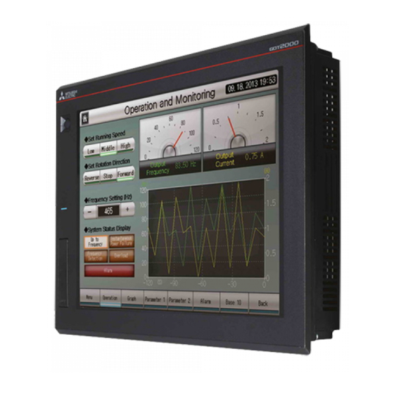
GOT2000 Series Operator
Terminals
Human-Machine Interfaces
Installation Manual for
GT2308-VTBA and GT2308-VTBD
Art. no.: 280289 ENG, Version A, 23092014
Safety Information
For qualified staff only
This manual is only intended for use by properly trained and qualified electri-
cal technicians who are fully acquainted with automation technology safety
standards. All work with the hardware described, including system design,
installation, setup, maintenance, service and testing, may only be performed
by trained electrical technicians with approved qualifications who are fully
acquainted with the applicable automation technology safety standards and
regulations.
Proper use of equipment
The GOT2000 series operator terminals (GT2308) are only intended for the spe-
cific applications explicitly described in this manual or other manuals. Please
take care to observe all the installation and operating parameters specified in
the manual. All products are designed, manufactured, tested and documented
in agreement with the safety regulations. Any modification of the hardware or
software or disregarding of the safety warnings given in this manual or printed
on the product can cause injury to persons or damage to equipment or other
property. Only accessories and peripherals specifically approved by
MITSUBISHI ELECTRIC may be used. Any other use or application of the prod-
ucts is deemed to be improper.
Relevant safety regulations
All safety and accident prevention regulations relevant to your specific appli-
cation must be observed in the system design, installation, setup, mainte-
nance, servicing and testing of these products.
In this manual special warnings that are important for the proper and safe use
of the products are clearly identified as follows:
P
DANGER:
Personnel health and injury warnings.
Failure to observe the precautions described here can result
in serious health and injury hazards.
E
CAUTION:
Equipment and property damage warnings.
Failure to observe the precautions described here can result
in serious damage to the equipment or other property.
Further information
More information about the operator terminals of the GOT2000 series and the
configuration tool MELSOFT GT Works3 is available free of charge through the
internet (https://eu3a.mitsubishielectric.com).
If you have any questions concerning the installation, configuration or opera-
tion of the equipment described in this manual, please contact your relevant
sales office or department.
Dimensions
GT2308
241
All dimensions are in „mm".
Panel cut out
A space of at least 10 mm at
the upper and lower side of
10 or more
the GOT is required to allow for
the attachment of mounting
fixtures.
B
Cut Out [mm]
GOT
A
GT2308
227
10 or more
A
Unit: mm
Distances to other devices
When mounting the GOT, please maintain the following clearances from other
devices.
B
Other device
C
D
E
GOT
A
Panel*
* Panel thickness: 2.0 to 4.0 mm
Minimum clearances [mm]
Distances to other
devices
A
B
C
D
SD card not used
48 (18)
78 (18)
50 (20)
50 (20) 100 (20)
SD card used
48 (18)
78 (18)
50
50 (20) 100 (20)
The values enclosed in parenthesis apply to the case where no other equip-
ment generating radiated noise (such as a contactor) or heat is installed
nearby.
Installation and Wiring
56
P
DANGER
6
● Switch OFF the power supply of the operator terminal before starting
the installation work or wiring and before mounting or removing the
option function board.
● When the communication between the operation terminal and the
PLC fails it is impossible to operate keys or devices via the operation
terminal. Therefore emergency stops and other safety functions must
not be controlled via the PLC.
E
CAUTION
● Do not disassemble or modify the unit. Doing so can cause a failure,
malfunction, injury or fire.
● Use the GOT in the environment that satisfies the general specifica-
tions described in this manual. Don't mount the operation terminal in
an enviroment that contains high explosive risks, strong magnetic
fields, direct sunlight or large, sudden temperature changes.
B
● Never allow fluids, metal filings or wiring debris to enter any openings
+2
+2
176
in the operator terminal. This may cause short circuits and fire.
–0
–0
Mounting
A GOT is designed to be installed into the door of a control cabinet or into
a control panel.
When the temperature inside the control cabinet or
control panel is 40 to 55 °C the mounting angle
105°
should be in the range 60° to 105° degrees.
GOT
60°
Prepare a hole in the panel with the dimensions shown on the left.
Insert the GOT from the front of the
panel or the control cabinet into
the cut out.
E
GOT
Place the mounting fittings (sup-
plied) into the provided openings
of the GOT and tighten the screws
until the GOT is fixed. Please use all
four supplied mounting fittings
and tighten the mounting screws
with a torque of 0.36 to 0.48 Nm.
After mounting, remove the protection film from the operator terminal
display.
Power Supply Wiring
E
CAUTION
● Do not lay signal cables close to the main circuit, high-voltage power
lines, or load lines. Otherwise effects of noise or surge induction are
likely to take place. Keep a safe distance of more than 100 mm from
the above when wiring.
● When connecting the power supply please confirm the rated voltage
and the polarity. Not doing so can cause a fire or failure.
Connect the power supply to the power terminals on the back panel of the GOT.
GT2308-VTBA
INPUT
100-240VAC
(LG) (FG)
Grounding
100 to 240 V AC
Use the thickest cable possible (max. 2 mm
start twisting them close to the connection terminals. Tighten the terminal
screws securely with a torque of 0.5 to 0.8 Nm.
Use commercially available terminal ends for M3 screws for connection of the
power supply (see figure below).
Wiring of one cable to
one terminal
3.2 mm
6.2 mm
or less
3.2 mm
6.2 mm
or less
: Terminal screw
: Solderless terminal
Grounding
Ground the GOT using the ground terminal at the lower left corner of the oper-
ator terminal (Refer to the figure at the top of this column).
● The grounding resistance should be 100
● The grounding point should be close to the GOT. Keep the grounding wires
as short as possible.
Cut out
● The ground wire size should be at least 2 mm
● Independent grounding should be performed for best results. When inde-
pendent grounding is not performed, perform "shared grounding" of the
Magnified illustration
following figure.
Other
GOT
GOT
equipment
Independent grounding
Shared grounding
Mounting
Best condition
Good condition
fitting
Mounting
screw
Connection to the control system
An operator panel of the GOT2000 series can be connected not only to PLCs
from Mitsubishi Electric but also to inverters, servo amplifiers, CNC as well and
to PLCs from third party manufacturers and many other devices. For further
information please refer to the Connection Manual for the GOT2000 series.
Mitsubishi Electric Europe B.V. /// FA - European Business Group ///
Germany /// Tel.: +49(0)2102-4860 /// Fax: +49(0)2102-4861120 ///
https://eu3a.mitsubishielectric.com
GT2308-VTBD
INPUT
24VDC
-
+
(LG) (FG)
Grounding
24 V DC
2
) to minimize the voltage drop and
Wiring of two cables to
one terminal
or less.
2
.
Other
Other
GOT
equipment
equipment
Common grounding
Not allowed
Advertisement

Related Manuals for Mitsubishi Electric GT2308-VTBA


Summary of Contents for Mitsubishi Electric GT2308-VTBA
- Page 1 Only accessories and peripherals specifically approved by or less Insert the GOT from the front of the MITSUBISHI ELECTRIC may be used. Any other use or application of the prod- : Terminal screw panel or the control cabinet into ucts is deemed to be improper.
- Page 2 Frequenzumrichter, Servoverstärker und CNC-Steu- erungen sowie an SPS von Fremdherstellern und vielen anderen Geräten. Wei- tere Informationen enthält die Bedienungsanleitung zur GOT2000-Serie (Anschluss). Mitsubishi Electric Europe B.V. /// FA - European Business Group /// Germany /// Tel.: +49(0)2102-4860 /// Fax: +49(0)2102-4861120 /// https://de3a.mitsubishielectric.com...
- Page 3 à des appareils d’autres fabricants. Pour en savoir plus, voir le Manuel de connexion de la Série GOT2000. Mitsubishi Electric Europe B.V. /// FA - European Business Group /// Germany /// Tel.: +49(0)2102-4860 /// Fax: +49(0)2102-4861120 /// https://eu3a.mitsubishielectric.com...
- Page 4 GT2308-VTBA, GT2308-VTBD GT2308-VTBA GT2308-VTBA, GT2308-VTBD General Specifications Power Supply Specifications Specifications Umgebungsbedingungen Spannungsversorgung Technische Daten Conditions générales de service Alimentation en courant Caractéristiques techniques Item / Merkmal / Description / Beschreibung / Item / Merkmal/ Description / Beschreibung / Item / Merkmal / Description / Beschreibung / Caractéristiques...
- Page 5 Inserire il dispositivo di comando ad es. sportello armadio* : Vite ad anello o capicorda per viti da MITSUBISHI ELECTRIC. Ogni altro utilizzo o applicazione che vada oltre dal lato anteriore del quadro elettri- quanto illustrato è da considerarsi non conforme.
- Page 6 Un terminal de operador de la serie GOT2000 puede conectarse no sólo a PLCs Puede obtenerse gratuitamente vía Internet (https://eu3a.mitsubishielectric.com) de Mitsubishi Electric, sino también a inverters, servoamplificadores, CNCs y a más información acerca de los terminales de operador de la serie GOT2000 PLCs de terceros y a muchos otros dispositivos.
- Page 7 в руководстве по интеграции панелей серии GOT2000. тации панелей оператора, обратитесь в ваше региональное торговое представительство или к вашему региональному торговому партнеру. Mitsubishi Electric Europe B.V. /// FA - European Business Group /// Germany /// Tel.: +49(0)2102-4860 /// Fax: +49(0)2102-4861120 /// https://eu3a.mitsubishielectric.com...
- Page 8 GT2308-VTBA GT2308-VTBA GT2308-VTBA, GT2308-VTBD Condizioni di funzionamento generali Alimentazione Specifiche tecniche Condiciones ambientales Especificaciones de alimentación eléctrica Datos técnicos Окружающая среда Электропитание Технические характеристики Caratteristica / Característica / Descrizione / Descripción / Caratteristica / Característica / Descrizione / Descripción / Caratteristica / Característica /...
- Page 9 Jeśli masz jakiekolwiek pytania związane z instalacją, konfiguracją lub obsługą sprzętu opisanego w tej instrukcji, prosimy o kontakt z właściwym biurem han- dlowym lub oddziałem. Mitsubishi Electric Europe B.V. /// FA - European Business Group /// Germany /// Tel.: +49(0)2102-4860 /// Fax: +49(0)2102-4861120 /// https://eu3a.mitsubishielectric.com...
- Page 10 értékesítési irodával vagy osztállyal. készülékekhez valamint sok más eszközhöz is. További információkat a GOT2000 sorozat készülékeire vonatkozó csatlakoztatási útmutatóban talál. Mitsubishi Electric Europe B.V. /// FA - European Business Group /// Germany /// Tel.: +49(0)2102-4860 /// Fax: +49(0)2102-4861120 /// https://eu3a.mitsubishielectric.com...
- Page 11 Na rozvaděči připravte otvor dle obrázku vlevo. MITSUBISHI ELECTRIC. Jakékoliv jiné použití, které není popsáno v tomto návo- : Šroub svorky du, bude považováno za nesprávné zacházení s tímto zařízením.
- Page 12 GT2308-VTBA, GT2308-VTBD GT2308-VTBA GT2308-VTBA, GT2308-VTBD Ogólne dane techniczne Dane techniczne zasilania Dane techniczne Műszaki jellemzők A tápegység adatai Specifikációk Provozní podmínky Napájecí napětí Technické údaje Pozycja / Tétel / Parametr Opis / Leírás / Popis Pozycja / Tétel / Parametr Opis / Leírás / Popis...
- Page 13 Operatörsnelerna i GT2000-serien kan inte endast anslutas till PLC-enheter från Mer information om operatörsterminaler i GOT2000-serien och konfigure- Mitsubishi Electric, utan också till omvandlare, servoförstärkare, ta bort denna text ringsverktyget MELSOFT GT Works3 kan fås gratis via Internet Efter montering, ta bort skyddsfilmen från opratörsterminalens display.
- Page 14 De grafische bedieningsapparatuur van de GOT2000-serie kan niet alleen wor- de programmeersoftware MELSOFT GT Works3 wordt via het internet ter be- den aangesloten op de PLC’s van Mitsubishi Electric, maar ook op frequentie- schikking gesteld (https://eu3a.mitsubishielectric.com). omvormers, servoversterkers en CNC-besturingen alsmede op PLC’s van derden Mocht u vragen hebben over de installatie, configuratie of bediening van de en vele andere apparaten.
- Page 15 Daha fazla bilgi için, lütfen GOT2000 serisinin Haberleşme Kılavuzuna bakın. Mitsubishi Electric Europe B.V. /// FA - European Business Group /// Germany /// Tel.: +49(0)2102-4860 /// Fax: +49(0)2102-4861120 /// https://eu3a.mitsubishielectric.com...
- Page 16 GT2308-VTBA, GT2308-VTBD GT2308-VTBA GT2308-VTBA, GT2308-VTBD Allmänna specifikationer Specifikation av matningsspänning Teknisk data Omgevingsomstandigheden Spanningsvoorziening Technische gegevens Genel Özellikler Besleme Özellikleri Özellikler Beskrivning / Beschrijving / Beskrivning / Beschrijving / Beskrivning / Beschrijving / Objekt / Kenmerken / Öğe Objekt / Kenmerken / Öğe Objekt / Kenmerken / Öğe...
Need help?
Do you have a question about the GT2308-VTBA and is the answer not in the manual?
Questions and answers