Advertisement
Quick Links
EVBUM2589
)
Bluetooth
Development Kit (B-IDK)
Getting Started Guide
INTRODUCTION
This document helps you get started with the Bluetooth Low Energy
IoT Development Kit (B−IDK). The B−IDK is a comprehensive
node−to−cloud and a modular IoT platform that allows development
of various BLE based use cases. Along with the hardware and
software, the B−IDK includes a mobile app to interact with sensors
and actuators.
The B−IDK features RSL10, Industry's lowest power Bluetooth 5
SoC and comprises of a baseboard (BDK−GEVK) and several sensor
and actuator daughter cards. For a complete listing of available
daughter cards, please visit https://www.onsemi.com/B−IDK. The
daughter cards connect to the baseboard, via the two PMOD
connectors and/or the Arduino connector to enable various use cases.
Scope
This document covers the hardware setup, software architecture,
B−IDK documentation and provides instructions on downloading
firmware to the board. The details regarding the mobile app and cloud
connectivity are not covered in this document.
HARDWARE
•
BDK−GEVK − B−IDK Baseboard
•
Daughter Cards – Optional
•
BDK−DCDC−GEVB – Power Shield For Use With Higher Power
Daughter Cards – Optional
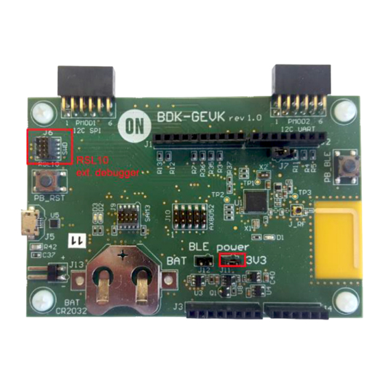
Default Configuration
The BDK−GEVK is shipped with the following jumper
configuration. As the board supports OBD, there is no need for an
external debugger. In case an external debugger is used, connect it to
SWD header, J6.
Powering the Board
Multiple options are available to power the BDK−GEVK.
•
USB
•
Coin Cell (CR2032)
•
External AC/DC Adapter plus power shield (BDK−DCDC−GEVB)
•
External Supply
When higher power daughter cards (listed below) are attached to the
baseboard, external supply either using the power shield or direct is
required.
Higher Power Daughter Cards
•
D−LED−B−GEVK Dual LED Ballast
•
D−STPR−GEVK Dual Stepper Motor Driver
•
BLDC−GEVK BLDC Motor Driver
© Semiconductor Components Industries, LLC, 2015
September, 2019 − Rev. 4
Low Energy IoT
EVAL BOARD USER'S MANUAL
Figure 1. Board Photo
1
www.onsemi.com
Publication Order Number:
EVBUM2589/D
Advertisement

Subscribe to Our Youtube Channel
Related Manuals for ON Semiconductor EVBUM2589


Summary of Contents for ON Semiconductor EVBUM2589
- Page 1 EVBUM2589 Bluetooth Low Energy IoT Development Kit (B-IDK) Getting Started Guide INTRODUCTION This document helps you get started with the Bluetooth Low Energy www.onsemi.com IoT Development Kit (B−IDK). The B−IDK is a comprehensive EVAL BOARD USER’S MANUAL node−to−cloud and a modular IoT platform that allows development of various BLE based use cases.
- Page 2 EVBUM2589 The B−IDK can be powered via the USB port when the use case doesn’t need any higher power daughter cards. An example configuration with the baseboard and a couple of sensor boards is shown below. Coin Cell Once the firmware is flashed onto the baseboard, a coin cell (CR2032) may be used to power the system. Similar to USB based power supply, this method of powering is for use cases that don’t utilize the higher power daughter cards.
- Page 3 (select J−Link software and documentation pack) 3. Download and install“On Semiconductor IDE Installer” from https://www.onsemi.com/PowerSolutions/product.do?id=RSL10 a. Download the RSL10 SDK Getting Started Guide and RSL10 CMSIS pack under “RSL10 Software Package” from the above site. All of these are highlighted in the picture below. Save the CMSIS pack in a folder, for example, C:\cmsis_packs 4.
- Page 4 EVBUM2589 Compiling and Flashing 1. Choose an example (for example, pr_shield_example) to flash by copying it to the workspace. NOTE: Once the example is copied, it can be viewed under Project Explorer. All source files including main are located in the src folder.
- Page 5 EVBUM2589 2. Right click and build the project. This creates binaries to be flashed to BDK−GEVK. NOTE: If the binaries are not seen, press F5 (refresh). 3. Once the build is done, the code is ready to be flashed to the BDK−GEVK. Select the project (pir_shield_example), and go to the debug configurations as shown below.
- Page 6 EVBUM2589 4. Double click GDB Segger J−Link Debugging to create the debug configuration for the selected example. NOTE: The debug configuration for the selected example is automatically saved and there’s no need to re−create it. 5. On the Debugger tab, set RSL10 as the device name. Click Debug to launch the code.
- Page 7 EVBUM2589 Compiling and Flashing 1. Choose an example (for example, pr_shield_example) to flash by copying it to the workspace. NOTE: Once the example is copied, it can be viewed under Project Explorer. All source files including main are located in the src folder.
- Page 8 EVBUM2589 2. Right click and build the project. This creates binaries to be flashed to BDK−GEVK. NOTE: If the binaries are not seen, press F5 (refresh). 3. Once the build is done, the code is ready to be flashed to the BDK−GEVK. Select the project (pir_shield_example), and go to debug configurations as shown below.
- Page 9 EVBUM2589 4. Double click GDB Segger J−Link Debugging to create the debug configuration for the selected example. NOTE: The debug configuration for the selected example is automatically saved and there’s no need to re−create it. 5. On the Debugger tab, set RSL10 as the device name. Click Debug to launch the code.
- Page 10 EVBUM2589 7. The debug session is now launched. Click Resume (F8) to start the target CPU. Logging/Debugging The following options are available to log/debug the downloaded firmware: • Eclipse RTT Console • J−Link RTT • AX8052F100 UART−SPI bridge This section provides instructions for each of the above options.
- Page 11 EVBUM2589 2. Enter the values shown below and launch the session. The incoming events are printed on the terminal window. www.onsemi.com...
- Page 12 EVBUM2589 Using Eclipse Serial Console via UART−SPI Bridge. When you do not want to use the Segger RTT viewer as serial console, the BDK−GEVK board is equipped with UART−SPI uC AX8052F100 flashed with special firmware, taking care of the entire serial communication with values returned on Terminal.
- Page 13 EVBUM2589 NOTE: You may reset (PB_RST) the BDK−GEVK (shown below) to launch the RTT terminal without needing to launch Eclipse. www.onsemi.com...
- Page 14 EVBUM2589 Using J−Link RTT 6. After step 14 is done, open J−Link RTT viewer (should be installed when J−Link software package was installed per Step 2). 7. Select USB and click OK. www.onsemi.com...
- Page 15 EVBUM2589 8. RTT prompts you to select the appropriate microcontroller. Select RSL10 and click OK. The serial terminal is ready to use and the events from RSL10 can be observed by clicking the All Terminals Window. www.onsemi.com...
- Page 16 EVBUM2589 NOTE: You may reset (PB_RST) the BDK−GEVK (shown below) to launch RTT terminal without needing to launch Eclipse. Using Eclipse Serial Console via UART−SPI Bridge The BDK−GEVK board is equipped with UART−SPI microcontroller AX8052F100 flashed with special firmware, to enable serial communication with values returned to Terminal.
- Page 17 EVBUM2589 10. When the project runs, Click the Open a Terminal Icon. 11. Enter the appropriate COM port as shown below and launch the session. The incoming events are printed on the terminal window. www.onsemi.com...
-
Page 18: Software Organization
EVBUM2589 SOFTWARE ORGANIZATION For users modifying the example code and building new projects, the following sections detail the B−IDK software organization. The stack overview is shown below. B−IDK CMSIS Software Organization CMSIS pack and the associated software components handle multiple evaluation boards as different bundles of the standardized Board Support Cclass. - Page 19 EVBUM2589 Board Support • Libraries to support BDK−GEVK, GPIO Expander, Various daughter cards and custom protocol (required for the mobile app) Components • Libraries attached to board support Device • Abstraction layers for interfaces, timers, AES, serial re−direction, etc. •...
-
Page 20: Configuration Setup
EVBUM2589 CONFIGURATION SETUP System settings can be configured directly from within the CMSIS pack. Each example is equipped with basic system configuration that covers three main categories. These are accessible in the RTE/BDK folder within the project. Each system configuration starts with “RTE_”. As shown below, opening the RTE_... header files using the CMSIS configuration wizard (right click on the header file), displays the configuration table. - Page 21 EVBUM2589 RTE_BDK.h Parameters such as system clock frequency and the board that feature RSL10 (default set to BDK−GEVK), etc. can be set. Descriptions of each of these parameters are also provided. RTE_Software_Timer.h Various timers (4) supported by RSL10 can be configured by invoking the CMSIS configuration wizard on this header file.
- Page 22 EVBUM2589 RTE_x.h In addition to configuring system settings, all the supported daughter cards’ parameters can be configured directly using the configuration wizard, without the need for programming. Once the parameters are changed per the application requirements, saving, rebuilding and flashing the project will let the new parameters take effect. Examples for the stepper and LED ballast daughter cards are shown below.
- Page 23 EVBUM2589 DOCUMENTATION Detailed documentation of all functions, code, APIs, HALs is part of the CMSIS package. Every use case (for a particular daughter card, service, etc.) copied into the workspace has its own manual with key description in the abstract.html page. URL Information and orderable part numbers are also provided as shown below.
- Page 24 EVBUM2589 Main Help Page The main help page is accessible via Device/BDK, visible for all use cases in *.rteconfig file. It’s further divided into various modules as shown below. www.onsemi.com...
- Page 25 EVBUM2589 Sub−sections may be expanded for further information (Ex: HAL interfaces shown below) B−IDK also provides software timers and applications task manager abstraction layers to enable management of specific tasks and timing within the event kernel. www.onsemi.com...
- Page 26 EVBUM2589 Custom Service Firmware In order to read sensor data and control actuators connected to the BDK−GEVK from the RSL10 Sense and Control mobile app, the Custom Service Firmware must be downloaded onto the BDK−GEVK. This firmware can be found as Custom Service Firmware under examples in the CMSIS pack.
- Page 27 onsemi, , and other names, marks, and brands are registered and/or common law trademarks of Semiconductor Components Industries, LLC dba “onsemi” or its affiliates and/or subsidiaries in the United States and/or other countries. onsemi owns the rights to a number of patents, trademarks, copyrights, trade secrets, and other intellectual property. A listing of onsemi’s product/patent coverage may be accessed at www.onsemi.com/site/pdf/Patent−Marking.pdf.
- Page 28 Power Management IC Development Tools Click to view products by manufacturer: ON Semiconductor Other Similar products are found below : EVAL-ADM1168LQEBZ EVB-EP5348UI MIC23451-AAAYFL EV MIC5281YMME EV DA9063-EVAL ADP122-3.3-EVALZ ADP130- 0.8-EVALZ ADP130-1.2-EVALZ ADP130-1.5-EVALZ ADP130-1.8-EVALZ ADP1712-3.3-EVALZ ADP1714-3.3-EVALZ ADP1715-3.3- EVALZ ADP1716-2.5-EVALZ ADP1740-1.5-EVALZ ADP1752-1.5-EVALZ ADP1828LC-EVALZ ADP1870-0.3-EVALZ ADP1871-0.6- EVALZ ADP1873-0.6-EVALZ ADP1874-0.3-EVALZ ADP1882-1.0-EVALZ ADP199CB-EVALZ ADP2102-1.25-EVALZ ADP2102-...
Need help?
Do you have a question about the EVBUM2589 and is the answer not in the manual?
Questions and answers