Advertisement
Quick Links
©2019
All Rights Reserved. Reproduction
is prohibited without permission.
Revision date: 09.20.19
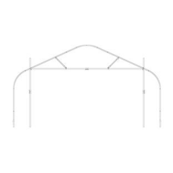
ENDWALL HEADER KIT FOR 20' WIDE GOTHIC PREMIUM
HIGH TUNNEL WITH ROLL-UP ENDS
Some parts shown throughout this guide are included with the main building.
They are not included with this endwall header kit. Rafter is not included.
ATTENTION: HEADER KIT IS NOT FOR
USE WITH ZIPPERED END PANELS.
STK#
116675
for 30' Wide Gothic
Advertisement

Related Manuals for GrowSpan 116675


Summary of Contents for GrowSpan 116675
- Page 1 Some parts shown throughout this guide are included with the main building. ©2019 They are not included with this endwall header kit. Rafter is not included. All Rights Reserved. Reproduction is prohibited without permission. STK# 116675 for 30' Wide Gothic Revision date: 09.20.19...
-
Page 2: Safety Precautions
READ THIS DOCUMENT BEFORE YOU BEGIN Thank you for purchasing this GrowSpan™ Endwall Header Kit. When properly assembled and maintained, this product will provide years of reliable service. These instructions include helpful hints and important information needed to safely assemble and properly maintain the end frame. Please read these instructions before you begin. -
Page 3: Customer-Supplied Materials
(if equipped) when removing snow. Never allow snow to accumulate on the cover or along sides and end panels after removing snow. • Replace all worn or damaged parts promptly. ATTENTION: HEADER KIT IS NOT FOR USE WITH ZIPPERED END PANELS. Revision date: 09.20.19 116675... -
Page 4: Side View
End Rafter Ground Posts 2. After marking hole locations, place a scrap wood block under the tube End Frame Vertical Tubes and drill holes through the tubes using a drill and a 9/16" drill bit. 116675 Revision date: 09.20.19... - Page 5 INTO PLACE WITHOUT SMASHING THE END, THEN TAKE Level ALTERNATIVE STEPS TO SET THE END FRAME VERTICAL COLUMNS. CONTACT A LICENSED CONTRACTOR FAMILIAR WITH SITE LAYOUTS AND SETTING POSTS IN THE AREA. *Actual rafter profile may differ. Frame assembly is the same. Revision date: 09.20.19 116675...
- Page 6 Hand Clamp opening height. Band Band Clamp Clamp Step 15: Secure brackets to frame tube using FA4482B Tek screws. Door Opening Height Mark *Actual rafter profile may differ. Frame assembly is the same. 116675 Revision date: 09.20.19...
- Page 7 18. Take the 5/16" hardware and secure each vertical tube to the end rafter. See Fig. B above and also View 1 of the Connection Details diagram. 19. Continue with the angle brace installation shown in the next section. Revision date: 09.20.19 116675...
- Page 8 6. Return to all band clamps (round and square-tube) and install a Tek screw through each one into either the end rafter pipe or header tube. 7. Continue with the next procedure. ATTENTION: DO NOT INSTALL ANY ROLL-UP DOOR BRACKETS UNTIL YOU INSTALL THE ROLL-UP DOOR PANEL. SEE THE FOLLOWING PROCEDURES FOR ADDITIONAL INFORMATION. 116675 Revision date: 09.20.19...
-
Page 9: Upper Panel
DCC4931—This number identifies the bulk material used to cover the open areas of the end wall and door frame. See diagram on the next page for panel • locations and dimensions. See the panel diagrams in the Quick Start section of the main building guide for additional details before you begin. Revision date: 09.20.19 116675... - Page 10 Cut an 8' x 22' piece of DCC4931 as shown to create an upper panel. Repeat for remaining end wall as needed. Cut an 8' x 11' piece of Cut an 8' x 11' piece of DCC4931 as shown to DCC4931 as shown to create a side panel. create a side panel. 116675 Revision date: 09.20.19...
- Page 11 3. Pull material down to header above door opening, wrap material around header, and attach to backside of header using Tek screws and washers. Do not attach to the front of header tube. This surface is reserved for the installation of the roll-up door panel. 4. Continue with the next procedure. Revision date: 09.20.19 116675...
- Page 12 2" x 2" tube. Secure guide post to the 107923 ROLL-UP DOOR PANEL connectors. See next page. 4. Continue by installing the J-bolts. Step 3 Position Roll-Up Panel Pocket at the bottom during installation.. 116675 Revision date: 09.20.19...
- Page 13 107923 Connectors IMPORTANT: When attaching guide post, turn post as needed so Tek screw at pipe splice will not contact the roll-up panel when it is rolled up or down. Panel conduit and crank handle installed later. Revision date: 09.20.19 116675...
- Page 14 4. Assemble and install the J-bolts. Complete procedure on the next page, then return to these steps. 5. Repeat the steps to install all remaining J-bolts. 6. Continue by installing roll-up panel conduit and spin handle as shown on page 16 of this guide. 116675 Revision date: 09.20.19...
- Page 15 Adjust bolt so J is toward the e. Add the final 3/8" nut to the possible by hand. socket and ratchet. building or end panel side. J-bolt. Return to and continue with Step 5 on the previous page. Revision date: 09.20.19 116675...
- Page 16 (107923) if needed. Do not cut through the end panel. 6. Test the roll-up panel. Space every 48". Tape over screw. 7. Next, attach the end panel material to cover the areas along each side of the installed roll-up panel. See next page. 116675 Revision date: 09.20.19...
- Page 17 Diagram below shows end frame and end rafter as As seen standing outside the building. seen when standing inside the building. Upper Panel FA4482B Tek screws and 102921 neo- bonded washers. Attach panel material to backside of end frame. Revision date: 09.20.19 116675...
- Page 18 Quick Start Section — 116675 ATTENTION: HEADER KIT IS NOT FOR USE WITH ZIPPERED END PANELS. ENDWALL HEADER KIT FOR 30' WIDE GOTHIC PREMIUM HIGH TUNNEL *Some parts shown are included with the main building, not the endwall header kit.
- Page 19 VERTICAL– UPPER Grid squares are 12" x 12" and can be used to set angle brace positions. Dimension is not critical. 105328 2" x 2" x 96" VERTICAL– LOWER GROUND LEVEL 20'- 4" DOOR WIDTH (INSIDE-TO-INSIDE) Revision date: 09.20.19 116675...
- Page 20 VIEW 1 SQUARE TUBE AND ANGLE BRACE VERTICAL TO HORIZONTAL CONNECTION & THROUGH BOLT VIEW 2 CONNECTION TO FRAME VERTICAL & HORIZONTAL 2" X 2" TUBE CONNECTION GROUND LEVEL *Actual frame may differ. Connections are the same. 116675 Revision date: 09.20.19...
- Page 21 BAND CLAMP (106735) ANGLED BRACE 1.66" (AB16G14BEL03025) 2" SQUARE TUBE 5/16"X1-1/2" CARR BOLT (FAH317B) VIEW 4 VIEW 3 BAND CLAMP CONNECTION TO EXISTING FRAME AND ANGLED BRACE BAND CLAMP CONNECTION TO SQUARE TUBE AND ANGLE BRACE Revision date: 09.20.19 116675...
- Page 22 VIEW 5 2"X3" HD 1-WAY CONNECTOR CONNECTION TO VERTICAL SQUARE TUBE VIEW 6 2"X3" HD 1-WAY CONNECTOR CONNECTION TO VERTICAL PIPE VIEW 7 J BOLT CONNECTION GROUND LEVEL *Actual frame may differ. Connections are the same. 116675 Revision date: 09.20.19...
- Page 23 3/8" FLATWASHER (FAME18B) INSIDE OF 2" x 2" TUBE. INSIDE OF 3/8" NUT (FALB14B) 2" x 2" TUBE. 1" HOLE 7/16" 3/8"X5" J BOLT HOLE (FA3629) 3/8" LOCKNUT (FALF19B) 3/8" FLATWASHER (FAME18B) VIEW 7 J BOLT CONNECTION Revision date: 09.20.19 116675...
Need help?
Do you have a question about the 116675 and is the answer not in the manual?
Questions and answers