Panasonic S-M20PY3E Installation Instructions Manual
Hide thumbs
Also See for S-M20PY3E:
- Operating instructions manual (22 pages) ,
- Operating instructions manual (45 pages) ,
- Operating instructions manual (8 pages)
Table of Contents
Advertisement
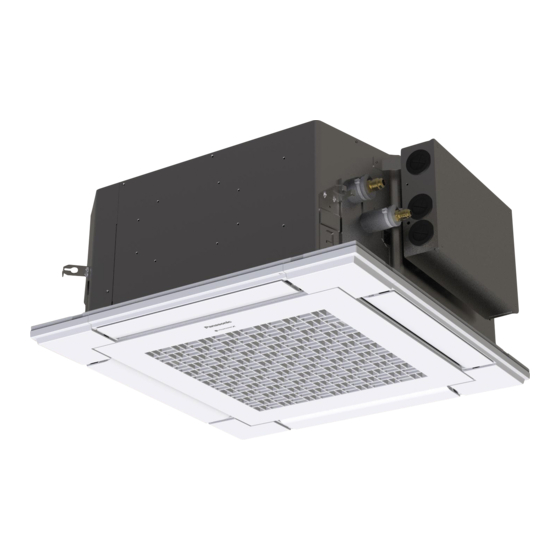
INSTALLATION INSTRUCTIONS
Air Conditioner
This air conditioner uses the refrigerant R32.
Model No.
Indoor Units
Rated Capacity
Type
Indoor Units Type
Y3
4-Way Cassette 60 × 60
* Panel (optional parts)
ENGLISH
Read through the Installation Instructions before you proceed with the installation.
In particular, you will need to read under the "IMPORTANT!" section at the top of the page.
20
25
S-M20PY3E
S-25PY3E
36
50
S-36PY3E
S-50PY3E
(CZ-KPY4)*
60
S-60PY3E
WEB-ACXF60-40970-EN
Advertisement
Table of Contents

Related Manuals for Panasonic S-M20PY3E


Summary of Contents for Panasonic S-M20PY3E
- Page 1 INSTALLATION INSTRUCTIONS Air Conditioner This air conditioner uses the refrigerant R32. Model No. Indoor Units Rated Capacity Type Indoor Units Type S-M20PY3E S-25PY3E S-36PY3E S-50PY3E S-60PY3E 4-Way Cassette 60 × 60 (CZ-KPY4)* * Panel (optional parts) ENGLISH Read through the Installation Instructions before you proceed with the installation.
-
Page 2: Important
• IMPORTANT! Pay close attention to all warning and caution notices given in this manual. Please Read Before Starting This symbol refers to a hazard or WARNING unsafe practice which can result in This air conditioner must be installed by the sales dealer severe personal injury or death. - Page 3 • Check that cabling will not be subject to wear, corrosion, excessive pressure, vibration, sharp edges or any other adverse environmental effects. The check shall also take into account the effects of aging or continual vibration from sources such as compressors or fans. •...
- Page 4 WARNING • When performing piping work, do not mix air except for specified refrigerant in refrigeration cycle. It causes capacity down, and risk of explosion and injury due to high tension inside the refrigerant cycle. • If the refrigerant comes in contact with a flame, it produces toxic gases and fire. •...
- Page 5 WARNING • This product must not be modified or disassembled under any circumstances. Modified or disassembled unit may cause fire, electric shock or injury. • Do not clean inside the indoor and outdoor units by users. Engage authorized dealer or specialist for cleaning. •...
- Page 6 SERVICING CAUTION • Any qualified person who is involved with working on or breaking into a refrigerant circuit should hold a current valid certificate from an industry-accredited assessment authority, which authorizes their competence to handle refrigerants safely in accordance with an industry recognised assessment specification. •...
- Page 7 Marking to the equipment continues to be visible and legible. Markings and signs • that are illegible shall be corrected. Refrigerating pipe or components are installed in a position where they are • unlikely to be exposed to any substance which may corrode refrigerant containing components, unless the components are constructed of materials which are inherently resistant to being corroded or are suitably protected against being so corroded.
- Page 8 REMOVAL AND EVACUATION CAUTION • When breaking into the refrigerant circuit to make repairs – or for any other purpose – conventional procedures shall be used. However, it is important that best practice is followed since flammability is a consideration. The following procedure shall be adhered to: Remove refrigerant.
- Page 9 Recovery equipment and cylinders conform to the appropriate standards. • d) Pump down refrigerant system, if possible. e) If a vacuum is not possible, make a manifold so that refrigerant can be removed from various parts of the system. f) Make sure that cylinder is situated on the scales before recovery takes place. g) Start the recovery machine and operate in accordance with instructions.
-
Page 10: Table Of Contents
CONTENTS Page Page IMPORTANT ......2 7. HOW TO INSTALL THE PANEL FOR CASSETTE ..... 39 Please Read Before Starting 7-1. -
Page 11: Please Read Before Starting
1. GENERAL This booklet briefly outlines where and how to install the air conditioning system. Please read over the entire set of instructions for the indoor and outdoor units and make sure all accessory parts listed are with the system before beginning. The installation of pipe-work shall be kept to a minimum. -
Page 12: Type Of Copper Tube And Insulation Material
Part Name Figure Q’ty Remarks Operating Instructions Installation Instructions As for S-60PY3E, the following accessories are additionally provided. Part Name Figure Q’ty Remarks Gas socket tube A : Different- ø15.88 → ø12.7 diameter-tube Liquid socket tube B : joint ø9.52 → ø6.35 Insulating For gas and liquid tape... -
Page 13: Site
2. SELECTING THE INSTALLATION SITE 2-1. Indoor Unit AVOID: ● areas where leakage of flammable gas may be expected. ● places where large amounts of oil mist exist. ● direct sunlight. ● locations near heat sources which may affect the performance of the unit. ●... -
Page 14: How To Install The Indoor Unit
3. HOW TO INSTALL THE INDOOR UNIT 3-1. Preparation for Suspending This unit uses a drain pump. Use a carpenter’s level to check that the unit is level. 3-2. Suspending the Indoor Unit (1) Fix the suspension bolts securely in the Hole-in-anchor Hole-in-plug Insert... -
Page 15: Placing The Unit Inside The Ceiling
3-3. Placing the Unit Inside the Ceiling This air conditioner is designed to be installed on the system ceiling. Care must be taken before installation so that the maintenance or relocation can be done instantly. This unit is equipped with the drain pump. Check a tape measure or carpenter’s level. Before installing the panel for cassette, complete the work of drain pipe and refrigerant tube installation. -
Page 16: How To Process Tubing
(3) Thread the 3 hexagonal nuts and 2 washers Suspension bolt onto each of the 4 suspension bolts. Use 1 Nuts and washers Suspension lug nut and 1 washer for the upper side, and 2 (use for upper and lower) nuts and 1 washer for the lower side, so that the unit will not fall off the suspension lugs. -
Page 17: Installing The Drain Pipe
3-5. Installing the Drain Pipe 3-5-1. Before Performing the Installation Drain Piping (1) Limitations of Raising the Drain Pipe Connection 300 mm or less CAUTION (as short as possible) ● The drain pipe can be raised to a maximum height of 850 mm from the bottom of the ceiling. A : 850 mm or lower Indoor unit Do not attempt to raise it higher than 850 mm. - Page 18 3-5-2. Installing the Drain Pipe CAUTION ● Do not apply force to the drain port when connecting the drain pipe. Install and fix it near the indoor unit as close as possible. ● Do not use adhesive when connecting the drain port pipe and the drain hose. (1) How to Install the Drain Pipe 1) First insert the supplied hose band into the drain port pipe.
- Page 19 3-5-3. Checking the Drainage Be careful since the fan will start when you short the pin on the indoor CAUTION unit control PCB. After wiring (see Section “4. ELECTRICAL WIRING”.) and drain piping are completed, use the following procedure to check that the water will drain smoothly. For this, prepare a bucket and wiping cloth to catch and wipe up spilled water.
-
Page 20: Important Note For Wiring 4-Way Cassette
3-6. Important Note for Wiring 4-Way Cassette 60 × 60 Type (1) The power supply inlet is located at the lower area of the refrigerant tubing side. The electrical component box is located at the refrigerant tubing side. (2) Before installing the panel for cassette, be sure to carry out the wiring connection. -
Page 21: Electrical Wiring
4. ELECTRICAL WIRING When connecting RAC Multi outdoor unit, see Section “INSTALLATION INSTRUCTION SUPPLEMENT” as well. 4-1. General Precautions on Wiring (1) Before wiring, confirm the rated voltage of the unit as shown on its nameplate, then carry out the wiring closely following the wiring diagram under Section 4-3. WARNING (2) This equipment is strongly recommended to be installed with Earth Leakage Circuit Breaker (ELCB) or Residual Current Device (RCD). -
Page 22: Wire Length And Wire Diameter For Power Supply System
4-2. Wire Length and Wire Diameter for Power Supply System Connection cable between outdoor and indoor unit has 2 types; One is 2-line connection and the other is 3-line connection. Check the type of the outdoor unit terminal board as illustrated below and make connection. - Page 23 Indoor unit (Type of 2-line connection [U1, U2] with indoor and outdoor units) (B) Power supply cable Type Time delay fuse or circuit capacity Min. 2.5 mm Max. 130 m * 15 A Indoor unit (Type of 3-line connection [1, 2 and 3] with indoor and outdoor units) (B) Power supply cable Type Time delay fuse or circuit capacity...
-
Page 24: Wiring System Diagrams
4-3. Wiring System Diagrams ■ 2-LINE CONNECTION Example : Single connection * 3-phase model connections Power supply Power supply 220-230-240V~ 50Hz (Europe) Outdoor unit 380-400-415V 3N~ 50Hz (Europe) 230-240V~ 50Hz (Oceania) Indoor unit (3-phase) 400-415V 3N~ 50Hz (Oceania) Ground Ground Remote controller Integrated control system Power supply... - Page 25 ■ 2-LINE CONNECTION Example : Twin connection * 3-phase model connections Power supply Power supply 220-230-240V~ 50Hz (Europe) Indoor unit Outdoor unit 380-400-415V 3N~ 50Hz (Europe) 230-240V~ 50Hz (Oceania) (No. 1) (3-phase) 400-415V 3N~ 50Hz (Oceania) Ground Ground Remote controller Power supply * Single-phase model connections Indoor unit...
- Page 26 ■ 3-LINE CONNECTION Example : Single connection * Single-phase model connections * Single-phase model connections Outdoor unit Power supply Outdoor unit (single-phase) 220-230-240V~ 50Hz (single-phase) Power supply 220-230-240V~ 50Hz Indoor unit Ground Ground Remote controller Integrated control system * 3-phase model connections Outdoor unit Power supply Indoor unit...
- Page 27 ■ 3-LINE CONNECTION Example : Twin connection * Single-phase model connections Outdoor unit Power supply (single-phase) 220-230-240V~ 50Hz Indoor unit (No. 1) Ground Remote controller Integrated control system * 3-phase model connections Indoor unit Outdoor unit Power supply (No. 2) (3-phase) 380-400-415V 3N~ 50Hz Ground...
- Page 28 ■ 3-LINE CONNECTION Example : Twin connection * Single-phase model connections Outdoor unit Power supply (single-phase) 220-230-240V~ 50Hz Indoor unit (No. 1) Ground Remote controller Integrated control system * 3-phase model connections Power supply Outdoor unit Power supply Indoor unit 220-230-240V~ 50Hz (3-phase) 380-400-415V 3N~ 50Hz...
- Page 29 N OTE 4P terminal board 3P terminal board (1) See Section 4-2 for the explanation of “B”, “C”, “D”, “E”, “F” and “G” under Section 4-3. (2) The basic connection diagram of the indoor unit shows the terminal boards, so the terminal boards in your equipment may differ from the diagram.
- Page 30 (2) Do not install the inter-unit control wiring in a way that forms a loop. Outdoor unit Outdoor unit Outdoor unit Prohibited Prohibited Indoor unit Indoor unit Indoor unit Indoor unit Indoor unit (3) Do not install inter-unit control wiring such as star branch wiring. Star branch wiring causes mis-address setting.
- Page 31 ● In case that the inter-unit control wiring in the link are all 2-line connection only, or mixed with 2-line and 3-line connections: 1) All refrigerant systems are 2-line connection: Outdoor unit : Branch point Central Controller Indoor unit Indoor unit Indoor unit Outdoor unit Indoor unit...
- Page 32 Central Controller Outdoor unit Indoor unit Indoor unit Indoor unit Outdoor unit Indoor unit Indoor unit Indoor unit Outdoor unit : Branch point Indoor unit 3) Only one refrigerant system is 3-line connection and other refrigerant systems are 2-line connection: Central Controller Outdoor unit Indoor unit...
- Page 33 How to connect wiring to the terminal ■ For stranded wiring (1) Cut the wire end with cutting pliers, then Stranded wire strip the insulation to expose the stranded Ring wiring about 10 mm and tightly twist the pressure wire ends. Then attach the ring pressure terminal terminal.
-
Page 34: How To Process Tubing
5. HOW TO PROCESS TUBING When connecting RAC Multi outdoor unit, see Section “INSTALLATION INSTRUCTION SUPPLEMENT” as well. Must ensure mechanical connections be accessible for maintenance purposes. 5-1. Connecting the Refrigerant Tubing Use of the Flaring Method Many of conventional split system air conditioners employ the flaring method to connect refrigerant tubes that run between indoor and outdoor units. -
Page 35: Connecting Tubing Between Indoor And Outdoor Units
5-2. Connecting Tubing Between Indoor and Outdoor Units (1) Tightly connect the indoor-side refrigerant tubing extended from the wall with the outdoor-side tubing. Indoor Unit Tubing Connection Unit : mm Indoor unit type S-25, 36, 50PY3E S-60PY3E Gas tube ø12.7 ø15.88 (ø12.7) Liquid tube ø6.35... - Page 36 Applicable “TWIN”, “TRIPLE” and “DOUBLE TWIN” combination table Outdoor unit Type 71 (Only PZH series) Type 100 Type 125 U-71 U-100 U-125 combination S-36 S-36 S-50 S-50 S-60 S-60 U-100 combination S-36 S-36 S-36 U-125 combination S-36 S-36 S-36 S-36 * Except for the outdoor PZ2 and PZH2 series Outdoor unit Type 140...
-
Page 37: Insulating The Refrigerant Tubing
5-3. Insulating the Refrigerant Tubing Tubing Insulation Must ensure that pipe-work shall be protected from physical damage. ● Thermal insulation must be applied to all units tubing, Two tubes arranged together including distribution joint (field supply). * For gas tubing, the insulation material must be heat Liquid tube Gas tube resistant to 120°C or above. -
Page 38: Taping The Tubes
5-4. Taping the Tubes (1) At this time, the refrigerant tubes (and electrical wiring if local codes permit) should be taped together with armoring tape in 1 bundle. To prevent condensation from overflowing the drain pan, keep the drain hose Clamp separate from the refrigerant tubing. -
Page 39: How To Install The Panel For Cassette
7. HOW TO INSTALL THE PANEL FOR CASSETTE Accessories Panel for cassette ×1 7-1. Preparation for Panel for Cassette Installation (1) Checking the unit position 1) Check that the ceiling hole is within this range: 585 mm × 585 mm to 595 mm × 595 mm 2) Confirm that the position of the indoor unit and the ceiling as shown in the diagram. - Page 40 3) With the air intake grille opened, remove the grille hinge from the panel for cassette by sliding it in the direction shown by the arrow 2. (Reattach the air intake grille after installation of the panel for cassette.) (2) Removing the corner cover Push the latches on the corner cover in the direction of the arrow 1 and remove them by sliding in the direction of the arrow 2.
- Page 41 Refrigerant tube corner Drain tube corner Panel for cassette Marking with REF. PIPE Marking with DRAIN Washer head screws (preinstalled on the panel for cassette) 4) Check that the panel is attached tightly to the ceiling. ● At this time, make sure that there are no gaps Do not allow gaps.
- Page 42 (4) Wiring the Panel for Cassette 1) Open the cover of the electrical component box for the indoor unit control PCB. 2) Connect the 22P connector (black) from the panel for cassette to the connector on the indoor unit control PCB in the unit electrical component box. In this case, expose the cutout section of the tube for the wiring protection to the outside from the electrical component box and fix it with the clamper attached to the electrical component box.
-
Page 43: Others
Drain pipe side Optional wireless receiver kit * This position is only possible for installation. Corner cover installation position marked with the Panasonic Logo at shipment. * Installation possible at any of 4 corners Can be installed rotated 90° Locations of air intake grille hinges at shipment * The grille can be installed with these hinges facing in any of 4 directions. - Page 44 <Procedure of CZ-RTC5B> Refer to Section “Flap Setting for Each Air Outlet” in the Operating Instructions attached to the optional High-spec Wired Remote Controller. <Procedure of CZ-RTC4> Stop the system before performing these steps. ° YYYY 1 Press and hold the buttons °...
- Page 45 <Procedure of CZ-RTC6 series> Stop the system before performing these steps. 1 Keep pressing the buttons simultaneously for 4 or more seconds. The “Maintenance func” screen appears on the LCD display. Maintenance func XX / XX ECONAVI nanoeX RC. setting mode Maintenance func 2 Press the button to see each menu.
-
Page 46: How To Install Wireless Remote Controller
Change the value by pressing the button. Code no. 000001 - XXXXXX After changing all digits, press the button and proceed to 0 0 0 Step 5. Set data 0001 0001 Fig. C Code no. 5 Select one of the Setting Data “YYYY” by pressing the 000001 - XXXXXX button. -
Page 47: Test Run
9. TEST RUN When connecting RAC Multi outdoor unit, see Section “INSTALLATION INSTRUCTION SUPPLEMENT” as well. 9-1. Precautions ● Request that the customer be present when the test run is performed. At this time, explain the operation manual and have the customer perform the actual steps. ●... - Page 48 Group control address 0099 List of detailed setting items code nos. 11, 12, 13, 14 Set data Code no. Item Description Description 0001 S-M20PY3E (20) Y3 0003 S-25PY3E (25) Y3 Indoor unit 0005 S-36PY3E (36) Y3 0009 S-50PY3E (50) Y3 capacity...
- Page 49 N OTE The Item code numbers 11, 12, 13 and 14 can automatically be changed to the appropriate settings from factory settings listed above by making the auto address settings according to the connected outdoor unit capacity and the number of indoor units. If needed to reset the settings after once changed, return all the item codes to the factory shipment-time settings.
- Page 50 (5) Select the “Set data” by pressing the button. Detailed settings 20:30 (THU) Select one of the Setting Data “YYYY” by pressing the Unit no. Code no. Set data button. YYYY Then press the button. Sel. ] Confirm If you wish to change the selected indoor unit, follow Step (3). (6) Press the button to finish.
- Page 51 <Procedure of CZ-RTC6 series> Stop the system before performing these steps. (1) Keep pressing the buttons simultaneously for 4 or more seconds. The “Maintenance func” screen appears on the LCD display. Maintenance func XX / XX ECONAVI nanoeX RC. setting mode Maintenance func (2) Press the button to see each menu.
- Page 52 Change the value by pressing the button. Code no. 000001 - XXXXXX After changing all digits, press the button and proceed to 0 0 0 Step (5). Set data 0001 0001 Fig. C (5) Select one of the Setting Data “YYYY” by pressing the Code no.
- Page 53 9-4. Check the Combination (wiring) of Indoor and Outdoor Units Connection cable between outdoor and indoor unit has 2 types; One is 2-line connection and the other is 3-line connection. Check the type of the outdoor unit terminal board as illustrated below and make connection.
- Page 54 9-5-2. Basic connection 2 : Group control operation (when not using integrated control system) ● Before turning on the power (earth leakage circuit breaker), make refrigerant system auto address setting. (See Section 9-5-5.) ● Turn on the system 1 indoor and outdoor units (earth leakage circuit breaker) and make indoor unit auto address setting.
- Page 55 9-5-3. Basic connection 3 : Example of link wiring (when using integrated control system) ● Before turning on the power (earth leakage circuit breaker), set the system address of each outdoor unit with the rotary switch. ● Turn on the power supply (earth leakage circuit breaker) of each system, make each system auto address setting by using the remote controller or short-circuiting the auto address pin of outdoor unit.
- Page 56 9-5-5. Setting the Outdoor unit system addresses For basic wiring diagram (Set the system address: 1) Outdoor unit control PCB System address rotary switch (Set to “0” at time of shipment) System address System address System address rotary switch System address No. 10 digit 1 place (2P DIP switch)
- Page 57 9-6-2. Basic connection 2 : Group control operation (when not using integrated control system) ● Turn on the system 1 indoor and outdoor units (earth leakage circuit breaker) and make indoor unit auto address setting. (See Section 9-7.) Two group control Refrigerant system 1 Refrigerant system 2 Do not turn on the system 2...
- Page 58 9-6-3. Basic connection 3 : Example of link wiring (when using integrated control system) ● Turn on the power of each system, specify a different system address for each system and make auto address setting from each remote controller. (See Section 9-7.) Refrigerant system 1 Refrigerant system 2 Refrigerant system 3...
-
Page 59: Auto Address Setting Using The Remote Controller
9-7. Auto Address Setting Using the Remote Controller Auto Address Setting from the High-spec Wired Remote Controller (CZ-RTC5B) 20:30 (THU) (1) Keep pressing the buttons simultaneously for 4 or more seconds. START The “Maintenance func” screen appears on the LCD display. - Page 60 Auto Address Setting* from the Remote Controller (CZ-RTC4) N OTE ● Selecting each refrigerant system individually for auto address setting ● Auto address setting for each system : Item code “A1” (1) Press the remote controller timer time button and button at the same time.
- Page 61 Auto Address Setting from the Wired Remote Controller (CZ-RTC6 series) (1) Keep pressing the buttons simultaneously for 4 or more seconds. The “Maintenance func” screen appears on the LCD display. Maintenance func XX / XX ECONAVI nanoeX RC. setting mode (2) Press the button to see each menu.
-
Page 62: How To Set Refrigerant System Address (Only Outdoor Pz2 And Pzh2 Series)
9-8. How to Set Refrigerant System Address (Only outdoor PZ2 and PZH2 series) ● Turn on the power in the indoor and outdoor units of the refrigerant system 1. ● Switch the power on and wait at least 1 minute and 30 seconds or more. Short-circuit the auto address pin of the outdoor unit with turned on and release. - Page 63 CZ-RTC4 (Timer remote controller) <If 1 indoor unit is connected to 1 remote controller> Number changes to indicate which (1) Press and hold the button and button for 4 indoor unit is currently selected. seconds or longer (simple settings mode). Indoor unit address (2) The address is displayed for the indoor unit that is connected to the remote controller.
- Page 64 CZ-RTC6 series (Wired Remote Controller) (1) Keep pressing the buttons simultaneously for 4 or more seconds. The “Maintenance func” screen appears on the LCD display. Maintenance func XX / XX ECONAVI nanoeX RC. setting mode (2) Press the button to see each menu. Maintenance func XX / XX Select “Simple settings”...
-
Page 65: Test Run Using The Remote Controller
9-10. Test Run Using the Remote Controller CZ-RTC5B (High-spec wired remote controller) This mode places a heavy load on the machines. Therefore 20:30 (THU) use it only when performing the test run. (1) Keep pressing the buttons simultaneously for 4 or more seconds. START The “Maintenance func”... - Page 66 CZ-RTC4 (Timer remote controller) This mode places a heavy load on the machines. Therefore use it only when performing the test run. (1) Press the remote controller button for 4 seconds or longer. Then press the button. “ ” appears on the LCD display while the test run is in progress.
- Page 67 CZ-RTC6 series (Wired Remote Controller) This mode places a heavy load on the machines. Therefore use it only when performing the test run. (1) Keep pressing the buttons simultaneously for 4 or more seconds. The “Maintenance func” screen appears on the LCD display.
-
Page 68: Main-Sub Remote Controller Control
9-11. Main-Sub Remote Controller Control One (1) indoor unit can be controlled by two (2) wired remote controllers. In the case of using 2 remote controllers, one of them needs to be designated as the sub remote controller. Connecting 2 remote controllers to control 1 indoor unit Remote controller Remote controller (main) - Page 69 Remote controller setting mode (CZ-RTC6 series) (1) Press and hold the for 4 seconds or more simultaneously. (2) Select “RC. setting mode”. Maintenance func XX / XX → ECONAVI nanoeX RC. setting mode (3) Select the “Code no.” and “ Set data”. RC.
-
Page 70: Checklist After Installation Work
10. CHECKLIST AFTER INSTALLATION WORK □ Work List Content Check Possibility of Failure & Checkpoint Are the indoor units installed following the □ There is a possibility of light injure or loss of Installation content of Section “2. SELECTING THE property. -
Page 71: Appendix
11. APPENDIX ■ Care and Cleaning WARNING ● For safety, be sure to turn the air conditioner off and also to disconnect the power before cleaning. ● Do not pour water on the indoor unit to clean it. This will damage the internal components and cause an electric shock hazard. - Page 72 N OT E The frequency with which the filter should be cleaned depends on the environment in which the unit is used. Clean the filter frequently for best performance in the area of dusty or oil spots regardless of filter status.
-
Page 73: Troubleshooting
Care: After a prolonged idle period Check the indoor and outdoor unit air intakes and outlets for blockage; if there is a blockage, remove it. Care: Before a prolonged idle period ● Operate the fan for half a day to dry out the inside. ●... -
Page 74: Tips For Energy Saving
● Check Before Requiring Services Symptom Cause Remedy Air conditioner does not run Power failure or after power failure Press ON/OFF operation button on remote at all although power is turned controller again. Operation button is turned off. ● Switch on power if breaker is turned off. ●... -
Page 75: Check Of Density Limit
12. CHECK OF DENSITY LIMIT The refrigerant (R32), which is used in the air conditioner, is a flammable refrigerant. So the requirements for installation space in each room of appliance are determined according to the refrigerant charge amount [m ] used in the appliance. Regarding the refrigerant charge amount [m ] used in the appliance, refer to the installation instructions for the outdoor unit. -
Page 76: Supplement
SUPPLEMENT Contents of Remote Controller Switch Alarm Display Blinking: OFF: Wireless remote controller receiver display Abnormal Alarm contents Error location display Faulty remote controller • Replace the remote controller Disconnection / Contact failure of remote controller wiring • Correct the remote controller wiring CHK (check) pins on the indoor unit control PCB are short •... - Page 77 Blinking: OFF: Wireless remote controller receiver display Abnormal Alarm contents Error location display Indoor unit fan motor locked • Remove the cause Indoor unit fan motor layer short • Replace the fan motor Contact failure in thermostat protector circuit • Correct the wiring •...
- Page 78 Blinking: OFF: Wireless remote controller receiver display Abnormal Alarm contents Error location display Duplication of outdoor unit address • Check the indoor / outdoor control line * • Replace the outdoor unit EEPROM Outdoor unit capacity is not set or setting error Operating •...
-
Page 79: Installation Instruction Supplement
INSTALLATION INSTRUCTION SUPPLEMENT The outdoor unit to be connected is CU-2Z35/2Z41/2Z50/3Z52/3Z68/4Z68/4Z80/5Z90***. Check this manual for the following contents before performing the installation work. 4. ELECTRICAL WIRING 5. HOW TO PROCESS TUBING 9. TEST RUN 4. ELECTRICAL WIRING 4-1. General Precautions on Wiring (1) Before wiring, confirm the rated voltage of the unit as shown on its nameplate, then carry out the wiring closely following the wiring diagram under Section 4-4. - Page 80 4-2. Recommended Wire Length and Wire Diameter for Power Supply System The terminal block of the outdoor unit is as shown in the figure below. Wire the indoor units one by one to the terminal blocks of unit A to unit E. (Example of CU-5Z90*** outdoor unit) UNIT UNIT...
- Page 81 4-3. Wiring System Diagram Outdoor unit Power supply ■ Wiring System Diagram For RAC Multi (single-phase) 230V ~ 50Hz Indoor unit Ground (UNIT A) (UNIT B) Remote controller Indoor unit (UNIT E) Remote controller Indoor unit Remarks : Remote controller RAC Multi Outdoor Terminal Indication Multi 2 (UNIT A)
- Page 82 NOT E (1) See Section 4-2 for the explanation of “D”, 4P terminal board 3P terminal board and “G” under Section 4-3. (2) The basic connection diagram of the indoor unit shows the terminal boards, so the terminal boards in your equipment may differ from the diagram.
- Page 83 5. HOW TO PROCESS TUBING Must ensure mechanical connections be accessible for maintenance purposes. 5-1. Connecting the Refrigerant Tubing Use of the Flaring Method Many of conventional split system air conditioners employ the flaring method to connect refrigerant tubes that run between indoor and outdoor units. In this method, the copper tubes are flared at each end and connected with flare nuts.
- Page 84 Use Pipe size Reducer (CZ-MA1PA) is separate purchase Different-diameter-tube joint for the indoor unit tubing S-60PY3E connection part is supplied with S-60PY3E. Liquid and Gas side piping connection diagram. Indoor Model Multi R32 Model Pipe connection diagram S-M20PY3E CU-2Z35*** S-25PY3E CU-2Z41*** S-36PY3E CU-2Z50*** CU-3Z52*** Liquid tube (ø6.35) CU-3Z68*** Gas tube (ø9.52)
- Page 85 (2) To fasten the flare nuts, apply specified torque. ● When removing the flare nuts from the tubing connections, or when tightening them after connecting the tubing, be sure to use two spanners. When tightening the flare nuts, use a torque wrench. If the flare nuts are over-tightened, the flare may be damaged, which could result in refrigerant leakage and cause injury or asphyxiation to room occupants.
- Page 86 5-3. Insulating the Refrigerant Tubing Tubing Insulation Must ensure that pipe-work shall be protected from physical damage. ● Thermal insulation must be applied to all units tubing, Two tubes arranged together including distribution joint (field supply). * For gas tubing, the insulation material must be heat Liquid tube Gas tube resistant to 120°C or above.
- Page 87 9. TEST RUN WHEN CONNECT TO RAC MULTI OUTDOOR 9-1. Precautions ● Request that the customer be present when the test run is performed. At this time, explain the operation manual and have the customer perform the actual steps. ● Check that the 230 VAC power is not connected to the inter-unit control wiring connector terminal.
- Page 88 9-6’ Address Setting : 3-Line Connection TEST RUN : Address Setting NOT E The displays of the earth, outdoor unit power supply wiring and earth leakage circuit breaker are omitted. ■ 3-LINE CONNECTION ● RAC Multi operations : It is possible to operate maximum 5 indoor units within one outdoor unit.
- Page 89 WEB-ACXF60-40970-EN DC0821-0...
Need help?
Do you have a question about the S-M20PY3E and is the answer not in the manual?
Questions and answers