Table of Contents
Advertisement
Quick Links
INSTALLATION INSTRUCTIONS
Air Conditioner
This air conditioner uses the refrigerant R410A.
Model No.
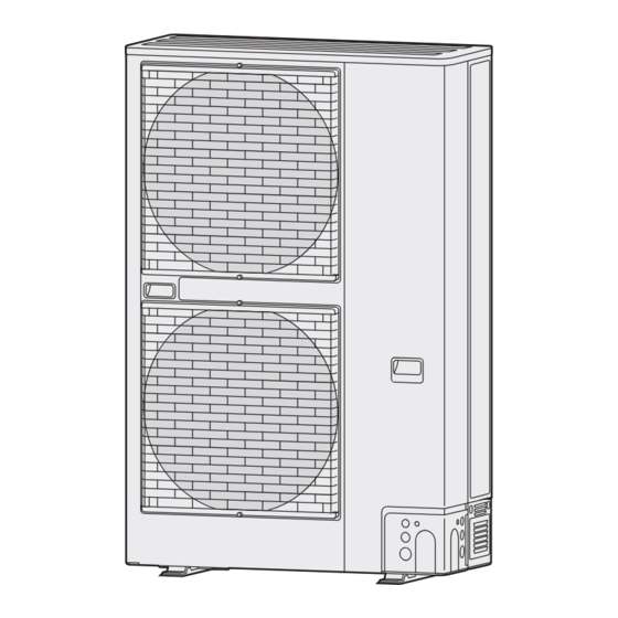
Outdoor Units
Type Outdoor Unit Type
LE1 mini VRF System
High-Durable model
*
• To be connecting Indoor Unit
Indoor Units
Type
Indoor Unit Type
D1
1-Way Cassette
L1
2-Way Cassette
U1
4-Way Cassette
Y2
4-Way Cassette 60 × 60
K1
Wall-Mounted
K2
Wall-Mounted
T2
Ceiling
F2
Low Silhouette Ducted
M1 Slim Low Static Ducted
P1
Floor Standing
R1
Concealed Floor Standing
Z1
Slim Type Ducted
Type
Indoor Unit Type
D1
1-Way Cassette
L1
2-Way Cassette
U1
4-Way Cassette
K1
Wall-Mounted
T2
Ceiling
F2
Low Silhouette Ducted
E1
High Static Pressure Ducted
P1
Floor Standing
R1
Concealed Floor Standing
Z1
Slim Type Ducted
Type
Indoor Unit Type
E1
High Static Pressure Ducted
E2
High Static Pressure Ducted
Read through the Installation Instructions before you proceed with the installation. In particular, you will need to read under
the " IMPORTANT ! " section at the top of the page.
HP = horsepower
Rated Capacity
8 HP
10 HP
U-8LE1R8
U-10LE1R8
U-8LE1R8E* U-10LE1R8E*
22
S-28MD1E5
S-22ML1E5
S-28ML1E5
S-22MU1E5A S-28MU1E5A S-36MU1E5A S-45MU1E5A S-56MU1E5A S-60MU1E5A
S-22MY2E5A S-28MY2E5A S-36MY2E5A S-45MY2E5A S-56MY2E5A
S-22MK2E5A S-28MK2E5A S-36MK2E5A
S-22MF2E5A S-28MF2E5A S-36MF2E5A S-45MF2E5A S-56MF2E5A S-60MF2E5A
S-22MM1E5A S-28MM1E5A S-36MM1E5A S-45MM1E5A S-56MM1E5A
S-22MP1E5
S-28MP1E5
S-22MR1E5
S-28MR1E5
S-22MZ1H4A S-28MZ1H4A S-36MZ1H4A S-45MZ1H4A S-56MZ1H4A S-60MZ1H4A
71 / 73
S-73MD1E5
S-73ML1E5
S-73MU1E5A S-90MU1E5A S-106MU1E5A S-140MU1E5A S-160MU1E5A
S-73MK1E5A
S-73MT2E5A
S-73MF2E5A S-90MF2E5A S-106MF2E5A S-140MF2E5A S-160MF2E5A
S-73ME1E5
S-71MP1E5
S-71MR1E5
S-73MZ1H4A
Rated Capacity
180
S-224ME1E5 S-280ME1E5
S-180ME2E5
S-224ME2E5 S-280ME2E5
Rated Capacity
28
36
S-36MD1E5
S-45MD1E5
S-36ML1E5
S-45ML1E5
S-45MK1E5A S-56MK1E5A
S-36MT2E5A S-45MT2E5A S-56MT2E5A
S-36MP1E5
S-45MP1E5
S-36MR1E5
S-45MR1E5
Rated Capacity
90
106
S-106MK1E5A
S-106MT2E5A S-140MT2E5A
S-106ME1E5 S-140ME1E5
224
280
45
56
S-56MD1E5
S-56ML1E5
S-56MP1E5
S-56MR1E5
140
160
60
ACXF60-02770
Advertisement
Table of Contents

Related Manuals for Panasonic U-8LE1R8


Summary of Contents for Panasonic U-8LE1R8
- Page 1 This air conditioner uses the refrigerant R410A. Model No. Outdoor Units HP = horsepower Rated Capacity Type Outdoor Unit Type 8 HP 10 HP U-8LE1R8 U-10LE1R8 LE1 mini VRF System U-8LE1R8E* U-10LE1R8E* High-Durable model • To be connecting Indoor Unit Indoor Units Rated Capacity...
-
Page 2: Important
IMPORTANT! SPECIAL PRECAUTIONS Please Read Before Starting WARNING When Wiring This air conditioner must be installed by the sales dealer or installer. This information is provided for use only by authorized ELECTRICAL SHOCK CAN persons. CAUSE SEVERE PERSONAL For safe installation and trouble-free operation, you INJURY OR DEATH. - Page 3 When Transporting When Connecting Refrigerant Tubing • It may need two or more people to carry out the installation work. Pay particular attention to refrigerant leakages. • Be careful when picking up and moving the indoor and outdoor units. Get a partner to help, and bend your knees WARNING when lifting to reduce strain on your...
- Page 4 When Servicing Others • Turn the power OFF at the main CAUTION power box (mains), wait at least 10 minutes until it is discharged, then • Do not touch the air inlet or open the unit to check or repair the sharp aluminum fins of the electrical parts and wiring.
- Page 5 Check of Density Limit (3) If an indoor unit is installed in each partitioned room and the refrigerant tubing is interconnected, the smallest room Check the amount of refrigerant in the system and of course becomes the object. But when mechanical floor space of the room according to the legislation on ventilation is installed interlocked with a gas leakage refrigerant drainage.
- Page 6 Precautions for Installation Using New Refrigerant 1. Care regarding tubing 1-1. Process tubing ● Material: Use seamless phosphorous deoxidized copper tube for refrigeration. Wall thickness shall comply with the applicable legislation. The minimal wall thickness must be in accordance with the table below. For tubes of ø22.22 or larger, use the material of temper 1/2H or H (Hard copper tube).
- Page 7 Important Information Regarding The Refrigerant Used This product contains fluorinated greenhouse gases covered by the Kyoto Protocol. Do not vent gases into the atmosphere. Refrigerant type: R410A value: 1975 GWP = global warming potential Periodical inspections for refrigerant leaks may be required depending on European or local legislation. Please contact your local dealer for more information.
-
Page 8: Table Of Contents
CONTENTS Page Page IMPORTANT! ........2 6. -
Page 9: General
1. GENERAL This booklet briefly outlines where and how to install the air conditioning system. Please read over the entire set of instructions for the outdoor unit and make sure all accessory parts listed are with the system before beginning. For the renewal installation, refer to the Technical Data. -
Page 10: Tubing Length
1-5. Tubing Length Select the installation location so that the length and size of refrigerant tubing are within the allowable range shown in the figure below. Main tubing length (maximum tubing size) LM = LA + LB … Main distribution tubes LC – LH are selected according to the capacity after the distribution joint. Sizes of indoor unit connection tubing 1 –... -
Page 11: Tubing Size
Table 2-2 : Values of indoor unit Rated Capacity Type 71/73 – 0.117 – 0.145 – – – – – – – 0.129 – 0.193 – – – – – – – 0.175 0.197 0.263 – – – 0.130 0.134 –... -
Page 12: Straight Equivalent Length Of Joints
1-7. Straight Equivalent Length of Joints Design the tubing system by referring to the following table for the straight equivalent length of joints. Table 6 : Straight Equivalent Length of Joints Gas tubing size (mm) 12.7 15.88 19.05 22.22 25.4 90°... -
Page 13: System Limitations
1-9. System Limitations Table 10 : System Limitations Outdoor unit horsepower 8 HP 10 HP Number of max. connectable indoor units Max. allowable indoor/outdoor capacity ratio 50-130% * In case that the total value of connected indoor units exceeds 1.200, increase the size of the main tube (LM) by 1 rank for liquid tube. -
Page 14: Installing Distribution Joint
1-11. Installing Distribution Joint (1) Refer to “HOW TO ATTACH DISTRIBUTION JOINT” enclosed with the optional distribution joint kit (CZ-P160BK2, CZ-P680BK2). ● When connecting a branch tubing to the indoor unit directly, it is necessary for each branch tubing to install at a positive angle with respect to horizontal in order to prevent accumulation of refrigerant oil in stopped units. -
Page 15: Optional Distribution Joint Kits
1-12. Optional Distribution Joint Kits See the installation instructions packaged with the distribution joint kit for the installation procedure. Table 11 Cooling capacity Model name Remarks after distribution 1. CZ-P160BK2 22.4 kW or less * For indoor unit 2. CZ-P680BK2 more than 22.4 kW * For indoor unit * In case the total capacity of indoor units connected after distribution exceeds the capacity of the outdoor unit, select the distribution... -
Page 16: Example Of Tubing Size Selection And Refrigerant
1-13. Example of Tubing Size Selection and Refrigerant Charge Amount Additional refrigerant charging Based on the values in Tables 3, 4, 5 and 8, use the liquid tubing size and length, and calculate the amount of additional refrigerant charge using the formula below. Required additional =[128 ×(a) + 56 ×(b) + 26 ×(c)] ×10 + Necessary amount of additional refrigerant charge per... - Page 17 Example: Checking of limit density Density limit is determined on the basis of the size of a room using an indoor unit of minimum capacity. For instance, 8 HP when an indoor unit is used in a room (floor area 8.00 m ×...
-
Page 18: Selecting The Installation Site
2. SELECTING THE INSTALLATION SITE (2) Obstructions on the left side, right side and rear side (Front side and above the unit are opened). 2-1. Outdoor Unit AVOID: ● heat sources, exhaust fans, etc. Exhaust fan Hot air 150 mm 250 mm or more or more... - Page 19 (6) Obstructions on the left side, right side and rear side (Front side and above the unit are opened). * The outdoor units require necessary space to unscrew on the rear side for maintenance and if a sufficient maintenance space is provided on the rear side (400 mm), the space of 150 mm 250 mm 250 mm...
-
Page 20: Air-Discharge Chamber For Top Discharge
2-2. Air-Discharge Chamber for Top Discharge 2-4. Precautions for Installation in Heavy Snow Areas Be sure to install an air-discharge chamber in the field when: (1) The platform should be higher than the max. snow depth. ● it is difficult to keep a sufficient space between the air discharge outlet and an obstacle. -
Page 21: Dimensions Of Air-Discharge Chamber
2-5. Dimensions of Air-Discharge Chamber Reference diagram for air-discharge chamber (field supply) Unit: mm Air intake Air intake 4-ø13 Anchor bolt hole Air discharge (163) (116) 43.5 (324.5) Air discharge Air intake Air intake Air discharge... -
Page 22: Dimensions Of Snow-Proof Vents
2-6. Dimensions of Snow-Proof Vents Reference diagram for snow-proof vents (field supply) Unit: mm (32.5) 233.5 Air intake Air intake 4-ø13 Anchor bolt hole Air discharge 1284 (29.5) 310.5 (13.5) 306.5 Air discharge Air intake Air intake Air discharge Required space around outdoor unit when using snow-proof vents [Obstacle to the rear of unit] ●... -
Page 23: How To Install The Outdoor Unit
3. HOW TO INSTALL THE OUTDOOR UNIT 3-2. Drainage Work Follow the procedure below to ensure adequate draining for the outdoor unit. 3-1. Installing the Outdoor Unit For the drain port dimensions, see Fig. 3-1. ● Use concrete or a similar material to create the base, and ●... -
Page 24: Electrical Wiring
4. ELECTRICAL WIRING 4-1. General Precautions on Wiring (1) Before wiring, confirm the rated voltage of the unit as shown on its nameplate, then carry out the wiring closely following the wiring diagram. (2) Provide a power outlet to be used exclusively for each unit, and a power supply disconnect, circuit breaker and earth leakage breaker for overcurrent protection should be provided in the exclusive line. -
Page 25: Recommended Wire Length And Wire Diameter For Power Supply System
4-2. Recommended Wire Length and Wire Diameter for Power Supply System Outdoor unit (A) Power supply (A) Power supply Time delay fuse or Time delay fuse or circuit capacity circuit capacity Wire size Max. length Wire size Max. length 6 mm² 86 m 25 A 8 HP... -
Page 26: Wiring System Diagram
4-3. Wiring System Diagram Indoor unit (No. 1) Power supply Outdoor unit 220/230/240V ~ 50/60 Hz INV unit Ground Power supply Remote 400/415V, 3 N~, 50Hz controller Ground Ground Indoor unit (No. 2) Power supply Ground 220/230/240V ~ 50/60 Hz Ground Remote controller... - Page 27 CAUTION (1) When linking outdoor units in a network, see the section “ATTENTION!”. (2) Do not install the inter-unit control wiring in a way that forms a loop. Outdoor unit Outdoor unit Outdoor unit Prohibited Prohibited Indoor unit Indoor unit Indoor unit Indoor unit Indoor unit...
- Page 28 (5) Use shielded wires for inter-unit control wiring (C) Shielded wire and ground the shield on both sides, otherwise misoperation from noise may occur. Connect wiring as shown in the section “4-3. Wiring System Diagram.” Ground Ground (6) • Connecting cable between indoor unit and outdoor unit shall be approved polychloroprene sheathed 5 or 3 *1.5 mm flexible cord.
- Page 29 ■ Wiring sample Use this screw when connecting to ground for the inter-unit control wiring. Earth Inter-unit control wiring Power supply Torque value of power supply terminal board: 2.0 N·m ± 0.05 N·m {20 kgf·cm ± 0.5 kgf·cm} Torque value of communication terminal board: 1.3 N·m ± 0.1 N·m {13 kgf·cm ± 1 kgf·cm} ATTENTION: Comply with the torque values.
- Page 30 Connection for demand and forced stop ■ Connection procedure Be sure to always turn the power off first when setting up the wire and cable connections. Failure to do so may lead to electric shock or unit failure. Forced Stop connection for the next system The next system Outdoor unit...
- Page 31 When connecting the demand controller input Termrial no. for Description demand section It is possible to choose various demand levels. See the table shown on the right. DRM3 Approx. 75% of rated power input DRM2 Approx. 50% of rated power input DRM1 Compressor off Connect the wiring (4-wire) to the Demand section (DRM1,...
- Page 32 When connecting to the next system unit Forced Stop input can be transferred to the next system unit. ● When using the Forced Stop input, connect the wiring to the terminal points 1 and 2 on the right side of the lower part of the terminal ●...
- Page 33 ■ Wiring procedure Follow the wiring procedure below for terminal connection. (1) Set the wiring and cables for the power and signal lines to the outdoor unit together, and secure each wire and cable with the tie. (2) Secure and clamp the power and signal lines with the tie, set up close to the valve. (3) Set up the wiring and cable for the outdoor unit piping and secure with a tie.
-
Page 34: How To Process Tubing
Caution Before Connecting Tubes Tightly 5. HOW TO PROCESS TUBING The liquid tubing side is connected by a flare nut, and the gas (1) Apply a sealing cap or water-proof tape to prevent dust or tubing side is connected by brazing. water from entering the tubes before they are used. -
Page 35: Connecting Tubing Between Indoor And Outdoor Units
5-2. Connecting Tubing Between Indoor and Outdoor Examples of Making Tube Connections Units 1. Out Front (1) Preparing the Joint Tube (10 HP only). Flare process ● The tubing of the gas main has a diameter of ø22.22, but the connection to the service valve of the outdoor unit has a diameter of ø19.05, so a flare has to be used. - Page 36 ● The ø25.4 gas main will not pass easily into the opening for ● In order to prevent damage to the flare caused by over- coolant pipes in the pipe cover, so make sure you connect tightening of the flare nuts, see the table as a guide when the ø22.22 pipe with the ø19.05 pipe outside of the outdoor tightening.
-
Page 37: Insulating The Refrigerant Tubing
5-3. Insulating the Refrigerant Tubing Two tubes arranged together Tubing Insulation Gas tube Liquid tube ● Standard Selection of Insulation Material Under the environment of the high temperature and high humidity, the surface of the insulation material is easy to become condensation. This will result in leakage and dew drop. - Page 38 If the exterior of the outdoor unit valves has been fi nished with a square duct CAUTION covering, make sure you allow suffi cient space to use the valves and to allow the panels to be attached and removed. Taping the flare nuts Wind the white insulation tape around the flare nuts at the gas tube connections.
-
Page 39: Taping The Tubes
5-4. Taping the Tubes 5-5. Finishing the Installation (1) At this time, the refrigerant tubes (and electrical wiring if After finishing insulating and taping over the tubing, use sealing local codes permit) should be taped together with armoring putty to seal off the hole in the wall to prevent rain and draft tape in 1 bundle. - Page 40 6. AIR PURGING Manifold gauge Air and moisture in the refrigerant system may have undesirable effects as indicated below. ● pressure in the system rises ● operating current rises ● cooling (or heating) efficiency drops ● moisture in the refrigerant circuit may freeze and block capillary tubing ●...
- Page 41 (4) Do a leak test of all joints of the tubing (both indoor and Manifold valve outdoor) and both gas and liquid service valves. Bubbles indicate a leak. Wipe off the soap with a clean cloth after a leak test. Vacuum gauge (5) After the system is found to be free of leaks, relieve the...
- Page 42 Manifold valve Use a cylinder designed for use with CAUTION R410A respectively. Pressure gauge Charging additional refrigerant ● Charging additional refrigerant (calculated from the liquid Valve tube length as shown in the section “1-8. Additional Refrigerant Charge”) using the liquid tube service valve. ●...
- Page 43 7. TEST RUN (6) Both the gas and liquid tube service valves are open. If not, open them now. 7-1. Preparing for Test Run ● Before attempting to start the air conditioner, check the following. (1) All loose matter is removed from the cabinet especially steel filings, bits of wire, and clips.
- Page 44 7-2. Test Run Procedure Note: Recheck before the test run. These settings are not made on the indoor unit P.C. board. <Outdoor main unit control P.C. board> Number of indoor units Set the number of indoor units. setting switch (SW3 and SW4) CASE 1 Are indoor and outdoor control wires (Check link wiring.)
- Page 45 7-3. Main Outdoor Unit P.C. Board Setting LED 2 LED 1 SW 2 SW 1 SW 4 SW 3 A. ADD STOP MODE CN-TERMINAL CN-SILENT CN-ROM CN-OC CN-EMG CN-RC For detailed drawing, see the page 47.
- Page 46 ● Examples of the number of indoor units settings (SW3, SW4) Indoor unit setting (SW3) Indoor unit setting (SW4) Number of indoor units (2P DIP switch) (Rotary switch) 10 20 1 unit (factory setting) Both OFF Set to 1 11 units 1 ON Set to 1 13 units...
- Page 47 LED 2 LED 1 SW 2 SW 1 SW 4 SW 3 A. ADD STOP MODE CN-TERMINAL CN-SILENT CN-ROM CN-OC CN-EMG CN-RC ● Name and Function of Each Switch on Outdoor Unit Control P.C. Board Function Switch Remarks Changes to cooling/heating mode. (outdoor main unit is only usable.) When in normal operation: When short circuited the COOL side, indoor unit operation in the same refrigerant system changes to all cooling mode.
- Page 48 7-4. Auto Address Setting Example: Basic Wiring Diagram (1) • Case of no link wiring 3P terminating (Inter-unit control wiring is not connected to a multiple system.) resistance pin Indoor unit address setting is possible without starting the compressor. (SHORT side) Unit 1 setting (outdoor main unit) * It is not necessary to control the terminating resistance pin (3P) (CN-TERMINAL) on the...
- Page 49 Example: Basic Wiring Diagram (2) • Case of link wiring * See the section “ATTENTION!”. Setting of terminal pin (CN-TERMINAL) No. 1 refrigerant system Refrigerant circuit No. 1 Unit No. 1 (Main) : short-circuit (at shipment) Unit 1 setting (outdoor main unit) Refrigerant circuit No.
- Page 50 Between conductors ● Final check before operation Wire Final check must be done under the conditions of inter-outdoor unit control wiring connected to the centralized control system and the resistor between conductors must be measured by a Megger. Check if it is showing between 30Ω and 120Ω. Wire If the resistance value is out of range, check adjustment of the termination resistor again.
- Page 51 Case 3.a Auto Address Setting in Heating Mode ● In case of impossibility of turning ON power to indoor/outdoor units in each refrigerant system: Indoor unit auto address setting cannot be made unless the compressor is started. How to Control Auto Address from Outdoor Unit Case 2 1.
- Page 52 Case 3.b Auto Address Setting in Cooling Mode ● In case of impossibility of turning ON power to indoor/outdoor units in each refrigerant system: The indoor unit auto address setting cannot be made unless the compressor is started. How to Control Auto Address from Outdoor Unit 1.
- Page 53 Auto Address Setting from the High-spec Wired Remote Controller (CZ-RTC5) 1 Keep pressing the buttons simultaneously for 4 or more seconds. The “Maintenance func” screen appears on the LCD display. 2 Press the button to see each menu. 20:30 (THU) If you wish to see the next screen instantly, press the button.
- Page 54 Display During Auto Address Setting ● On the surface of outdoor unit control P.C. board * Do not short circuit the A.ADD pin again during auto address setting. LEDs 1 and 2 go out and address setting is interrupted. * When auto address setting is normally completed, both LEDs 1 and 2 go out. Blinks alternately In other cases, correct settings by referring to the following table and perform auto address setting again.
- Page 55 Checking the indoor unit addresses Use the remote controller to check the indoor unit address. CZ-RTC5 (High-spec wired remote controller) 1 Keep pressing the buttons 3 The “Simple settings” screen appears on the LCD display. simultaneously for 4 or more seconds. Select the “Unit no.”...
- Page 56 7-5. Setting Test Run Remote Controller CZ-RTC5 (High-spec wired remote controller) 20:30 (THU) 1 Keep pressing the buttons simultaneously for 4 or more seconds. The “Maintenance func” screen appears on the LCD display. START Maintenance func 20:30 (THU) 1. Outdoor unit error data 2.
- Page 57 7-6. Caution for Pump Down Pump down means refrigerant gas in the system is returned to the outdoor unit. Pump down is used when the unit is to be moved, or before servicing the refrigerant circuit. (Refer to the Service Manual) ●...
- Page 58 • • If the alarm display “E15”, “E16” and “E20” appear after auto address setting began, check the following items. Alarm display Alarm contents Recognized number of indoor units at the time of auto address setting are fewer than that of indoor units set by SW3 and SW4 on outdoor main unit P.C.
- Page 59 Remote control display Alarm contents No indoor unit during auto address setting Failure of transferring outdoor unit serial [DISCH] Compressor discharge temperature sensor abnormal [EXG] Outdoor unit heat exchanger gas (inlet) temperature sensor abnormal [EXL] Outdoor unit heat exchanger liquid (outlet) temperature sensor abnormal [TO] Outdoor air suction temperature sensor abnormal [SCT]...
- Page 60 • • Contents of alarm display on remote controller For the remote controller, there are other alarm contents listed on the following table besides the alarm display on outdoor main unit control P.C. board. Wired remote Detected contents control display •...
- Page 61 ATTENTION! Adjustment of terminating resistance (pin) is necessary. Communication failure will occur unless adjustment is made correctly. • • Terminating resistance (pin) is mounted on outdoor unit control P.C. board. • • When connecting central controller, interface or peripheral equipment, adjustment of terminating resistance (pin) is necessary. Although the connection is not made, confirmation is necessary for VRF systems.
- Page 62 ─ NOTE ─...
- Page 63 ─ NOTE ─...
- Page 64 ACXF60-02770 Printed in Malaysia DC0516-10616...
Need help?
Do you have a question about the U-8LE1R8 and is the answer not in the manual?
Questions and answers